Note: Descriptions are shown in the official language in which they were submitted.
CA 02232208 1998-03-16
WALKING BEAM FURNACE
FIELD OF THE INVENTION
The present invention relates to a walking beam
furnace for heating or baking both round and flat
objects.
BACKGROUND OF THE INVENTION
For even heating of objects to be baked or annealed
having both a rectangular and a round cross section,
walking beam furnaces are used, since such furnaces
provide a low-damage transportation of the objects
to be baked in comparison to, for example, a pusher-
type heating furnace or a pusher furnace through
which the object to be baked travels.
To achieve the shaped and the load capacity of the
walking and fixed beams even at a high furnace
temperature, such beams usually comprise pipes
having a cooling medium flowing through them.
In German laid-open specification 3939582, a walking
beam furnace is disclosed which has supports for the
objects to be baked, which supports are provided on
walking and fixed beams cooled by a cooling medium
passing therethrough. In such walking beam
furnaces, locking elements provided on the supports
may easily become bonded with the beam on account of
their high susceptibility. In one embodiment, the
whole support is recessed in a middle to form a
depression. As a result, in the area of the
depression fence stops are created as a means of
fixing the position of objects to be baked which
have an uneven support surface such as round
objects.
German laid-open specification 4343675 describes a
walking beam furnace in which the cooled walking or
fixed beam thereof has short fastening members
CA 02232208 1998-03-16
attached thereto for carrying supports having a flat
support surface for baked objects and extending at
an angle to the direction of transport. By means of
support bolts, these carrying supports are mounted
by boreholes or eyelets located in their ends at a
same angle with respect to the lengthwise axis.
A substantial disadvantage of the above-mentioned
walking beam furnaces is that their support surfaces
are arranged only for round or flat objects, and not
both.
SUMMARY OF THE INVENTION
It is therefore an object of the present invention
to provide a walking beam furnace for heating both
round and flat objects.
According to the invention, the walking beam furnace
is provided with different carrying support members
on its walking or fixed beams for round or flat
objects.
The flat object supports have a middle portion,
which is wider in the direction of travel, and has a
flat upper surface, and a narrower beveled portion
rising up to each side of the middle portion in the
direction of travel. The round object carrying
support members have a trough-like shape. They have
preferably in their middle a narrow level surface
and two beveled surfaces rising upwardly on the
right-hand left-hand side thereof. The width of the
round object support in the direction of travel may
correspond to the width of the beveled parts of the
flat object support members. The beveled portions
of the round object support members and the beveled
portions of the flat object support members match
one another such that in a side view, there is a
CA 02232208 1998-03-16
wave-like surface of the carrying support in which
there is a variation between recessed trough and
raised flat surfaces. In this configuration, the
trough secures round objects to the baked against
translational movement in its transport position.
Flat objects such as slabs on the other hand rest
above the troughs on the raised flat surfaces.
Furthermore, the beveled surfaces of the support
members have downwardly sloped surfaces as seen in a
direction of transport to the left or right. In the
case of the round objects support members, these
downwardly sloping surfaces are staggered. On the
other hand, in the case of the flat object support
members, both beveled portions on the right and left
side are provided with downwardly sloped edges. The
downwardly sloped surfaces reduce the collection of
forging scales on the support members.
The walking and fixed beams may comprise on their
upper surfaces a lengthwise extending rib. This rib
mates with a U-shape channel formed in a base of the
carrying support member. The flat object support
members which are provided with a borehole on their
side is attached by means of bolts to the rib. The
round object carrying support members are placed on
the rib and are locked in place between two flat
object support members to be clamped in position and
thereby prevented from coming loose. It is thereby
possible to provide for an easy exchange of the
round object support members.
According to the invention, there is provided a
walking beam furnace having fixed and walking beams
comprising: carrying support members for supporting
flat objects to be baked; and carrying support
members for supporting round objects to be baked,
CA 02232208 1998-03-16
the flat object support members and the round
objects support members being mounted to the beams.
Preferably, the flat object support furnace members
and the round object support members are arranged on
the beams to be alternating, and a support surface
of the carrying support members for flat objects are
raised with respect to a support surface for the
carrying support members for the round objects, and
a side view profile of the beam being undulatory.
Also preferably, the beams may be provided with a
lengthwise extending rib on an upper side thereof
for receiving the carrying support members. The
support members may also preferably comprise a base
including a channel for receiving the rib and an
upper support surface.
BRIEF DESCRIPTION OF THE DRAWINGS
The invention will be better understood by way of
the following detailed description of the preferred
embodiment with reference to the appended drawings,
in which:
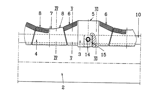
FIGURE l is an plan view of a walking or fixed beam
of a walking beam furnace;
FIGURE 2 is a side view of a walking or fixed beam
according to Fig. l;
FIGURE 3 is an plan view of a number support
members;
FIGURE 4 is a cross-sectional view about the line
IV-IV according to Fig. 2;
FIGURE 5 is a cross-sectional view along the line V-
V of Fig. 2, and
FIGURE 6 is a cross-sectional view along the line
VI-VI according to Fig. 2.
DETAILED DESCRIPTION OF THE PREFERRED EMBODIMENT
CA 02232208 1998-03-16
As shown in Figure 1, the walking beam and fixed
beam 1 comprise a cooled support pipe 2 having a
flat object support members 3 and round object
support members 4. The support members 3 and 4 are
arranged in alternating order on pipe 2.
As illustrated in Figure 2, the flat object support
members 3 have a flat support surface 5 as well as a
beveled surface 6 on both a forward and rear side
with respect to the direction of travel of the pipe
2. The round object support members 4 on the other
hand are distinguished by the narrow level surface 7
positioned in the middle (when seen from the side).
Beveled surfaces 8 rise up from the middle surface 7
on each side with respect to the direction of
travel.
The flat support surfaces 5 provide support surfaces
for flat objects, while the trough created by the
beveled surfaces 6, 8 and the level surface 7
receives round objects to be baked. In the flat
object support members 3, as best shown in Fig. 3, a
borehole 9 is provided for receiving a bolt 13 for
attaching member 3 to pipe 2. The bolt 13 is
prevented from falling out by means of a stopper 14.
The bolt 13 connects the flat object support member
3 with a locking cam 15 engaging a lengthwise
extending rib 10 as best shown in Fig. 6 The cam
15 is provided with a borehole in its middle for
receiving bolt 13.
The round object support members 4 are merely placed
on rib 10 of pipe 2 as shown in Fig. 4 and secured
in place by being sandwiched between two flat object
support members 3. As shown in Fig. 2, the
lengthwise ends of the members 4 are beveled
vertically inwardly so as to be locked by members 3.
CA 02232208 1998-03-16
As shown in Fig. 3, the flat receiving surface 5 of
the flat object support member 3 is broader or wide
(in a direction transverse to the direction of
travel) than its beveled portions 6 and the round
object support members 4. This provides the
necessary support surface for the flat object to be
baked.
The beveled surfaces 6 are further beveled laterally
to the right and left of the direction of travel.
The beveled surfaces 8 of the round object support
members 4 have such a beveling or downwardly sloping
surfaces 12 in a staggered manner as illustrated in
Fig. 4. This arrangement reduces the collection of
forging scales on the support members. Furthermore,
this arrangement of the support surfaces as well as
the alternation of the sideways beveled surfaces
have the effect of causing a continuously changing
support position on round objects in the furnace and
thereby improves the evenness of the heating.
In Figs. 4 through 6, it will be appreciated that
the base of the support members 3 and 4 have a U-
shape channel which mates with the shape of the riblO of pipe 2.
Although the invention as being described above with
reference to a preferred embodiment of the
invention, it is to be understood that other
constructions and embodiments are contemplated by
the present invention as defined in the appended
claims.