Note: Descriptions are shown in the official language in which they were submitted.
CA 02232293 1998-03-17
PCTIEP~l6/co I >o
Inflatable Gas Bag and Method for Manufacturing Same
The invention relates to an inflatable gas bag for an occupant
restraint system in a vehicle and a method for manufacturing
such a gas bag.
Occupant restraint systems with gas bags, frequently also
1u referred to as airbags, which are automatically inflated in the
case of a serious accident are nowadays installed in a
plurality of passenger cars both on the driver's side and on
the passenger's side in order to possibly avoid, in the case of
a serious frontal impact of the vehicle, potential head and
chest injuries of the vehicle occupants which are seated in the
front. Such systems which essentially consist of a mostly
pyrotechnical gas generator and a gas bag as well as of the
associated control electronics are increasingly employed in the
lateral area of passenger car: in order to dampen and
distribute the forces acting upon the vehicle in the case of a
side impact over a larger area and thus decrease the injury
hazard for the vehicle occupant who is seated on the impact
side. Such laterally arranged impact protection systems with
gas bag, which are also referred to as sidebags, are, for
example, accommodated in the vehicle doors or in the backrests.
On~the basis of the predominantly positive experience gained
with such impact protection systems which comprise a gas bag
the trend exists to employ such systems on a wider scale in
trucks and buses as well.
Depending on the task which an occupant restraint system of the
initially mentioned type is to fulfill, the gas bag in its
inflated state must have a pre=_cisely defined shape in order to
achieve the optimum effect. The so-called driver airbags in
their inflated state are, for example, approximately balloon-
shaped, while the so-called passenger airbags in their inflated
state are approximately cushion-shaped. Side airbags, in turn,
CA 02232293 1998-03-17
PCT,'EP')~~/o-t l W - 2 -
frequently still have intricate shapes in order to be able to
comply with the requirements ~.mposed on them.
In addition, gas bags must fu7lfi11 two contradictory
requirements: on the one hand they must be inflatable as
rapidly as possible when required; on the other hand they have
to provide as large a distance. as possible between the vehicle
occupant to be protected and t:he object with which the vehicle
occupant must not collide. While the first requirement calls
l0 for a small gas bag volume, a relatively large gas bag volume
is the result of the second requirement. The existence of
impact protection systems with a gas bag, however, is only
justified if their protective effect is as good as possible so
that nowadays large gas bag volumes are preferred in order to
achieve an optimum protective effect.
Conventional gas bags consist of two or more individual textile
parts which are cut from textile flat material and subsequently
sewn together. Accordingly, two circularly made-up two-
20~ dimensional textile parts are generally sewn together for a
driver's airbag. Upon inflating these conventionally
manufactured gas bags into thEair three-dimensional state which
they must assume in order to <achieve the desired protective
effect, creases occur in particular in the seam area, which
extend perpendicular to the seams. These creases result in high
stress peaks in the seam area which is already weakened by the
seam. In order to avoid bursting of the gas bag in the seam
area under load, very heavy f<~brics are used in the manufacture
of the gas bag. These heavy fabrics in conjunction with the
3o relatively large gas bag volume selected for achieving a good
protective effect result in conventional gas bags being
relatively heavy. In order to nevertheless ensure the rapid
inflation when necessary, larger gas generators have to be
employed which are capable of correspondingly rapidly
3.. accelerating the relatively large mass of the gas bag. Large
pyrotechnical gas generators in turn are disadvantageous in
that during inflation the temperature of the gas developed by
the gas generator reaches very high values and that these high
CA 02232293 1998-03-17
PCT/EP')~~I(l.l l W
temperatures can affect the gas bag and destroy its fabric. In
addition, a gas bag with a larger mass unfolds only later due
to its higher inertia so that the hot gases developed by the
gas generator act longer on the still folded fabric which is
located near the gas generator. In order to not destroy the gas
bag fabric as a result of thi~~ bombardment with the combustion
gases great yarn thicknesses (approx. 250 to 700 dtex) are
employed which ensure that the' fabric does not fail even then
when glowing particles impinge' on the fabric and individual
threads start melting.
The relatively large mass of conventional gas bags must, of
course, not only be accelerated but also stopped again at the
end of the inflation process. In this case, too, great loads
IS occur in particular in the seam area which must be compensated
by correspondingly reinforced seams or by multiple seams. These
measures again result in an increase in the gas bag weight.
The conventionally used heavy fabrics not only have dynamic
2o disadvantages but, in addition, enforce a relatively large
packing volume due to the fact. that they are also mostly
relatively rigid. The seam arenas are naturally particularly
rigid and can therefore cause undesired injuries such as, for
example, skin grazes of the occupant to be protected if the
25 occupant assumes a so-called out-of-position attitude while the
gas bag unfolds. Any attitude which does not correspond to the
optimum position relative to t:he gas bag is technically termed
"out-of-position", for example an occupant who is seated too
close to the gas bag or lateral to it. In such out-of-position
3o attitudes the risk to be fully hit by a rigid seam area is
particularly high.
In order to fulfill its protecaive function the gas bag must
comply with two additional and also contradictory requirements:
35 As already mentioned it must be inflatable as rapidly as
possible. This requirement can generally be met only with a
very tight gas bag because on:Ly then will it be ensured that
the gas developed by the gas generator is completely used for
CA 02232293 1998-03-17
PCT/EP'»~in.11 ~n - 4 -
inflating. On the other hand, the gas bag in the inflated state
must dampen the impact of an occupant of the vehicle. To this
end the gas bag must allow a defined venting of its gas filling
because otherwise the colliding occupant would bounce back.
Therefore, in the side facing away from the vehicle occupant,
conventional gas bags are provided with openings which can have
a diameter of up to 50 mm. These openings are also referred to
as "vents". Because these openings are not closed during
inflation, a considerable port=ion of the gas developed by the
to gas generator escapes so that the gas generator must have a
correspondingly more powerful,, i.e. larger, design in order to
be able to reliably inflate the gas bag. Large gas generators,
however, result in the above already explained thermal stresses
of the gas bag fabric.
Finally, the conventionally employed heavy fabrics are not
particularly tight because of the relatively great yarn
thick nesses used so that theae fabrics must generally be
additionally coated in order to obtain the required tightness.
The coatings, however, often have the problem of a poor ageing
stability so that the satisfactory function of the gas bag
might possibly no longer be ensured after many years.
Although known impact protection systems with gas bags
decisively improve the occupants' safety, thus justifying their
increasingly large-scale use, these systems still have quite a
number of drawbacks which prevent an even better protective
effect and moreover increase the manufacturing costs of
conventional systems.
3 Ci
The invention is based on the object to improve conventional
impact protection systems with gas bags in such a manner that
with an increased protective effect as many of the above
mentioned problems as possible are solved.
3 .~
According to the invention this object is solved by an
inflatable gas bag for an occupant restraint system, which
consists of a multilayered textile composite material which
CA 02232293 1998-03-17
4a
From DE-A-41 42 884 an airbag with an upper bag part and a
lower bag part is known which are joined together at their
margins. The upper bag part consists of an airtight web mate-
rial which is made from a fabric of two component composite
fibres. The one component of the composite fibres is a ther-
moplastic polymer whose melting point is lower than the melt-
ing point of the other fibre component. By means of heating
and, if required, pressing the flat fabric consisting of
these composite fibres the low-melting polymer material of
the composite fibres is molten, penetrates into the gaps of
the fabric, and seals them. According to an embodiment the
flat material can also be two-layered. Subsequently the
desired fabric parts are obtained by punching from the fabric
manufactured by means of hot pressing, which are then joined
together at their margins. Hot pressing and punching can also
be carried out in one operation.
w
CA 02232293 1998-03-17
PCTiEP~)~,iW l;n - 5 -
comprises at least one layer of a textile material and one
layer of a polymer material whose melting range is lower than
the melting range of the textile material, with the textile
composite material being formed into a predetermined three-
dimensional shape which is to develop during inflation of the
gas bag and the individual layers of the textile composite
material have been joined together only in the three-
dimensional shape of the gas bag.
The gas bag according to the invention therefore differs quite
essentially from the previously known gas bags: During its
manufacture it is already formed into the three-dimensional
shape which it is to assume in the inflated state. The
inventive gas bag is heat set in this three-dimensional shape
l5 by means of thermal treatment., Contrary to conventional gas
bags which are combined or sewn together, respectively, from
two-dimensional flat members, the described crease formation no
longer occurs during inflation of the inventive gas bag, which
in conventional gas bags causes dangerous stress peaks.
Due to the fact that the inventive gas bag is formed into its
three-dimensional functional state during manufacture, the
strength of its material can be selected considerably lower
compared to the previously employed materials because the
stress distribution in the ga:~ bag material of a gas bag
according to the invention is much more uniform. According to
the invention considerably more lightweight textiles can thus
be employed as gas bag material. In addition to the previously
described advantage of a more uniform stress distribution,
30~ forming the inventive gas bag into its three-dimensional
functional state during manufacture also makes it possible to
reduce the gas bag volume as compared to conventional gas bags
having the same protective effect because a gas bag according
to the invention can, for example, be preformed into an egg-
3_ shaped configuration and in this manner bridge the same
distance for which a ball-shaped gas bag with a correspondingly
larger volume is conventional:Ly required.
CA 02232293 1998-03-17
PCT'/EP')hi(>1 I ~(>
The inventive use of a multilayered textile composite material
results in further advantages: The now employable textile
materials of lighter weight need no longer be coated but rather
obtain their tightness by means of the layer of polymer
material which is but joined with the layers) of textile
material in the desired three-dimensional shape of the gas bag.
By means of suitable temperature control during the joining
process the resulting textile composite material can also be
given a defined gas permeability which can even be adjusted so
l0 as to be locally different. For example, on the side of the gas
bag facing away from the occupant areas with a higher gas
permeability can be generated so that the conventional vent
orifices can be dispensed with. Due to the omission of the
conventional vent orifices, the inflation losses of the gas bag
according to the invention are', on the one hand, much smaller
so that the use of a smaller c~as generator becomes possible
and, on the other hand, the weight of the gas bag is again
reduced because the conventional vent orifices are seamed by
one or several seams for stability reasons.
Furthermore the inflation dynamics of the gas bag according to
the invention can be influencE:d by a locally different
adjustment of the permeability of the textile composite
material, i.e. the shape can be precisely controlled during
inflation. Thereby, for example, the previously occurring and
undesired "mushrooming" (mushroom-type ejection of the gas bag
in the initial phase of the inflation process) can be
prevented. Restraining straps within the gas bag as were
previously employed to prevent. "mushrooming" can be dispensed
with in the inventive gas bag,. which again makes same more
lightweight. The precisely dei:inable permeability of the
textile composite material employed according to the invention
additionally permits a controlled venting of the inflated gas
bag and thus a nearly linear damping of the motion of the
colliding occupant. In other words, the inventive gas bag can
be imparted an accurately def_Lned deformation energy
absorption.
CA 02232293 2002-04-10
PCT/EP~JGIf)4150 - 7 -
In summary, the inventive gas bag even in its simplest
configuration offers the following advantages:
- While the previously used gas bag fabrics, e.g. for a gas
bag on the driver's side, have masses per unit area ranging
from approx. 180 glm2' to 22o g/m2 the multilayered
te~ctile composite material used according to the invention
in the molded state has a 30 to 50 per cent lower mass per
unit area.
' - While the previously used gas bag fabrics have tensile
strengths ranging from approx. 1,800 to 2,200 NJ5 cm (to
DIN 53875, Part 1) the multilayered textile composite
material of the inventive gas bag is required to have only
approx. 25 to 50 per cent of this tensile strength.
- While.the previously employed yarn thicknesses amount to
approx. 250 to 700 dtex the yarn thicknesses of the textile
material employed for the inventive gas bag may range from
2U approx. 20 to approx. 40 dtex.
- The gas bag according to the invention can be brought into
any shape which is desired from the point of view of safety
while at.the same time minimizing its volume.
- Due to its superior design the gas bag according to the
invention is generally considerably more lightweight than
previous gas bags and thus permits the use of smaller gas
generators.
The gas bag according to the invention requires a
v considerably lower packing volume which, for example,
allows the vehicle manufacturers to accommodate gas bags
with large volumes also in smaller visually more attractive
35' steering wheel hubs as are generally used in sports
steering wheels.
CA 02232293 1998-03-17
PCT/EP~)~~/n.11 sn ._ g _
According to a preferred configuration in terms of manufacture
and function the inventive gay: bag consists of several portions
each of which is formed into one part each of the three-
dimensional shape of the gas bag and which are joined together
s in the three-dimensional shaped of the gas bag, in particular by
lap sealing. According to this. configuration a gas bag intended
for the driver's side is prefE:rably formed by combining two
e.g. approximately hemispherical portions. Such a configuration
permits the use of a textile material for the side of the gas
1u bag facing the occupant which is different from that facing
away from the occupant so that: an optimum adaptation of the
textile material to different requirements can be effected. In
order to join the individual partial portions, all known
joining techniques (with or without an inserted auxiliary tape)
IS can generally be used. The individual portions can also be
glued or sewn together. The letter type of joining, however, is
the one considered the least advantageous.
The layer of a polymer material provided according to the
20 invention can be constituted by a plastic film or by a plastic
fleece. The layer of polymer material itself can consist of
several layers, for example, of two thin layers of a melting
adhesive between which a plastic film is arranged. The layers
of melting adhesive can, in turn, be formed by thin fleeces
25 (so-called hotmelt fleece). With a multilayered structure of
this type of the polymer material layer the joint area remains
soft and flexible also after hot sealing because the central
layer of the polymer material need not be heated to the flow
condition. Instead, only the thin melting adhesive layers are
3o heated to the flow condition and provide for the desired
intimate interconnection of the textile composite material.
According to a particularly preferred embodiment of the
inventive gas bag the textile composite material comprises at
35 least two layers of textile material between which the layer of
polymer material is arranged. This embodiment makes it possible
to select the textile material on the gas bag inner surface
different from the textile material on the gas bag outer
CA 02232293 1998-03-17
PCTIEP')~~IWI;o ._ g _
surface and, thus, to better adapt it to the different
requirements (inner surface temperature resistance, outer
surface softness, etc.). In addition, this embodiment also
makes it possible to make the properties of the inventive
s textile composite material more isotropic by joining together
the two layers of textile material with an opposite twist at a
defined angle in order to compensate, for example, the biaxial
elongation differences. It goes without saying that also three
or more layers of textile material can be used in order to
to achieve an even better isotropy. One layer of polymer material
is always arranged between two layers each of textile material.
In order to achieve a better isotropy the individual layers of
textile material need not conscist of different materials, but
may, of course, consist of the same textile material.
In the case of the inventive das bag, a knitted fabric, a warp-
knitted fabric, or a woven fabric can be used. Preferably,
however, knitted fabrics, i.e. warp-knitted or knitted fabrics,
are used because with knitted fabrics a very good isotropy can
be achieved in the three-dimensional functional state of the
gas bag, even in the case of only a few textile layers. Woven
fabrics, however, always have a warp and weft direction so that
a high isotropy is difficult t:o obtain.
In order to facilitate recycling of the gas bag according to
the invention, the layers of textile material and the polymer
material preferably consist of: the same material, for example,
of polyamide or of polyester.
The initially mentioned problems of conventional impact
protection systems with gas bags are also solved by an
inventive method for the manui=acture of an inflatable gas bag,
wherein a layered structure oi= at least one layer of textile
material and one layer of polymer material whose melting range
,5 is lower than the melting range of the textile material is
brought into the desired threes-dimensional shape which develops
on inflation of the gas bag or a portion of said shape by means
of heated forming tools and i:~ thermally set in this state and
CA 02232293 1998-03-17
PCT/EP~J~~/()-11 ~~> - 10 -
simultaneously laminated to a textile composite material. This
method is particularly well suited for the manufacture of a
previously described inventive. gas bag.
In the manufacturing method according to the invention the
layered structure whose layers> are not yet securely joined to
one another is brought into the desired three-dimensional shape
which may correspond to the complete gas bag or to a portion
therefrom between usually two heated forming tools and is
to thermally set in this state and simultaneously laminated to a
textile composite material. The method according to the
invention is thus a three-dimensional textile laminating and
molding method. In the inventive manufacturing method for gas
bags it must be ensured that no excessive compacting pressure
15 is generated between the forming tools so that the generating
textile composite material maintains its textile properties as
far as possible.
The thermal setting of the obtained three-dimensional shape is
2o effected by selecting the temperature of the forming tools such
that the textile material doer not begin to melt or is damaged
but is thermally set in the desired three-dimensional shape. If
required, thermal setting can be assisted by chemical auxiliary
agents and/or mechanical rubbing movements of the forming
25 tools. Due to the laminate generated in this manner the textile
composite material of the gas bag according to the invention
has an extremely high strength with a low weight. The mass per
unit area of the employed textile composite material in the
three-dimensional functional state preferably ranges from
approx. 100 g/mZ to approx. 1~i0 g/m2.
According to the invention, melting starts only with the layer
of polymer material in order 1=o achieve an intimate connection
with the textile layer or the textile layers. The commencement
35 of melting of the polymer layer can be controlled in such a
manner that, at the same time,, the permeability of the
generating textile composite material is accurately adjusted.
The temperature can thereby be controlled in a locally
CA 02232293 1998-03-17
PCTIEP'lhlO~ I iU -- 11 -
different manner so that locally different gas permeabilities
can be obtained. In addition t.o or as an alternative to the
possibility of adjusting the gas permeability of the gas bag by
means of controlling the temperature in the inventive
manufacturing method, it is also possible to perform a specific
mechanical perforation of the layered structure or the
generating textile composite material, e.g. by means of a
forming tool provided with needles, during the forming, heat
setting and laminating process:.
to
If the gas bag is to be combined from several portions, these
individual portions are joined together in the manufacturing
method according to the invention in the desired three-
dimensional shape, preferably by means of lap sealing. Compared
t5 to the previously used sewing technique which yields a maximum
of 50 to 60 per cent of the fabric strength in the seam areas,
at least almost the strength of the remaining textile composite
material is achieved also in t:he joint areas by means of lap
sealing. This leads to a significant weight saving for a gas
20 bag which is manufactured in accordance with the inventive
method. In addition, the edges of the individual portions of
the gas bag which are manufactured in accordance with the
inventive method can be exactl-y seamed with the seam not
extending outwardly or inwardl-y as hitherto but being flush
25 with the three-dimensional shape of the gas bag. Therefore, no
protruding seam is generated when joining the individual
portions but the joint area is also located within the
enveloping surface of the gas bag. In this manner a precise lap
sealing of individual portions becomes possible. In addition a
3o joint obtained by lap sealing is stronger and more lightweight
than a conventional sewn seam..
The inventive manufacturing mE~thod permits the individual
textile layers to be stretched during the forming process up to
,, an also locally defined residual elasticity. As already
explained in conjunction with the above described gas bag
according to the invention they inflation dynamics can~thereby
be precisely influenced. Moreover, stretching of the textile
CA 02232293 1998-03-17
PCT/EP~)i~/O.l I ~U -- 12 -
layers results in an increase of the tensile strength of the
textile composite material.
The inventive manufacturing meahod can be carried out with
textile materials made from a1.1 commercially available
synthetic fibres but also with textile materials from natural
fibres, e.g. mercerized cotton. It is of importance that the
melting range of the polymer l.ayer(s) is lower, preferably only
slightly lower, than the melting range of the textile material.
A number of successful test samples has already been
manufactured both from polyami.de and from polyester textile
materials. In general, such textile materials have a melting
range from approx. 21o to 240°C. The temperature to be selected
in the inventive manufacturing method when using such textile
1~ materials is therefore within a range of between approx. 180
and 210°C so that the textile material will not be damaged, the
polymer material layer, however just begins to melt.
The above described gas bags with their advantageous properties
can be manufactured by means of the inventive method. In spite
of the generation of a multilayered textile composite material
the manufacturing costs are, clue to the significantly lower
mass per unit area, considerably lower than the manufacturing
costs for conventional gas bags which must use the heavier
textile materials.
Although the just described manufacturing method has been
explained above with reference' to gas bags for impact
protection systems, it is obvious for those skilled in the art
that this manufacturing method can very advantageously be
employed for other formed parts made from textile materials as
well. For example, textile formed parts can be manufactured for
work, sports, leisure clothing or for containers of textile
materials such as rucksacks or bags. One sample application
would be to make clothing shoulder sections which are to be
rainproof but breathing by means of the inventive method. In
this manner the hitherto seam on the shoulder which leads to
tightness problems or which has to be sealed separately with a
CA 02232293 1998-03-17
PCTIEP~JC,/~).ll;n ~- 13 -
considerable amount of effort can be omitted. The method
according to the invention is therefore particularly suited for
the manufacture of formed textile parts which are to be
permeable for water vapour in one direction in order to be able
to emit the water vapour which is generated when sweating
during heavy physical labour amd waterproof in the other
direction in order to provide, for example, a protection
against rain.
to The invention will be explained in the following with reference
to schematic drawings of a preferred embodiment of an inventive
gas bag, in which:
Fig. 1 shows a conventional gas bag for an impact protection
15 system in a vehicle;
Fig. 2 shows a gas bag joined. from two portions, which is
manufactured according' to the invention;
20 Fig. 3 shows the joint area (detail 3) between the two
portions of the gas ba.g from Fig. 2 as a section and in
an enlarged illustration;
Fig. 4 shows the section thrc>ugh a textile composite material
25 used according to the present invention;
Fig. 5 shows the joining of t:wo gas bag halves manufactured
according to the invention;
30 Fig. 6 shows the manufacture of a gas bag half according to
the invention; and
Fig. 7 shows an example of a manufacturing tool for the
manufacture of a gas bag according to the invention
35 consisting of only onE: part.
Fig. 1 shows a conventionally manufactured gas bag 1 of an
impact protection system known from the state of the art which
CA 02232293 1998-03-17
PCT'EP')~~/O~l I W '- 14 -
is arranged on the driver's side in a motor vehicle, also
referred to as a driver airbag. The gas bag 1 consists of an
upper half 2 which faces towards the driver and a lower half 4
which faces away from the driver. The two halves 2, 4 are
joined together by means of a sewn seam 5 which in the
illustrated example is constructed as a double seam. The sewn
seam 5 forms a seam which projects essentially at right angle
from the gas bag 1 and which according to the detail drawings
la and 2a either projects into the interior of the gas bag 1 or
to outwardly from the gas bag 1. Both halves 2, 4 are made-up of
circular disk-shaped textile parts of flat textile material.
From Fig. 1 which shows the gas bag 1 in the inflated state it
can clearly be seen that the deformation which occurs during
15 the inflation process of the flat textile parts which
constitute the two halves 2 and 4 into the three-dimensional
state a plurality of creases 6 is generated in the joint area
of the two halves 2 and 4 as well as creases 7 which extend
from the connecting cone of the gas bag 1 over its lower half
20 4. The creases 6 extend essentially perpendicularly to the sewn
seam 5 and, like the creases '7, result in undesired stress
peaks in the gas bag fabric.
In the lower half 4 of the ga:~ bag 1 an orifice or opening 8
25 can also be seen through which the gas can be vented upon
impact of the vehicle occupant on the gas bag 1. If required,
several of such openings 8 arE_ provided. Due to the fact that
these openings 8 are not closed during inflation of the gas bag
1 a considerable amount of the filling gas which is actually
30 intended for inflation of the gas bag is already vented during
the inflation process.
The gas bag 1 shown in Fig. 1 is attached to a gas generator
(not shown herein) which is a~~commodated in the hub of a
ss steer ing wheel 9.
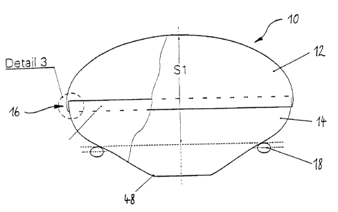
Fig. 2 shows a gas bag 10 according to the invention in the
inflated state. Contrary to the just described conventional gas
CA 02232293 1998-03-17
PCT/EP~m/W I ~U ~- 15 -
bag, two halves 12 and 14 of t:he inventive gas bag 10 shown in
Fig. 2 have been formed into t:he desired three-dimensional
shape and thermally set in this three-dimensional shape by
means of the method according to the invention. Contrary to the
state of the art the two halves 12 and 14 are not joined
together by means of a sewn seam but by a lap seal 16. A lap
seal of this type can, for example, be obtained by means of
ultrasonic sealing. The lap seal 16 has a very high strength
and causes only a minor material thickening in the joint area
so that the previously existing injury risk due to projecting
and/or rigid seams is minimized. The way of manufacturing gives
the inventive gas bag 10 a shape free of creases in the
inflated state. S1 identifies the functional distance which is
obtained in the inflated state between an area defined by the
steering wheel rim 18 and the maximum extension of the gas bag
10 in the direction towards the vehicle occupant.
Fig. 3 and Fig. 4 show in morn detail the structure of the
textile composite material of which the inventive gas bag 10
2U consists. The textile composite material of the illustrated
embodiment comprises three layers and consists of two layers
20, 22 of textile material between which one layer 24 of
polymer material is arranged which herein is formed as a
plastic film. In the joint area of the two halves 12 and 14 of
the gas bag 10 the layer 24 of: polymer material is brought into
a flowable condition, e.g. by means of ultrasound, so that the
polymer material penetrates the layers 20 and 22 of textile
material and is thus combined with the respective adjacent
textile material layer of the other half 12 or 14. After
;u cooling down of the polymer material which has been brought
into the flow condition in them overlap area of the two halves
12 and 14, the two halves 12, 14 are securely joined together
by means of the generated lap seal 16. Due to the fact that the
thickness of the layer 24 of polymer material is reduced during
,5 heat sealing the area of the :Lap seal between the halves 12 and
14 is only slightly thicker than the adjacent textile composite
material.
CA 02232293 1998-03-17
PCT/EPohiWl;n -- 16 -
Fig. 4 again shows a section through the structure of the
textile composite material. The layers 20 and 22 of textile
material may differ from each other, i.e. they may consist of
different textile materials.
The manufacturing of the gas bag 10 will now be described in
more detail with reference to Figs. 5 and 6. In the manufacture
of the gas bag 10 an apparatus: is used which may be a heated
female die tool 26 and an also heated male die tool 28 (see
to Fig. 5). Between the two forming tools 26 and 28 a layered
structure 30 is first placed which in the shown example
consists of two layers 20, 22 of warp-knitted textile material
and a layer 24 of polymer material in the form of a plastic
film which is arranged between them. Initially, the individual
15 layers of the layered structure 30 are not securely joined
together.
In a next step the two heated forming tools 26, 28 are moved
into contact with each other in order to bring the layered
20 structure 30 into that form which the gas bag 10 or a portion
of same is intended to assume later in the inflated state. Fig.
shows the closed condition of the two forming tools 26 and 28
with reference to an example for the manufacture of an upper
half of a driver's airbag. During the closing movement of the
25 forming tools 26 and 28 it may be useful to apply a vacuum to
the female die tool 26 in order to assist the sliding in of the
layered structure 30 into the forming tool 26. By maintaining
the layered structure 30 under- a defined counterstress during
the closing movement of the two forming tools 26 and 28, the
30 layers 20 and 22 of textile material which are arranged between
the two forming tools 26 and :?8 can be stretched up to a
predetermined residual elongat=ion property.
It is of importance that in the closed end position of the two
35 forming tools 26 and 28 no excessive compaction pressure is
exerted onto the layered structure 30 so that its textile
properties are maintained as far as possible. Therefofe, a
defined gap whose gap width depends on the structure of the
CA 02232293 1998-03-17
PCT/EP')~~/n-1 l ~n w 17 -
respective layered structure ?.0 is provided between the heating
layers 32 and 34 of the two forming tools 26 and 28.
In the position of the forming tools 26 and 28 as shown in Fig.
the layered structure 30 is simultaneously thermally set and
formed into a textile composite material in the three-
dimensional shape which is spE:cified by the forming tools 26
and 28. This is achieved in that the temperature of the forming
tools 26 and 28 is selected in such a manner that, on the one
lu hand, the two layers 20 and 22 are heated only to such an
extent that, in a similar manner to an ironing process, they
assume the shape as specified by the forming tools 26 and 28
free of creases, and that on t:he other hand, however, the
temperature is sufficient to just start melting the polymer
intermediate layer 24 at the t:wo layers 20 and 22 of textile
material. It has proven to be advantageous to select the
polymer material of the layer 24 in such a manner that its
melting range is only slightly, i.e. approx. 20 to 40°C, below
the melting range of the text~.le material.
After the described forming and heat setting process the
obtained formed textile part is brought exactly into the
desired dimension by means of a ring 36 which is arranged
concentrically with the male die tool 28 and a circumferential
?> groove 38 which is provided in the female die tool 26 by
engaging a blade (not shown) :into the circumferential groove 38
for cutting off any surplus margin. Alternatively, this exact
dressing can also be carried out e.g. by means of a resistance
wire embedded in the male die tool 28, which is briefly heated
and thereby melts off the surplus margin. After the dressing
operation the two forming too:Ls 26 and 28 are opened again and
the formed textile part, in the shown example one half of a gas
bag, can be removed. The textile formed part is as soft and
supple as a textile piece and can therefore be folded
,5 extraordinarily well.
Fig. 6 shows how two separately manufactured gas bag halves are
joined. For this purpose a lower gas bag half 40 is first
CA 02232293 1998-03-17
PCT/EP'Jhi().11 ;o - 18 -
placed into a female die tool 26' and then an upper gas bag
half 42 turned to the inside is placed upon the lower gas bag
half 40. An annular loose part. 44 made of steel or PTFE is
arranged in the joint area between the upper gas bag half 42
and the lower gas bag half 40 so that the margins of the upper
gas bag half 42 and the lower gas bag half 40 overlap on the
radially outer circumferentia7. surface of this loose part 44.
This is schematically indicated in Fig. 6 by a small gap
between the overlapping margins.
to
Subsequently the two overlapping margins of the upper and lower
gas bag half are heat sealed t:o one another, for example by
means of an ultrasonic sonotrode 46 and the loose part 44 as a
counter support. The two gas bag halves 40 and 42 are then
joined to form the gas bag 10 and after opening of the forming
tools 26', 28' only the loose part 44 has to be removed through
the gas generator connecting port of the formed gas bag 10.
With the described manufacturing method gas bag halves 40 and
42 with an accurately defined gas permeability can be
manufactured in that the tempearature of both forming tools 26
and 28 is accurately, also locally, controlled. Alternatively
or additionally, the female die tool 26 can be provided with
needles which later perforate the generated textile composite
material (not shown). It is therefore possible to manufacture
gas bags 10 with a gas bag shape which is individually matched
to a certain vehicle type and locally different gas
permeabilities by means of they described manufacturing method
so that the impact energy of a vehicle occupant can be
optimally absorbed and dampened. In addition, the filter effect
of the gas bag 10 can be adju:~ted without special nozzles in
such a manner that both an opt=imum dynamic behaviour during the
inflation process is achieved and the ingress of harmful gases
into the area of the occupants is prevented to a large degree.
Finally, Fig. 7 shows a possibility of manufacturing a gas bag
10 in one part and without heat sealing joint. For this purpose
the layered object is drawn or blown, respectively, into a
CA 02232293 2002-04-10
- 19 -
hollow mould 48 and hot air is then blown through the gas
generator connecting port 50 into the gas bag l0 so that
the individual layers of the layered structure fit snugly
to the hollow surface of the hollow mould 48 and are
thermally set there and laminated to the composite
material, Cooling air is then blown in through the gas
generator connecting port 50 and the completed gas bag 10
is removed.