Note: Descriptions are shown in the official language in which they were submitted.
CA 02232352 1998-04-20
WO 97II4362 PCT/US96/I6766
1
APPARATUS AND METHOD FOR DISRUPTING VEIN VALVES
BACKGROUND OF THE INVENTION
Field of the Invention
This invention relates generally to the apparatus and method
for disrupting vein valves in a mammal.
Discussion of the Prior Art _ _,_ ... _.
It is well known that the vascular system is relied on to
nourish the cells of the body and to remove waste materials from the
cells of the body. More specifically, the arteries of the vascular
system convey oxygen and other nutrients to the cells, while the veins
of the vascular system return the blood and waste materials from the
cells to the lungs, liver, heart and other organs of the body.
Since the flow of blood from the extremities is generally
upward, this return flow of blood in the veins must work against the
force of gravity. To assist with the return flow, veins commonly
include several valves which permit a flow of blood in the upward
direction while inhibiting a flow of blood in the downward direction.
Thus, the vein valves in their normal state aid in moving the blood in
an upward direction against the force of gravity from the extremity to
the organs of the body.
CA 02232352 1998-04-20
WO 97/14362 PCT/US96/16766
2
The circulation of blood to and from the cells if of particular
concern in the extremities of the body, such as the hands and feet,
where the cells are located the greatest distance from the organs.
When blood is not appropriately circulated, the unnourished cells die
sometimes resulting in loss of the associated hand or foot.
In order to avoid amputation, it has long been known that
circulation to these extremities may need to be enhanced particularly
in old age. When for example, the femoral artery becomes blocked, it
is advantageous to bypass this blockage in order to enhance the flow
of blood to the lower leg and foot. In a common procedure, the
saphenous vein is used for this purpose. Particularly when the
blockage occurs in the upper region of the femoral artery, the
saphenous vein can be harvested and reversed before attachment to
the femoral artery above and below the blockage. This reversal of the
vein orients the valves in a direction which facilitates a flow of blood
toward rather than away from the extremities.
Particularly for these lower regions, an insitu procedure has
evolved where the saphenous vein is left in place but its valves are
disrupted in order to enhance a flow of blood in the reverse direction,
toward rather than away from the extremity. In this procedure, the
proximal end of the vein is attached to the proximal end of the
femoral artery, while the distal end of the vein is attached to the
distal end of the femoral artery.
It is the description of these valves in the in situ procedure
which is of particular interest to the present invention. When the
valves are disrupted, the flow of blood in a reversed direction through
the vein is enhanced to promote circulation to the extremity.
A vein will typically have several valves along its length each
consisting of two and perhaps three cusps sometimes referred to as
leaflets. These leaflets form flexible cups which open upwardly. A
CA 02232352 1998-04-20
WO 97/14362 PCT/LTS96/I6766
3
flow of blood in the upward direction moves the leaflets outwardly
permitting the passage of blood. However, the force of blood, typically
~ aided by gravity, in the downward direction fills the cups so that they
form seals with each other to inhibit downward flow. The leaflets are
typically symmetrical about the axis of the vein. Thus, in a bileaflet
valve, the cusps are usually separated by 180°. In a trileaflet valve,
the cusps are separated by 120°.
Rendering the valve incompetent should be accomplished with
a minimum of operative manipulation. This is important realizing
that the inner surface of the vein is lined with endothelial cells which
cannot regenerate themselves. Any damage to this endothelial lining
can be particularly traumatic to the patient. It has been found that
the easiest and least traumatic procedure involves cutting the leaflets
radially of the vein axis while they are in their naturally closed
position. This cutting of the vein valves is typically accomplished
with an instrument referred to as a valvulotome. In the past, these
instruments have been provided with a proximally facing cutting
surface which has been manipulated to engage each of the leaflets in
order to tear the leaflet and render the valve incompetent.
One common valvulotome has the configuration of a hockey
stick. Such an instrument must be manipulated into position for
each of the leaflets in each of the valves. Accordingly, there is
considerable requirement for operative manipulation typically leading
to a substantial endothelial damage. Such valvulotome designs also
suffer in their tendency to engage side branches of the vein. Where
cutting occurs at the junction with side branches, considerable
damage can be done to the vein greatly increasing the complexity of
the operation and the trauma to the patient. As a consequence, the
use of scissors and other valvulotomes of the type discussed has
typically been accomplished only under visualization. With this
' ~ CA 02232352 1998-04-20
. _ .. . ~.
~ ' 4
visualization, typically provided by an endoscope, the
operator can visualize the process and hopefully avoid damage
to the vascular system. Unfortunately, the presence of the
endoscope within the vein further enhances the possibility of
trauma to the endothelial lining of the vessel. In addition,
direct visualization can be time consuming and can add to the
blockage which tends to deprive the vein of its blood supply.
This even further increases the risk of endothelial damage.
As a result of the aforementioned factors, many of the
valvulotomes have been designed to pull the valve leaflet
against an anvil or backing so that the cutting element is not
exposed to side branches during travel within the vessel.
Unfortunately, these devices have been limited in the size of
their cut so that generally only a "nip" is made in the cusp.
Where this is inadequate, additional passes and cutting of the
leaflet is required.
The foregoing deficiencies noted with respect to the
prior valvulotomes and procedures are overcome with the
present invention which provides for full radial cutting of
each leaflet of eachTvalve in a single, blind pass through the
vessel. The valvulotome of the present invention-includes a
cutting element which can be introduced into the vessel
without direct visualization. As a consequence, an endoscope
is not required so that the duration of the procedure can be
reduced without additional blockage in the vein. Multiple
cutting sections are oriented along a plate which is formed
with a helical configuration. With this structural
orientation, each of the leaflets in this valve will be
engaged by at least one of the cutting sections without any
axial rotation of the valvulotome. This significantly reduces
the operative
CA 02232352 1998-04-20
, _ , . i,
y
manipulation necessary for the procedure. By providing
multiple cutting sections in the valvulotome, each with its
own cutter radially displaced from the cutters in the~other
sections, each of the leaflets will be cut with a single axial
5 movement of the valvulotome through the vein. The sharp
cutting surfaces in each of the cutting sections are oriented
to face a shoulder in the cutting section. This shoulder
extends outwardly a distance sufficient to inhibit the
structure from engaging any irregularities, such as side
branches.
In one aspect of the invention, the valvulotome is
adapted for disrupting the cusps of the valve in a vein of a
patient. The instrument includes a shaft having an elongate
configuration which is sized and configured for insertion into
the vein along the axis of the vein. A cutting member having
an axis extending between a proximal end and a distal end is
twisted about the axis. The proximal end of the cutting
member is attached to the shaft. First portions of the
cutting member define a first cutting edge extending generally
outwardly of the axis of the cutting member. Second portions
of the cutting member define a second cutting edge which is
similar to the first cutting edge. The first portions are
angularly displaced from the second portions so that at least
one of the first and second portions engage the ousp of the
valve regardless of the radial orientation of the valve within
the vein.
An additional aspect of the invention includes a
valvulotome for disrupting valve cusps in the vein of a
patient. A shaft having an elongate configuration is sized
and configured for insertion into the vein. A cutting member
has an axis extending between a proximal end and a distal end
which defines an axial direction extending along the axis and
an angular direction extending around the axis. First and
second portions of the cutting member define respective first
and second cutting edges each of which extends generally
outwardly of the
CA 02232352 1998-04-20
WO 97/14362 PCT/CTS96/16766
6
axis and faces generally proximally of the cutting member. Third
portions of the cutting member define a shoulder disposed in close
proximity to the first portions of the cutting member. These third
portions define with the first portions of the cutting member a slot
which extends proximally with progressive outward positions along
the cutting member.
A further aspect of the invention comprises steps of a method
for disrupting first and second cusps of a valve in the vein of a
patient. The steps include the provision of a valvulotome with a shaft
and a cutting member, the shaft having an axis extending between a
proximal end and a distal end and the cutting member having a first
cutting edge and a second cutting edge. The valvulotome is inserted
distally into the vein and beyond the cusps of the valve. When the
shaft of the valve is withdrawn proximally. The cutting member is
moved through the vein causing the first cutting edge to engage and
disrupt the first cusp of the valve and the second cutting edge to
engage and disrupt the second cusp of the valve. During the
withdrawal step, rotation of the valvulotome is inhibited in order to
protect the vein.
In yet a further aspect of the invention, a medical device is
adapted for use in a body conduit and includes an operative member
having a first axis and a shaft having a second axis, a coupling
disposed between the shaft and operative member has swivel
characteristics permitting angular movement of the first axis relative
to the second axis. A sleeve disposed circumferentially of the
coupling between the shaft and operative member has elastomeric
characteristics forming a bias which urges the operative member and
shaft into an aligned relationship and which permits the angular
movement between the operative member and shaft against the bias
of the sleeve.
CA 02232352 1998-04-20
WO 97/14362 PCT/US96/16766
7
These and other features and advantages of the invention will
become more apparent with a discussion of preferred embodiments
and best mode of the invention, and reference to the associated
drawings.
' S
DESCRIPTION OF THE DRAWINGS
Fig. I is a front perspective view of a human leg including an
artery with a blockage and a saphenous vein with vein valves;
Fig. 2 is a perspective view of the Ieg with a saphenous vein
retained in situ and the valves disrupted to bypass the blockage in
the artery;
Fig. 3 is a side view of the saphenous vein illustrating side
branches of the vein in a preferred embodiment of the valvulotome of
the present invention;
Fig. 4 is a cross section view of the vein taken along lines 5-5 of
Fig. 3;
Fig. 5 is an enlarged view of the vein with the valvulotome
being retracted to disrupt a valve in the vein;
Fig. 6 is an enlarged view of a helical blade configuration
associated with a preferred embodiment of the valvulotome;
Fig. 7 is an enlarged perspective view of a cutting section
associated with one embodiment of the present invention;
Fig. 8 is a perspective view of a further embodiment of the
invention wherein the valvulotome has a cylindrical configuration.
Fig. 9 is a side elevation view of a further embodiment of the
valvulotome wherein the cutting member is formed from a wire;
' Fig. 10 is an end view of the wire cutting member illustrated in
Fig. 9;
CA 02232352 1998-04-20
WO 97/14362 PCT/US96/16766
8
Fig. 11 is a side elevation view of a flexible coupling permitting
angular movement and displacement of a cutting head and shaft
associated with the present invention; and .
Fig. 12 is a side elevation view partially in section taken along
the lines 12-I2 of Fig. lI and illustrating an aligned configuration of
the cutting head and shaft.
DESCRIPTION OF PREFERRED EMBODIMENTS
AND BEST MODE OF THE INVENTION
A valvulotome is illustrated in Figure I and designated
generally by the reference numeral 10. The valvulotome 10 includes
a cutting head 12 and a control member or shaft 14. In a preferred
embodiment, the shaft 14 is formed from stainless steel or a shaped
memory alloy; the cutting head 12 is preferably formed from stainless
steel.
In Figure 1 the valvulotome 10 is illustrated to be operatively
disposed in a saphenous vein 16 of a leg I8. the vein 16 has a central
axis 17 and a vessel wall 19 which are best illustrated in the enlarged
view of Figure 3. As described in greater detail below, it is the
purpose of the valvulotome 10 to prepare the saphenous vein 16 for
use as a bypass graft in order to increase the flow of blood to an
extremity of the human body. Although the leg I8 is illustrated in
Figure 1, it will be apparent that the valvulotome 10 can be equally
effective in preparing other veins such as those occurring in the arms
(not shown) to improve circulation for example to the hand.
The leg 18 extends downward from a groin 21 and includes an '
upper leg or thigh 23, a knee 24, and a lower leg 25 which is
connected to a foot 27. The skeletal structure in this region includes
CA 02232352 1998-04-20
WO 97/14362 PCT/CTS96/i6766
9
a pelvis 30, a femur 32, in the thigh 23, and a tibia 34 and fibula 36
in the lower leg 25.
In the extremities, the circulation system is of greatest interest
to the present invention. This system includes arteries which carry
blood from the heart (not shown) to the distal regions of the body. In
the leg 18, the primary artery is the femoral artery 41 which extends
from the area of the groin 21 past the knee 24 into tributaries
including the peritoneal artery 43 and the posterior tibial artery 45.
It follows that in the femoral artery 41, downstream is toward the
extremity, such as the foot 27, and upstream is toward the groin 21.
It is the blood flowing in the femoral artery 41 which carries oxygen
and other nutrients to the foot 27.
The circulatory system also includes the venous system which
carries blood with carbon dioxide and various waste products from the
cells at the extremities back to the organs, such as the heart (not
shown). In the abdomen, the kidneys remove the waste products
from the blood, the lungs oxygenate the blood, and the heart pumps
the nutrified blood back into the femoral artery 41.
In the femoral artery 41, blood flows in the direction of an
arrow 47 from an upstream end 50 of the groin 21 to a downstream
end 52 in the lower Ieg 25. In the vein 16, the flow is reversed. This
flow is in the direction of an arrow 54 from an upstream end 56 to a
downstream end 58.
When a person is standing, blood flow in the femoral artery 41
is enhanced by gravitation. However, blood flow in the vein 16 is
resisted by gravity. For this reason, the vein I6 commonly includes
several valves 61 which facilitate flow toward the downstream end 58
' but which inhibit flow toward the upstream end 56. With these
valves 61, the flow of blood in the saphenous vein 16 is encouraged
against the gravitational force.
r.
CA 02232352 1998-04-20
s. ~ 10
The problem being solved by the present invention occurs
when the flow of blood to the extremities, such as the hand or
foot 27, is insufficient to nourish the cell in those.distal
regions. This reduced blood flow may result from blockage
such as an embolus 63, or arterial sclerosis, a thickening of
the vessel walls. In order to improve this blood flow, it is
desirable to bypass any restricted portion of the femoral
artery with a graft which can carry the nutritive blood
parallel with the damaged artery 41. The saphenous vein 16
has been used for this purpose. Turning this vein into an
arterial graft removes it from the venous system but other
veins can pick up the additional demand for return blood flow.
Preparation of the vein 16 to function as an arterial
graph is typically accomplished in an in situ procedure
wherein the saphenous vein is retained in its normal
orientation in the leg. With this orientation, the valves 61
inhibit the downward flow of blood. Therefore, in accordance
with the procedure, the valves 61 are disrupted so that the
downward flow, in the direction toward the feet, can be
accommodated.
The valvulotome 10 and procedure of the present invention
are best illustrated in the enlarged view of Figure 3 where
three of the valves 61 are designated by the reference
numerals 61a, 61b and 61c. The vein 16 is further
characterized by sidebranches 65 and 67 which communicate with
the vein 16 at junctions designated generally by the reference
numerals 70 and 72, respectively.
As illustrated in Figure 3, the valvulotome 10 is being
inserted through the vein 16. It is passed through the
valve 61c and is in the process of passing through 61b. It
has not yet reached valve 61a which is shown in its natural
state.
This valve 61a in its natural state is best illustrated
in the cross sectional view of Figure 4. This figure also
presents the best
' CA 02232352 1998-04-20
T 11
view of an endothelial lining 74 which is disposed along the
interior surface of the vein 16. This lining 74 is not
capable of regenerating itself. As a consequence damage to
the lining 74 significantly increases the trauma to the
patient.
Also in Figure 4, the valve 61a is illustrated to have a
bileaflet configuration. In other words, it includes two
leaflets 76 and 78 which are generally symmetrical but
displaced 180E from each other. The leaflet 76 extends from
the endothelial lining 74 and extends inwardly across about
one-half of the lumen of the vein 16. The leaflet 78
similarly extends from the endothelial lining 74 inwardly
toward the leaflet 76. In their natural state, the
leaflets 76 and 78 form a seal against each other generally at
the axis 17. The purpose of the valvulotome 10 is to cut the
leaflets 76 and 78, for example along the dotted lines 81 and
83, respectively. For maximal disruption of the valve 61c,
these cuts preferably extend along the entire radius of the
leaflets 76, 78 into general proximity with the endothelial
lining 74.
The valvulotome 10 is of particular interest to the
present invention and includes the shaft 14 and the cutting
head 12 as previously discussed. The shaft 14 can be
generally any elongate member, having both tension and
compression characteristics, which is sufficiently flexible to
negotiate the saphenous vein 16. The shaft 14 must have
compression characteristics sufficient to push the cutting
member 12 through the vein 61. It must also have tension
characteristics sufficient to withdraw the cutting member 12
proximally through the vein 61. In a preferred embodiment,
the shaft 14 is elongate and cylindrical in configuration. It
is formed from either stainless steel or a nickel titanium
alloy, and has a diameter of about .024-.028 inches. The
shaft 14 is coupled to the cutting member 12 at a junction 90.
CA 02232352 1998-04-20
WO 97/14362 PCT/US96/16766
12
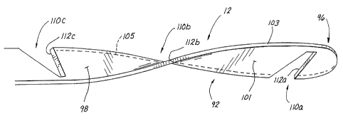
It will be noted that the cutting head 12 in the embodiment of
Figure 5 has the configuration of a blade 92 which extends along the
axis 17 between a proximal end 94 and a distal end 96. The blade 92
is defined by a pair of generally parallel major surfaces 98 and 101
which are bounded by lateral surfaces 103 and 105 that meet at the
distal end 96 as best illustrated in Figure 6. The blade 92 in this
embodiment is twisted into the general configuration of a helix.
Multiple cutting sections 110 are formed along the axis 17 of
the blade 92. In the illustrated embodiment, there are three cutting
sections designated by the reference numerals 110a, 110b and 110c.
These cutting sections 110a-c are similar in size, shape and function
in this embodiment. The cutting sections 110a-c are axially spaced
relative to each other and, due to the helical configuration of the
blade 92, also angularly spaced relative to each other.
Of particular interest to the present invention are a plurality of
cutting edges 112a-c each of which is associated with one of the
cutting sections 110a-c. For example, the cutting edge 112c is formed
by first portions of the blade 92 in the cutting section 110c.
Similarly, second portions of the blade 92 form the cutting edge 112b
in the cutting section 110b. The cutting edge 112a is formed in the
cutting section ll0a. It will be noted that in the embodiment of
Figure 6, each of the cutting edges 112a-c faces proximally of the
blade 92, and is axially spaced relative to the other cutting edges
112a-c.
Importantly, the cutting edges 112a-c are also angularly spaced
relative to each other. In this embodiment, this angular spacing
occurs automatically due to the helical configuration of the blade 92.
It is this angularly spaced relationship of the cutting edges 112a-c
which enables the valvulotome 10 to engage each of the leaflets 76, 78
of the valve 61 without rotation of the shaft 14 or the blade 92 within
CA 02232352 1998-04-20
WO 97/14362 PCT/US96/I6766
13
the vein 16. As a result, all of the leaflets 76, 78 of the valve 61 can
be disrupted with a single, non-rotational pass of the valvulotome 10
through the vein 16. This greatly reduces trauma to the patient and
offers a high degree of protection for the endothelial layer 74.
' 5 Other structural elements associated with the cutting section
110c are discussed with reference to Figure 7. In this enlarged view
it can be seen that the first portions of the blade 92 associated with
the cutting edge 112c also define a proximal facing surface 114c
which is beveled or otherwise sharpened to form the edge 112c. In
the preferred embodiment, the surface 114c is beveled at an angle a,
such as 30° relative to the major surfaces 98, 101. With respect to
the central axis 17, the surface 114c may have an angle A. In the
preferred embodiment, this angle 8 is an obtuse angle such as 120°.
This relationship orients the surface 114c at an acute angle (3 relative
I5 to the lateral surface 105. In this embodiment, the angle 8 is about
48-50° and is measured at a Iine of intersection 116c. It will be noted
that these angular relationships of the surface 114c relative to the
axis 117 and the surfaces 98, 101 and 105, form a point 118c along
the cutting edge 112c and the surface 105. Although this point 118 is
disposed along the outer edge of the blade 92, it may be blunted in
order to inhibit any engagement of the sidebranches 65.
Third portions of the blade 92 define a surface 121c which faces
outwardly and distally toward the surface 114c. The surface 121c is
generally planar but is angled proximally with progressive positions
outwardly of the axis 17. At the lateral surface 105, the surface 121c
forms a shoulder 123 which has a preferred orientation relative to the
point 118. This orientation is based on both the axial and the radial
separation of the shoulder I23 and the point 118. Preferably, the
shoulder 123 extends radially from the axis 17 a distance at least as
great as the radial displacement of the point 118 from the axis 17. It
CA 02232352 1998-04-20
.
.
.,r.. _.
' 14
is also preferable that the shoulder 123 be positioned in
sufficient axial proximity to the point 118 that movement of
the surface 105 and the shoulder 123 through a vessel. will
inhibit any cutting contact between the point 118 and the
sidebranch 65 (Figure 3). This axial spacing is preferably
within a range of about .150-.175 inches. In a preferred
embodiment, the axial spacing of the shoulder 123 relative to
the point 118 is about .165 inches.
In order to maintain this preferred orientation between
the shoulder 123 and the point 118, the surface 121c can be
gradually curved into the surface 114c to form a transition
surface 125c at the base of the cutting section 110c. The
transition surface 125c in a preferred embodiment is disposed
on a side of the axis 17 which is opposite the shoulder 123
and the point 118. In other words, the slot formed by the
surfaces 114c, 121c and 125c extends across the axis 17. This
slot, which is designated by the reference numeral 126 in
Figure 7, extends generally in the direction of its defining
surfaces 114c and 121c, that is proximally with progressive
outward positions from the axis 17.
As noted above, the shoulder 123 functions to ensure that
the point 118 does not engage a sidebranch, such as the
sidebranch 65. This same function is served by a different
shoulder 124 which is disposed distally of the point 118.
This shoulder 124.is defined generally by the major
surfaces 98, 101, the lateral surface 105, and the
surface 114c. In effect, both the shoulders 123 and 124
function to ensure that cutting occurs only within the
cylindrical space defined by the vessel walls. The
sidebranches 65 which extend outwardly of that imaginary
cylinder cannot be engaged by the point 118 as long as the
shoulders 123, 124, and more specifically the lateral
surface 105, extend radially at least as far as the point 118.
CA 02232352 1998-04-20
' 15
Each of the shoulders 123, 124 preferably extends axially
a distance greater than the diameter of the ostium of a
sidebranch. In a normal anatomy, this requirement is.-
generally met if the length of the shoulder 124 along the
axis 17 is at least twice as great as the width of the cutting
head 12.
There are several advantages associated with the cutting
section 110c. With the shoulder 123 extending radially as far
as the point 118, it serves as a protective structure which
keeps the point 118 from entering any of the sidebranches 65.
The shoulder 123 occurs along the surface 105 and does not
represent a protrusion or any other area of increased pressure
which might damage the endothelial lining 74. While
inhibiting any possibility that the cutting section 110c would
catch on one of the sidebranches 65, it is nevertheless sized
and configured to receive the cusps of a valve such as the
valve 61b illustrated in Figure 3. The depth of the cutting
section 110c is relatively deep and preferably extends more
than half the distance across the blade 72. This ensures that
cutting occurs substantially along the entire radial dimension
of the leaflet 76, 78 of the valve 61.
In a preferred embodiment of the invention, the detail
disclosed above with reference to the cutting section 110c in
Figure 7 is duplicated in both the cutting section 110a and
2 5 110b .
An additional embodiment of the invention is illustrated
in the perspective view of Figure 8. In this embodiment,
elements of structure which are similar to those previously
disclosed will be designated by the same reference numeral
followed by a single prime ('). Thus it can be seen that the
embodiment of Figure 8 includes a cutting head 12' which is
molded or otherwise attached to a shaft 14'. Both the cutting
head 12' and shaft 14' are disposed along a common
CA 02232352 1998-04-20
WO 97/14362 PCT/US96/16766
16
axis 17'. This embodiment also includes multiple cutting sections
designated by the reference numerals 110a'-c'.
The embodiment of Figure 8 is similar to that previously -
discussed in that the cutting sections 110a'-c' are angularly displaced
as well as axially displaced relative to each other. It differs from the
embodiment of Figures 3-7 in the shape of the cutting sections lloa'-
c' and also in the configuration of the cutting head 12'. In this case,
the cutting head 12' has a cylindrical configuration and can be formed
as either a solid cylinder or preferably as a hollow cylinder or tube
such as that illustrated in Figure 8. In either case, the cylinder of
the cutting head 12' will have an outer surface I27. In the tubular
embodiment, the cylinder of the cutting head 12' will also have an
inner surface 130 which defines the cutting edges 112a' and 113, of
the cutting head 12'.
Similar to the manner previously described, the cutting section
110a' can include a surface 114a' which is beveled or otherwise
sharpened to form a cutting edge 112a'. In this case however the
cutting section ll0a' also includes .a second cutting edge 113a which
is formed by a second surface ll5a. The configuration of this
opposing surface 115a can be better understood with reference to a
similar surface 115c which is shown in full view in the cutting section
110c'.
A point 118' is formed at the intersection of the two surfaces
114a' and 115a, with the outer surface 127 of the cutting head 12'.
This point 118' can be dulled, blunted or rounded as previously
discussed.
Opposing the cutting edges 112a' and 113a is the surface 121a'
which is oriented to face the surfaces 114a' and 113a. The surface
121a' can be continuous and planar to facilitate manufacture. A
shoulder 123a' is formed at the intersection of the surface 121a' and
CA 02232352 1998-04-20
WO 97/I4362 PCTliJS96/t 6766
17
the outer surface 127 of the cutting head 12'. This shoulder 123a' is
not as prominent as that previously described but nevertheless
- functions to inhibit any snagging of the sidebranches 65 by the point
118'.
" 5 If the cylindrical cutting head 12' is provided in a tubular
configuration, then the cutting section 110a' will have two transition
surfaces 125a' and 126a. These surfaces 125a' and 126a are formed
in a single plane in a preferred embodiment.
This particular embodiment offers several advantages including
a relatively large outer surface 127 which tends to develop a reduced
pressure and hence greater protection for the endothelial lining 74 of
the vein 16. The provision of multiple cutting edges 112' and 113 in
each of the cutting sections 110a'-c' also provides for greater
disruption of the leaflets 76, 78 associated with the valve 61. It may
also be easier to grind the cutting sections 110a'-c' when the cutting
head 12 is provided i.n the form of a cylinder rather than a helix.
Figure 8 illustrates another feature of the invention which may
be applicable to each of the embodiments of the valvulotome 10. This
feature includes a hollow sheath 13I with a distal portion 133 having
an inside diameter greater than the diameter of the cutting head I2.
A proximal portion 135 of the sheath 131 extends circumferentially of
the shaft 14 to the proximal end of the valvulotome 10. Operation of
the proximal portion 135 at the proximal end of the valvulotome 10
moves the distal portion 133 of the sheath I31 between two positions.
In the ~.rst position, the distal portions 133 of the sheath 131 are
disposed circumferentially of the cutting head 12 to cover the cutting
edges _112 and thereby prevent cutting. In a second position, the
distal portions 133 are disposed circumferentially of the shaft 14 to
expose the cutting edges lI2 and thereby permit cutting.
CA 02232352 1998-04-20
WO 97/14362 PCT/US96/16766
is
A further embodiment of the invention is illustrated in the side
view of Figure 9 and the end view of Figure 10. In this embodiment,
elements of structure which are similar to those previously disclosed .
will be designated by the same reference numeral followed by a
double prime ("). Thus it can be seen that the invention as embodied "
in Figure 9 utilizes a cutting head 12" having three cutting edges
112a"-c".
The cutting head 12' includes a first leg 132 which may
comprise an extension of the shaft 14". The leg 132 extends generally
parallel to the axis 17" and is connected to a second axial leg 134
through a transverse leg 136. Similarly, the second leg 134 is
connected to an axial Ieg 138 through a transverse leg I41. Beyond
the third leg 138, the wire forming the cutting head 12' is bent back
on itself through an end section 143 to form a return leg 145 which
terminates in a third transverse leg 147. It is the transverse legs
136, 141 and 147 which are of particular interest to the present
invention since these legs are ground, sharpened or otherwise shaped
to form the cutting edges 112c", ll2b", and 112a", respectively. With
reference to Figure 9, it can be seen that these cutting edges 112a"-c"
are spaced from each other along the axis 17". From the end view of
Figure 10, it can be seen that the transverse legs 14'1, 141, and 136
are also spaced from each other angularly, in this case by an angle of
120°.
Another feature of the present invention is best illustrated in
Figures 11 and 12. In these figures, the shaft 14 and the cutting
member or head 12 can comprise any of the embodiments previously
described. Thus the shaft 14 can be formed from a wire having the
axis 17 extending between a proximal end 152 and distal end 154.
Cutting head 12 can have an axis 156 extending between the
proximal end 94 and distal end 96.
CA 02232352 1998-04-20
WO 97/14362 PCT/US96/I6766
19
Of particular interest to this embodiment is a flexible coupling
designated by the reference numeral 158. This coupling 158
preferably has characteristics which permit angular movement
between the axis 17 of the shaft 14, and the axis I56 of the cutting
' 5 head 12. This angular movement may be desirable as the
valvulotome 10 is being drawn through the vein 16 (Figure 1). Body
conduits of this type sometimes form sharp bends and corners which
are best negotiated when there is some flexibility between the cutting
head 12 and shaft 14.
In the illustrated embodiment, the coupling 158 includes
portions 16I at the distal end 154 of the shaft 14 which are bent back
on themselves to form a hole 163. Similarly, portions 165 at the
proximal end 94 of the cutting head 12 define a hole 167. The
portions 161 of the shaft 14 extend through the hole 167 of the
cutting head 12, while the portions 165 of the cutting head 12 extend
through the hole 163 of the shaft 14. If this embodiment of the
coupling 158 were left unrestricted, the resulting interlocking
relationship of the portions 161 and 165 would provide a full range of
rotation and a full range of displacement of the axis 17 relative to the
axis 156. Thus, without regard to orientation of the shaft 14 within
the vein 16 (Figure 1) the coupling 158 would facilitate passage of the
valvulotome 10 through substantially any bend or corner in the vein
16.
Notwithstanding these advantageous swivel characteristics,
total flexibility of the coupling 158 may not be desired. This is
particularly apparent in an embodiment where the cutting head 12
must first be pushed distally into the vein 16 prior to proximal
withdrawal from the vein 16. In such an embodiment, it may be
desirable to include a coupling cover 170 which is disposed
circumferentially of the coupling 158 between the distal end 154 of
CA 02232352 1998-04-20
WO 97!14362 PCT/US96/16766
the shaft 14 and the proximal end 94 of the cutting head 12. In the
illustrated embodiment, the cover 170 comprises an overmold which
fills all of the interstices of the coupling 158.
This sleeve is preferably formed from an elastomeric material
5 such as silicone, PTFE or polyolefin_ This material tends to bias the
shaft 14 and cutting head 12 into an aligned configuration wherein
the axis 17 is collinear with the axis 156 as illustrated in Figure 12.
This bias and aligned relationship facilitates pushing the valvulotome
into the vein 16. While biasing the shaft 14 and cutting head 12 into
10 the aligned configuration, the elastomeric coupling cover 170 also
accommodates the desired angular movement and displacement of the
cutting head 12 relative to the shaft 14. This movement occurs
against the bias provided by the cover 170 so that increasing
displacement of the axis 17 relative to the axis 156 is accompanied by
15 increasing resistance from the bias.
In addition to limiting the range of motion permitted by the
coupling I58, the cover 170 also provides a tapered outer surface 172
which provides smooth transitions between the shaft 14 and the
cutting head 12.
20 Although the overmold configuration is illustrated in the
drawings, the cover 170 can be formed from a heat shrinkable plastic
that conforms to the coupling 158. As a further alternative, the cover
170 might be formed as a premolded component which snugly
engages the coupling 158.
The coupling cover 170 also functions to provide an
enlargement in the vicinity of the coupling 158 which tends to center
the axis I7 and/or the axis 158 within the lumen of the vein 16. Such
an enlargement could be formed on either side of the coupling 158
and still provide for the centering of the cutting head 12 within the
vein 16. This centering feature also contributes to the prevention of
CA 02232352 1998-04-20
WO 97/14362 PCT/US96/I6766
21
encounters between the cutting head 12 and any irregularity, such as
a sidebranch 65 or bifurcation, within the lumen of the vein 16.
- It will be apparent that the concept of a flexible coupling 158 is
broadly applicable to any medical device having an operative member
' 5 such as the cutting head 12 and an elongate member such as the
shaft 14 for pushing and/or pulling the operative member through a
body conduit.
From the foregoing description of preferred embodiments, it
can be seen that there are many variations on this concept of a
valvulotome having multiple cutting sections that are angularly
disposed with respect to each other. Although each of the illustrated
embodiments shows these cutting sections 110a-c axially disposed,
this is not necessarily required by the concept. Nevertheless, where a
greater depth of cut is desired, it may be advantageous for the cutting
sections 110a-c to be axially displaced.
There may also be some advantage to having cutting sections
which are axially displaced but not angularly displaced. In this .case,
additional cutting of the same leaflet could result in increased
disruption of the associated valve.
Of course there are many configurations of the cutting sections
110 which will be capable of disrupting valve leaflets. Generally this
will require at least one cutting edge facing proximally to engage the
leaflets 76, 78. Where the cutting section 110 is also provided with
the shoulder 123, the snagging of adjacent sidebranches can be
avoided. This structure opposing the cutting edge 112 can be
provided in may different forms each having the required radial and
axial separation relative to the point 1I8.
- Given these wide variations, which are all within the scope of
this concept, one is cautioned not to restrict the invention to the
embodiments which have been specifically disclosed and illustrated,
CA 02232352 1998-04-20
WO 97/14362 PCT/US96/16766
22
but rather encouraged to determine the scope of the invention only
with reference to the following claims.