Note: Descriptions are shown in the official language in which they were submitted.
CA 02232409 2007-07-24
'.,
MICROELECTROMECHANICAL ACCELEROMETER FOR
AUTOMOTIVE APPLICATIONS
Inventors: Gregory J. Galvin, Timothy J. Davis, and Noel C. MacDonald
BACKGROUND
The field of the invention relates generally to accelerometry. More
specifically, the field of the invention relates to a microelectromechanical
accelerometer. In particular, the field of the invention relates to a
microelectromechanical accelerometer fabricated from single crystal silicon,
with improved performance qualities, for use in automotive and related
applications, and a manufacturing method for making such accelerometers at
low cost.
There is a need for automotive safety systems to collect more
information about vehicle dynamics and external forces acting on the vehicle
in
1.0 order to make intelligent decisions as to what actions, if any, need to be
taken
to maintain safe vehicle operation. Collecting such information is the role of
sensors, such as accelerometers, force sensors, pressure sensors, and the
like.
With presently available sensor technologies, only a limited number of sensors
can be utilized in a vehicle before their cost becomes prohibitively high.
What is
required is a new, high-performance, low-cost technology for automotive
sensors. Silicon-based devices and microelectronics-style manufacturing
techniques are anticipated to be required to meet the price-performance
objectives of automotive sensors in the future. See G.A. MacDonald, "A
Review of Low Cost Accelerometers for Vehicle Dynamics," Sensors and
CA 02232409 1998-03-17
- 2-
Actuators A21-A23 (1990), pp. 303-307; and Robert E. Sulouff, Jr., "Silicon
Sensors for Automotive Applications," Proc. 6th Int. Conf. Solid-State Sensors
andActuators (Transducers '91), San Francisco, CA, June 24-28, 1991, pp.
170-176.
There are numerous applications for accelerometers in automobiles,
including airbag deployment (front, rear, and side impact), anti-lock brake
systems, roll detection, angular rate accelerometers, electronically
controlled
suspension systems, steering systems, and collision avoidance systems, to name
a few. Each application requires accelerometers which operate in different
ranges of acceleration (from as little as 10-6g to as much as 500g) and
bandwidth, yet all with stringent requirements on reliability, operating
environment, self testability, and cost. See G.A. MacDonald, "A Review of
Low Cost Accelerometers for Vehicle Dynamics," Sensors and Actuators A21-
A23 (1990), pp. 303-307; and Robert E. Sulouff, Jr., "Silicon Sensors for
Automotive Applications," Proc. 6th Int. Conf. Solid-State Sensors and
Actuators (Transducers '91), San Francisco, CA, June 24-28, 1991, pp. 170-
176.
Introduction of new technology to automotive applications is primarily
driven by price-performance considerations. Although more intelligent safety
systems are desired, the cost of those systems must continuously drop while
their performance improves. If improving the system's performance requires
more sensors, the price of individual sensors and their associated electronics
must be correspondingly lower. Assuming a ten to twenty times increase in the
number of sensors (not unreasonable considering a fully active suspension is
predicted to require ten accelerometers alone) and a ten times reduction in
the
cost of the overall safety system, then the sensors themselves must be
produced
for less than one-hundredth (1/100) their current price. As a concrete
example,
CA 02232409 1998-03-17
- 3-
high performance piezoelectric quartz accelerometers which could be utilized
in
these automotive applications currently retail for $300. The automobile
industry predicts that such sensors will not be incorporated into production
vehicles until a technology can be found which can supply the desired sensor
for $2 to $3 per unit.
An excellent example of the commercial reality discussed above can be
found in automotive airbag systems. Over the past five years a concerted
effort
in the industry has been made to develop a new airbag deployment subsystem
costing less than one-tenth that of the current technology. Substantial
investment in time and research funds have been made and functioning devices
have been delivered to potential customers. However, these devices cannot
meet the cost targets set out for them by the automotive industry. Hence,
despite much promise, there is at present virtually no use of these new
accelerometer devices in production airbag systems. The following discussion
of accelerometers, and particularly micromachined accelerometers, helps to
explain why these accelerometers have high cost and have not achieved
widespread use in automotive applications.
An accelerometer in general is a device which senses an externally-
induced acceleration. There are three major components to an accelerometer,
as shown in Fig. 1. Typically, a sense element is a mass of some sort which
moves in response to an applied acceleration vector. This is referred to as a
mass, proof mass or seisnuc mass. The proof mass is held in its resting
position
by a spring. Some form of displacement transducer is used to measure the
amount of motion the proof mass makes in response to an applied acceleration.
This is then converted into an electrical output signal and may include signal
conditioning electronics to provide a strengthened signal for accurate
measurement of the displacement. The output signal from signal conditioning
CA 02232409 2006-02-15
i
-4-
electronics then may be used by additional electronic control circuitry to
determine how to respond to the detected acceleration. For example, a charge
may be activated for deploying an airbag in response to a sensed acceleration
vector above a pre-determined threshold. See Ernest O. Doebelin,
Measurement Systems: Application and Design, (McGraw-Hill, New York,
1990), Chapter 4.6.
Present generation production airbag deployment sensors utilize
physically "large" mechanical devices, such as a metallic ball held between
the
poles of a permanent magnet, as the accelerometer to detect impact
(deceleration) of sufficient magnitude to signal deployment of the airbag,
typically an impact in excess of 50g (490m/s2). See, for example, U.S. Patent
No. 5,098,122. This type of conventional accelerometer has severe
disadvantages in terms of cost, reliability, sensitivity, and self-testing
ability.
Thus, there is a compelling need for an alternative accelerometer technology
for an airbag deployment system which provides low cost, reliable and ultra
sensitive operation along with self testing capability.
Moreover, there are numerous other applications for accelerometers in
automobiles such as active suspension, anti-lock braking, and active steering,
and the necessary broad range of operating characteristics for active steering
which cannot be met by current "large" mechanical accelerometer technology.
Solid-state accelerometers based on the piezoelectric effect in many cases
have
been implemented in an attempt to meet the performance requirements of these
additional applications. However, such conventional piezoelectric
accelerometers, are too expensive and/or physically too large to be practical
for
implementation in automobiles. See, for example, U.S. Patent No. 4,945,765,
which notes that these large accelerometers can be several cubic inches in
size
and weigh a pound.
CA 02232409 1998-03-17
-5-
The emerging technology of micromechanical systems (MEMS) has
created an entirely new approach to accelerometers (see, for example, Janusz
Bryzek, Kurt Petersen, and Wendell McCulley, "Micromachines on the
March," IEEE Spectrum, May 1994, pp. 20-31, and Lee O'Connor, "MEMS:
Micromechanical Systems," Mechanical Engineering, February 1992, pp. 40-
47). Numerous patents have been issued for a variety of micromechanical
accelerometers over the past fifteen years (for example, U.S. Patent Nos.
4,483,194; 4,553,436; 4,736,629; 4,945,765; 5,126,812; 5,249,465; and
5,345,824). The earliest of these patents, as well as research papers from the
late '70's made reference to the potential application of micromechanical
accelerometers in automotive applications based on the potential of MEMS to
meet both the cost and performance requirements described above. Yet as far
as is known at this time, few MEMS accelerometers are used in automotive
applications.
MEMS utilizes microelectronic processing techniques to reduce
mechanical components to the scale of microelectronics. In some cases, it is
even possible, although quite difficult, to place both the mechanical
components and electronics onto a common silicon chip. MEMS offers the
opportunity for integrating mechanical sensor elements and their associated
signal processing electronics onto a single chip in a common manufacturing
process, if a viable process for this integration can be found. This
integrated
approach is in stark contrast to existing technology in which separate
manufacturing processes and facilities must be used to fabricate the
mechanical
components and the electronic components. Those individual components then
must be assembled together in the final package. This results in manufacturing
complexity and greatly increases the cost of the final product. Consequently,
MEMS offers the potential for substantial reductions in size and weight, and
CA 02232409 1998-03-17
- 6-
tremendous improvements in cost, performance, and reliability when compared
to existing technology.
Two principal fabrication technologies are used to create MEMS
devices: bulk and surface micromachining. See, for example, U.S. Patent Nos.
4,736,629 and 5,345,824; Theresa A. Core, W. K. Tsang, and Steven J.
Sherman, "Fabrication Technology for an Integrated Surface-Micromachined
Sensor," Solid State Technology, October 1993, pp. 39-47; and Wolfgang
Kuehnel and Steven Sherman, "A surface micromachined silicon accelerometer
with on-chip detection circuitry," Sensors and Actuators A 45 (1994), pp. 7-
16; Frank Goodenough, "Airbags Boom When IC Accelerometer Sees 50g,"
Electronic Design, August 8, 1991, pp. 45-56; Lynn Michelle Roylance and
James B. Angell, "A Batch-Fabricated Silicon Accelerometer," IEEE Trans.
Electron Dev. ED-26 (1979) pp. 1911-1917; Lj. Ristic, D. Koury, E. Joseph,
F. Shermansky, and M. Kniffin, "A Two-Chip Accelerometer System for
Automotive Applications," Proc. MicroSystem Technologies '94, Berlin,
October 19-21, 1994, pp. 77-84; and U.S. Patent No. 5,249,465.
CA 02232409 1998-03-17
- 7-
Bulk Micromachining
Conventional MEMS technology which relies upon a bulk
micromachining process to produce structures in silicon has disadvantages for
accelerometer applications.
Bulk micromachining utilizes certain chemical etchants, most notably
aqueous potassium hydroxide (KOH) and aqueous ethylenediamine
pyrocatechol (EDP), which preferentially etch along certain crystal planes in
silicon. These chemicals can be used to sculpt out certain geometric
structures
in silicon.
Since bulk nlicromachining uses wet chemicals to etch preferentially
along certain crystallographic planes in silicon, this has the disadvantage of
limiting the shapes of the structures to ones that correspond to those atomic
planes, typically pyramidal structures.
The depth of the etch is determined by the chemical composition of the
etching solution, the localized conditions under which etching is performed
(e.g. temperature, concentration, extent of turbulence or convection, etc., at
the particular location and crystal plane being etched), and the time allowed
for
etching to take place. Mask materials, such as silicon dioxide or silicon
nitride,
are used to protect areas of the silicon which are not to be etched, although
these areas may be undercut by the etchant under certain conditions.
Bulk micromachining is very limited in terms of the resolution,
accuracy, and repeatability with which it can define structures and the
geometries of those structures. Etch rates vary with the type of crystal plane
being etched, and exact and precise control of reaction conditions and times
is
essential to obtain a micromachined device of the geometry desired. The
process is, furthermore, extremely difficult to integrate with conventional
microelectronic device fabrication techniques, thereby essentially precluding
the
CA 02232409 1998-03-17
- 8-
integration of the mechanical components and electronic devices on a single
chip.
Most often bulk micromachining techniques require bonding a second
silicon wafer or other substrate material to the original wafer containing the
etched structures. Fig. 2 illustrates one such bulk micromachined
accelerometer. The sense element is formed by chemically etching a first
silicon
wafer from the backside to remove material, leaving a trapezoidal block of
silicon, the mass, suspended by thin silicon membranes on either side of it.
The
depth of etch in this example is controlled by first implanting the front side
of
the silicon wafer with an etch-stop layer, typically boron, at the desired
depth.
When the chemical etchant encounters this layer, its etch rate drops to almost
zero. The silicon membranes are thin enough that they allow the mass to move
in the vertical direction (out of the plane of the wafer) under applied
acceleration. The membranes serve the function of a spring.
Referring to Fig. 2, a second silicon wafer, etched in a similar manner,
is then bonded to the first to form the cavity in which the mass resides. This
second wafer also provides overrange stops (not shown) to prevent the mass
from moving too far and damaging itself. A third wafer (not shown) similar to
the bottom one can be bonded on top to provide overrange protection in the
other direction, as well as a self-test ability. See Henry V. Allen, Stephen
C.
Terry, and Diederik W. De Bruin, "Accelerometer Systems with Built-in
Testing," Sensors and Actuators A21-A23 (1990), pp. 381-386, and Lynn
Michelle Roylance and James B. Angell, "A Batch-Fabricated Silicon
Accelerometer," IEEE Trans. Electron Dev. ED-26 (1979), pp. 1911-1917.
The conventional bulk micromachined accelerometer as shown in Fig.
2, is difficult to manufacture. Three different wafers must be etched and
processed, then all are bonded together. Bonding the three wafers is a
difficult
CA 02232409 1998-03-17
-9-
task and only can be performed at a high temperature. Such a high temperature
process precludes the inclusion of any electronics on any of the wafers
involved. Thus, a second chip must be used to carry the electronics. The
number of process steps, wafers, and calibration of the piezoresistors
(trimming) results in a very expensive and relatively complex device.
Control over the wet chemical etch is difficult in a bulk
micromachining manufacturing process in terms of run-to-run repeatability and
uniformity across a wafer. Ion implanted etch stops alleviate some of the
uniformity issues; however, they introduce high temperature annealing stresses
and have a very limited range of depths to which the implant can reach. Since
the etching process is incapable of creating a released structure, such as a
cantilevered beam over a surface, a second wafer or other material such as
glass or metal must be bonded to the etched wafer to create a released
structure.
Thus, bulk micromachining precludes the formation of a highly
desirable feature such as a released structure, for example, a released
cantilevered beam over a surface. Such released structures are necessary to
form electrical contacts beneath certain micromechanical structures for
capacitive sensing, actuation, and the like.
Therefore, it would be highly desirable to be able to fabricate a released
structure such as a cantilevered beam over a surface for accelerometer
applications. Such an accelerometer would be extremely compact and sensitive
to an applied acceleration. In addition, the cantilevered beam would provide
an
inherent spring for returning the beam to a stable sensing position.
Bulk micromachining also requires wafer bonding which limits the
ability to integrate such an accelerometer with signal conditioning circuitry
or
other electronics which are required for production of an accurate output
CA 02232409 1998-03-17
- 10-
signal. Wafer bonding is a high temperature process which precludes having
pre-existing electronic devices on any wafer involved. It further creates
stresses
in the structures which can lead to other problems or device failure. It is,
furthermore, an additional process step which adds to the cost of the device.
Surface Micromachining
To overcome some of the problems associated with bulk
micromachining, various researchers developed a process known as surface
micromachining. In surface micromachining, a sacrificial layer of silicon
dioxide ("oxide"), or other appropriate material, is first deposited on the
surface of the silicon wafer. A second layer consisting of polycrystalline
silicon
("poly") is then deposited on top of the oxide. The poly is patterned into
desired mechanical structures using conventional semiconductor processing
techniques. Finally, the oxide is etched out from under the poly, leaving the
mechanical structures free to move. This process solves the resolution and
structure geometry limitations of bulk micromachining.
Fig. 3 illustrates a conventional accelerometer formed with surface
micromachining. Such a surface micromachined accelerometer is exemplified
by U.S. Patent No. 5,345,824. The sense element (mass), which consists of an
array of fingers extending from a backbone, is formed from the deposited
polysilicon layer and is suspended from tethers at either side. The ends of
the
tethers are attached to an underlying silicon substrate (not shown for
clarity),
as are the fixed electrodes. The tethers provide the spring function shown for
the generic accelerometer of Fig. 1.
Surface micromachining, however, has a number of limitations of its
own in terms of practical applications. The height of the mechanical devices
formed by surface micromachining is determined by the thickness of the poly
layer in which devices are formed. That thickness is in turn limited by
stresses
CA 02232409 1998-03-17
- 11-
which are inherently developed in the poly film during the deposition process.
The practical limitation on such film thickness before catastrophic failure is
between two and four micrometers (2-4 m). Even when the poly layer is held
to less than these limits, stresses can result in films which are not planar
relative
to the substrate wafer. Also, such films may be characterized by a planarity
which varies from one deposition run to the next, resulting in non-
reproducible
results in manufacturing. As will be described in detail below, the small
height
of the mechanical structures (<4 m) formed in surface micromachining
severely limits the performance of MEMS devices fabricated in this manner.
These limitations have particular negative impact on the ability of this
technology to meet the requirements of automotive accelerometers.
Another major limitation to surface micromachining relates to
manufacturability. The release of the mechanical structures must be obtained
by
removing the sacrificial layer out from under the poly. That release step is
most
often accomplished with a wet chemical etchant which will selectively remove
oxide, notably hydrofluoric acid (HF), followed by a rinse to remove any acid
residue. During this procedure the surface tension (capillary) forces present
are
often of sufficient magnitude to cause the thin poly structures to be pulled
down into contact with the wafer substrate and to stick in that position,
thereby
rendering the device unusable. This problem is sufficiently widespread that it
has been given the name "stiction" and is the subject of several research
papers.
Failure by stiction reduces the manufacturing yield of surface micromachined
MEMS devices, thereby increasing their unit costs.
U.S. Patent No. 5,314,572 discusses at length the problem of stiction.
The '572 patent presents a complex two stage process to attempt to avoid
stiction. The'572 patent points out that one needs to use a plasma etch to do
the release step. However, since the'572 patent teaches the use of polysilicon
CA 02232409 1998-03-17
- 12-
as the mechanical material, plasma etching cannot be used to remove a
sacrificial oxide layer as the oxide etch is not selective enough over
polysilicon
and such a process would consume too much polysilicon. Thus, an objective of
the '572 patent is to end up with a photoresist "polymer" sacrificial layer
which
can be plasma etched with sufficient selectivity over polysilicon. However,
one
cannot start with a polymer sacrificial layer since the deposition temperature
(600 C) of polysilicon is far higher than a polymer can withstand. Thus, a
complex manufacturing process is required: making a first sacrificial layer of
oxide, then depositing polysilicon, etching away the oxide chemically,
returning
and filling holes with photoresist, finishing the micromachined structure, and
lastly using a plasma etch to remove photoresist supports holding up the
polysilicon structures to be released. Such a manufacturing process is
complex,
suffers from problems of reproducibility and increased cost. In addition, it
is
not clear that such a process overcomes entirely the problem of stiction.
Integration With Displacement Transducer Circuitry
A further problem of the surface micromachining process is its limited
ability to be integrated with conventional microelectronics device processing
techniques. The wet chemical etch associated with the release step and the
moderately high temperature (approximately 600 C) of polysilicon deposition
are incompatible with aspects of microelectronic device fabrication (e.g.
implanted boron migrates readily at 600 C, so implantation and other
electronics fabrication cannot occur until after polysilicon is deposited).
This
problem results in a very complex process if both mechanical and electronic
devices are to be fabricated on a single chip. Such complexity results in low
yields in manufacturing and thus high unit costs.
CA 02232409 1998-03-17
- 13-
An approach to avoid integration problems is to use two chips, one for
the surface micromachined sense element and transducer, and one for the signal
conditioning electronics. See L. Ristic, D. Koury, E. Joseph, F. Shermansky,
and M. Kniffin, "A Two-Chip Accelerometer System for Automotive
Applications," Proc. MicroSystem Technologies '94, Berlin, October 19-21,
1994). Although the two chip approach avoids the problems of integrating
surface micromachining with conventional microelectronic device processing, it
results in a larger, more complex, and more costly accelerometer.
In solid-state and micromechanical accelerometers, two displacement
transducers are commonly used, piezoresistive and capacitive. The transducers
provide a means for converting the movement of the proof mass or inertial
mass into an output signal representative of the sensed acceleration. In
piezoresistive transduction, motion of the mass is transduced by the change in
resistance of a piezoresistive material as it is deformed (expanded or
contracted). Such a device can be readily created by ion implantation of an
appropriate dopant into thin sections of silicon attached to the mass (see
Fig. 1
for example). The major limitation to piezoresistive schemes is that the
piezoresistor is strongly influenced by temperature. Hence, costly
compensation electronics are required to mitigate the effects of changes in
temperature on the device's performance. Piezoresistors are also sensitive to
stress which may be introduced during processing or mounting of the device in
its package or on the vehicle.
To alleviate the problems associated with piezoresistive transducers,
most accelerometer devices today utilize a capacitive transducer. In this
approach, motion is transduced by having that motion alter the capacitance of
a
structure. Changes in capacitance are readily measured electronically and are
relatively unaffected by changes in temperature. This technique is illustrated
in
CA 02232409 1998-03-17
- 14-
Fig. 3 for the surface micromachined accelerometer. Motion of the suspended
polysilicon mass changes the spacing between the fixed and suspended
electrodes, thereby enabling a measurement of the change in capacitance as a
function of the mass' motion.
Many bulk micromachined accelerometers use a second wafer bonded
to the first to obtain an electrode beneath the bulk micromachined movable
structure. See U.S. Patent No. 4,483,194 and Kurt E. Petersen, Anne Shartel,
and Norman F. Raley, "Micromechanical Accelerometer Integrated with MOS
Detection Circuitry," IEEE Trans. Electron Dev. ED-29 (1992), pp. 23-27. A
serious drawback to the design presented in '194 as compared with that shown
in Fig. 3 is the highly nonlinear variation in capacitance with motion which
results from '194's cantilevered beam, or "flap." This design is further
limited
in terms of manufacturing as it requires bonding of two wafers, and the device
responds to acceleration perpendicular to the plane of the wafer. This makes
mounting the device in the vehicle more difficult. The preferred method is to
sense acceleration in the plane of the wafer.
Another example of conventional capacitive transduction with bulk
micromachining is provided in U.S. Patent No. 4,736,629. In this instance, a
silicon wafer is processed using conventional microelectronics device
fabrication techniques to form the fixed electrodes and the signal
conditioning
electronics. The wafer is then covered with a passivation layer (e.g. glass)
which is patterned with lithography and chemical etching. Metal is deposited
on
the passivation layer, portions of which are then etched out from under the
metal, leaving a suspended metal structure which forms the mass and the
movable portion of the capacitor. The resulting device consists of a metal
plate
having two movable electrodes of two separate capacitors supported by a metal
pedestal above the surface of an insulated silicon substrate that also has two
CA 02232409 1998-03-17
- 15-
fixed electrodes which, in conjunction with the electrodes on the metal plate,
form the two capacitors used in the disclosed accelerometer. The capacitance
of one capacitor is compared to the capacitance of the other capacitor, and
the
difference between these capacitances is used to determine the acceleration.
The accelerometer of the '629 patent has a single moving element, the
metal plate. This has the disadvantages of very small capacitance and a
correspondingly small output signal. Parts formed from metal have inferior
fatigue properties when contrasted with silicon. Furthermore, the change in
capacitance with motion is highly nonlinear (see also the above paragraph on
nonlinear capacitance for a suspended flap). The device has a very small
output signal and requires a second chip of electronics to process the output
signal into a signal that can be transmitted to and used by other electronic
components, such as the electronics that trigger deployment of an airbag. This
device also measures acceleration perpendicular to the plane of the wafer and
therefore suffers from the problems associated with this method, as discussed
previously.
Problems of Conventional Displacement Transducers
A further disadvantage of conventional accelerometers is the difficulty
in integrating the transducer and associated signal conditioning circuitry on
a
single chip.
U.S. Patent No. 5,345,824 discloses an acceleration sensor and signal
conditioning circuitry that is said to be formed on the same chip on which the
sensor is placed. U.S. Patent No. 5,314,572 discloses the method of making
this accelerometer. The accelerometer comprises polycrystalline silicon
("poly"
or "polysilicon") and fixed and movable beams forming two capacitors that are
suspended above the surface of a silicon substrate by polysilicon posts. Two
capacitors are formed above the surface, and the difference in capacitance
CA 02232409 1998-03-17
- 16-
between the two capacitors is used to determine the acceleration. The process
of making the accelerometer begins by depositing a sacrificial oxide layer on
a
silicon wafer and etching holes in the oxide layer where the polysilicon
support
posts are to be. Polysilicon is then deposited onto the oxide layer requiring
a
temperature of approximately 600T.
This has the problem of precluding fabrication of many electronics
components on the wafer (at least to this point in the process). The
polysilicon
is then etched, and oxide is subsequently etched using a liquid isotropic etch
designed to undercut the poly layer. A photoresist is deposited and etched to
provide short photoresist posts that support the suspended capacitive fingers
and prevent "stiction" (i.e. bending of the suspended fingers and adhesion to
the substrate surface) in subsequent wet etch, rinse, and drying steps that
remove the sacrificial oxide layer. Any remaining photoresist is removed via,
e.g., oxygen-plasma stripping. Presumably, once the sensor has been
fabricated, associated electronics can then be etched into the surface of the
wafer and connected to the sensor. This process suffers from problems of
manufacturing complexity, associated high cost and stiction, or bonding of
moving components as previously described.
U.S. Patent No. 5,345,824 also illustrates other problems associated
with a conventional surface micromachining process. The thickness of the
polysilicon which can be deposited is limited to approximately 3-5 microns.
Thus, the aspect ratio of structures which can be formed using surface
micromachining is very limited. Aspect ratio (or beam height) plays a critical
role in providing sufficient capacitance to detect minute deflections of the
sensing element or proof mass induced by varying or low levels of
acceleration.
For example, the '824 patent states that the device capacitance available is
very
small, with total device capacitance being approximately 0.1pF [col. 5, line 1-
2,
CA 02232409 1998-03-17
- 17-
and 6]. An inventor of the '824 patent shows that one-half of the transducer
signal is lost because the lowest input capacitance signal conditioning
electronics available has approximately 0.1 pF of stray capacitance. That is,
on
the same order as the transducer itself. This results in a 6 dB or one-half
reduction in signal strength. Such a device lacks essential sensitivity to
minute
deflections induced by varying acceleration levels. Accordingly, a device as
taught by the'824 patent would be unsuited for applications requiring extreme
sensitivity to low level accelerations at low frequencies.
For example, in electronic brake distribution (EBD) systems, relatively
low-level, wheelslip signals available during braking must be sensed in order
to
modify brake pressures for optimized distribution. A conventional
accelerometer would be too insensitive for applications such as active
steering,
wherein the output signals of an extremely accurate accelerometer would be
needed to alter vehicle handling dynamics such as by applying signals for
modifying brake torque to actively achieve a desired objective such as skid
avoidance.
Conventional accelerometers lack the sensitivity to detect minute
changes in acceleration or to distinguish accurately dynamically changing
acceleration vectors such as tilt, inertia, shock or vibration. In an attempt
to
overcome problems of insensitivity, U.S. Patent No. 4,711,128 discloses a
multi-finger capacitive accelerometer that appears to have been fabricated
from
a thin slice of quartz. The patent is silent on how the accelerometer was
fabricated, as is U.S. Patent No. 4,663,972 to which'128 refers, other than to
say that the accelerometer was "micromachined". Semiconductor devices are
not fabricated from quartz, an oxide of silicon, so it would not be possible
to
produce a wafer having the accelerometer and electronics on a single
substrate.
An accelerometer of'128 would be expected to be extremely delicate and
CA 02232409 1998-03-17
- 18-
therefore have very low yields when manufactured or attached to a silicon
substrate containing the electronics to process the signal from the'128
accelerometer.
U.S. Patent No. 4,483,194 discloses an accelerometer that requires
two layers that are glued to each other, each of which carries an electrode
that
together form a capacitor. The accelerometer comprises a first layer of a
silicon substrate from which the first electrode is fabricated via, e.g.,
reactive
ion etching, and a second layer such as glass that carries the second
electrode.
This multi-layer device measures the change in capacitance caused by the
capacitor plate on the flap or vane on the substrate flexing about resilient
attachment means such as pivots. The multi-layer accelerometer is expected to
have disadvantageously very small changes in capacitance, and it also measures
accelerations normal to the plane of the substrate or otherwise out of the
plane
of the substrate.
U. S. Patent No. 5,249,465 discloses an accelerometer having a
polysilicon seismic mass supported above a silicon wafer by polysilicon
springs
and pedestal. Fixed polysilicon electrodes are anchored to the substrate and
are suspended above the seismic mass by polysilicon supports. A pair of
capacitors are formed, comprising (1) a fixed electrode on the polysilicon
suspended above the seismic mass and a movable electrode on the upper face
of the polysilicon seismic mass; and (2) a fixed electrode on the silicon
wafer
and a movable electrode on the lower face of the polysilicon seismic mass.
Pairs of electrodes are distributed about the seismic mass and are used in
conjunction with springs to maintain the seismic mass in a neutral position.
This accelerometer requires deposition of polysilicon at temperatures that are
incompatible with electronic components that might have been formed on the
silicon wafer prior to forming the accelerometer, and the accelerometer is not
CA 02232409 1998-03-17
- 19-
fabricated from the silicon wafer, but rather must be fabricated onto the
wafer
by depositing polysilicon onto the wafer.
U.S. Patent No. 5,357,803 also discloses a multi-layered accelerometer
where a polysilicon structure is formed above a sacrificial layer of oxide
formed
on the surface of a silicon wafer substrate. This accelerometer suffers from
the
same problems discussed in the previous paragraph.
Capacitive transduction has limitations of its own, the most important
being parasitic capacitance in the sense element and signal conditioning
electronics. Since micromechanical devices are of very small size, the
capacitance of the transducer is inherently quite small, and therefore any
parasitic capacitance elsewhere can be a significant factor in the overall
device
performance. Many times, the parasitic capacitance is of the same magnitude
as the signal itself, reducing signal strength by 50% or more.
Capacitive transducers are also sensitive to electromagnetic
interference, a factor which must be accounted for in the signal conditioning
electronics. Signal conditioning electronics for capacitive transducers is in
general more complex than that required for piezoresistive transducer schemes.
Because of these shortcomings and problems, capacitive accelerometers have
not been employed in demanding applications requiring ruggedness, reliability,
accuracy, long device lifetime and low cost, e.g., automobiles.
Conventional bulk and surface micromachined accelerometers clearly
demonstrate the need for microelectromechanical replacements for
conventional large accelerometers in automotive applications. While surface
micromachining along with capacitive transduction has alleviated many of the
problems associated with bulk micromachining and piezoresistive transduction
means, it has, however, introduced a new set of problems which limit device
performance and increase manufacturing costs. Thus, conventional
CA 02232409 1998-03-17
- 20-
microelectromechanical accelerometers are not suitable for use in a vehicle,
or
like applications in which the accelerometer must be characterized by small
size, little weight, low cost, linear and in-phase performance, high
stiffness,
high capacitance, axis of operation in the plane of the plane of the
substrate,
self testability, or the like. The foregoing shortcomings of conventional
accelerometers exist, despite the prediction approximately fifteen years ago
that
MEMS offered the ability to fabricate such a device.
Accordingly, what is needed is a microelectromechanical accelerometer
with superior price-performance characteristics to be applied to automotive
applications. In particular, it would be desirable to provide a small, low-
cost
accelerator capable of providing a strong linear output signal with little
phase-
shift and which is fabricated in or from a single silicon substrate.
What is also needed is a new process for fabricating
microelectromechanical systems (MEMS) which can produce accelerometers
capable of meeting the performance requirements of the automotive
applications while being manufactured at very low cost. Such a MEMS
fabrication technology should be capable of producing an integrated
micromechanical and microelectronic device on a single chip with high yield in
manufacturing.
What is also needed is a microelectromechanical accelerometer with
high aspect ratio structures that are capable of withstanding high impact
forces
and which are resistant to out-of-plane and transverse motion. It would be
desirable if such high aspect ratio structures could be utilized to create
accelerometer devices with high capacitance for capacitive transduction of
acceleration. It would be desirable if such devices could be fabricated from
single crystal silicon material for improved mechanical and electrical
properties.
CA 02232409 1998-03-17
- 21-
It is also an object that these devices have a capacity for self testing in a
preferred embodiment.
Further, what is needed is a technology for microelectromechanical
accelerometers which can satisfy not only the present needs for airbag
deployment systems, but also projected future automotive needs including side
impact, anti-lock braking, electronically controlled suspension, collision
avoidance, inertial navigation, or the like.
SUMMARY
In order to achieve the foregoing and to overcome the problems
inherent in conventional methods for producing microelectromechanical
accelerometers, a first aspect of the present invention comprises a single
crystal
silicon, microelectromechanical capacitive accelerometer, preferably
fabricated
using reactive-ion etching, which exhibits improved performance and
manufacturability.
In another aspect of the invention, an accelerometer produces an output
in response to an applied input acceleration and comprises at least two
capacitively-coupled fingers, at least one of which fingers moves relative to
an
other finger to produce a change in capacitance, wherein the fingers comprise
moveable released structures which are made from the same substrate by
etching the substrate, and at least a portion of the etching is reactive-ion
etching. A means for applying a potential across the fingers is provided to
generate an output signal of improved linearity indicating the change in
capacitance of the movable finger relative to the other finger.
In another aspect, an accelerometer comprises a variable-capacitance
capacitor having fingers or interdigitated structures, wherein the fingers of
the
accelerometer are made from the same substrate by etching the substrate, and
at least a portion of the etching is reactive-ion etching, and the
accelerometer
CA 02232409 1998-03-17
- 22-
generates a substantially linear output signal in response to the
acceleration.
The elimination of adhesive bonding and multiple components results in a
design with extremely high reliability and sensitivity to low levels of
acceleration.
A further aspect of the invention provides for a micromechanical
accelerometer comprised of high aspect ratio single crystal silicon
structures.
The structures are characterized by an aspect ratio of at least about 4:1,
more
preferably at least about 6:1 and most preferably at least about 15:1. This
aspect of the invention advantageously enables the device to have high
resistance to mechanical impact and high out-of-plane stiffness.
It will be appreciated that the fabrication of the moving sense element
or proof mass with a high aspect ratio from the same substrate of single
crystal
silicon substantially eliminates misalignment of the surface of the sense
element
with the mounting surface. This has the advantage of substantially eliminating
transverse sensitivity, or spurious output due to accelerations which are
transverse to the sensitive axis of the accelerometer.
A further benefit of the high aspect ratio structures is larger total device
capacitance for more accurate transduction of motion. Larger capacitance
achieves higher signal-to-noise ratios, substantially reduces detrimental
effects
from parasitic capacitance, and reduces demands on signal conditioning
electronics.
Also provided in an aspect of the invention is a low temperature,
reactive ion etching process for making an accelerometer from a substrate,
wherein the process comprises etching a pattern in the substrate using
reactive
ion etching, thereby creating interdigitated structures or fingers; releasing
a
portion of the etched substrate to form a movable portion of the substrate;
depositing metal on the substrate under conditions sufficient that the movable
CA 02232409 1998-03-17
- 23-
portion of the substrate capacitively couples with at least a portion of the
remainder of the substrate, and connecting the substrate to a means for
applying a potential across the fingers of the movable and remainder portions
of the substrate and generating an output signal indicating the acceleration.
In another aspect of the invention, a microelectromechanical
accelerometer including a sensing element or mass and a capacitive transducer
are fabricated using reactive-ion etching of a wafer having pre-existing
microelectronic circuitry without damaging the electronics. Fabricating the
micromechanical structures with reactive ion or plasma etching has the
advantage of substantially eliminating high temperature process steps and wet
chemical etch steps which would adversely affect pre-existing electronic
devices and metal interconnections contained therein.
A further aspect of the present invention is the fabrication of an
accelerometer entirely from a single wafer of single crystal silicon. This
enables
an active signal conditioning element such as a transistor to be fabricated
directly into a moving silicon beam or proof mass. A transistor now provided
in the surface of a proof mass enables thermal and mechanical strains,
normally
associated with a mounting surface, to be closely coupled to the transducer
output. A transistor or integrated with the sensing element also can
substantially eliminate problems of nonlinearity, and signal distortions due
to
parasitic capacitance. This provides the advantage of much more sensitive
detection of the motion of the proof mass and enhanced accuracy of the output
signal representative of the applied acceleration.
This aspect of the invention enables an accelerometer to achieve
seemingly incompatible objectives of ruggedness and extreme sensitivity. Such
an accelerometer would be especially useful in automotive applications
CA 02232409 1998-03-17
- 24-
including airbag deployment, anti-lock braking, electronic suspension,
collision
avoidance, vehicle navigation, and roll detection.
Single crystal silicon also eliminates grain boundaries and
unconformities in the silicon structures and enables the resonant frequency of
a
sensing element, such as a released beam, to be predetermined.
The foregoing and other aspects of the invention are based on the
technical finding that capacitive accelerometers of this invention can be made
accurately and repeatably to have high linearity, low parasitic capacitance
losses, excellent phase response characteristics, and high capacitance due to
the
high aspect ratio geometry of the sensing elements made from single crystal
silicon using reactive-ion etching.
A microelectromechanical accelerometer fabricated according to the
foregoing aspects of the invention has an important advantage in that it can
be
configured to have substantially any geometry that is desired. Its geometry is
determined by a deep and direct etch of single-crystal silicon that is not
limited
by, e.g., different etch rates because of wet-chemical etching along different
crystal planes, depth of boron implantation, internal stresses present in
polysilicon, the requirement that the accelerometer have a released structure,
and thickness of additional layers bonded to or deposited on the single
crystal
wafer.
A capacitive accelerometer of this invention can measure acceleration in
the plane of the accelerometer, making mounting of the accelerometer in its
intended use quite easy. Further, a capacitive accelerometer of this invention
can produce highly accurate output signals representative of an applied input
accelerometer. At the same time the accelerometer can be made quite small
because of the ability to fabricate both the sensing element and signal-
processing and other electronics such as VLSI electronics from the same
silicon
CA 02232409 1998-03-17
- 25-
wafer to form a signal-conditioned accelerometer and integrated accelerometer,
respectively, which substantially reduces parasitic losses of the capacitance
signal and provides a single wafer having many components.
A further advantage of a preferred accelerometer of this invention is the
ability to fabricate electronics prior to, concurrently with, or subsequent to
fabricating the accelerometer. This provides a significant advantage in terms
of
modularity and facilitates integration of the present microelectromechanical
accelerometer with existing, prepackaged VLSI circuitry adapted for a wide
variety of applications. Such an accelerometer can be made inexpensively and
in high yield.
BRIEF DESCRIPTION OF THE DRAWINGS
Fig. 1 shows the basic components of an accelerometer;
Fig. 2 illustrates a conventional multi-layer, bulk micromachined
accelerometer formed by bonding two silicon wafers together;
Fig. 3 illustrates a conventional multi-layer surface micromachined
accelerometer formed by depositing polycrystalline silicon onto a silicon
wafer;
Figs. 4-8 are diagrammatic illustrations of a fabrication process in
accordance with an aspect of the present invention;
Fig. 9 is a diagrammatic top plan view of a preferred embodiment of
the accelerometer structure of the present invention, which is made in or from
a
substrate such as single-crystal silicon;
Fig. 10 is an enlarged perspective view of a portion of the structure of
Fig. 9;
Fig. 11 is a diagrammatic top plan view of a second embodiment of the
invention;
Fig. 12 is a diagrammatic cross-sectional view of a portion of the
device of Fig. 11;
CA 02232409 1998-03-17
- 26-
Fig. 13 is a diagrammatic top plan view of a third embodiment of the
invention;
Fig. 14 is a diagrammatic top plan view of a fourth embodiment of the
invention, illustrating a control for a restoring spring structure;
Fig. 15 is a partial top plan view of the embodiment of Fig. 14,
illustrating the effect of an accelerating force on the control of Fig. 14;
Fig. 16 is a diagrammatic top plan view of a fifth embodiment of the
invention, illustrating a modified control structure;
Fig. 17 is a diagrammatic top plan view of a sixth embodiment of the
invention, illustrating another modified control structure;
Fig. 18 is a diagrammatic partial top plan view of the embodiment of
Fig. 17, with the control activated;
Fig. 19 is a diagrammatic illustration of a feedback control system for
the present invention;
Fig. 20 is a diagrammatic partial perspective view of a seventh
embodiment of the invention, illustrating an accelerometer which produces
torsional motion in response to vertical acceleration;
Fig. 21 is a top plan view of the device of Fig. 20;
Fig. 22 is a diagrammatic top plan view of an eighth embodiment of the
invention, illustrating an accelerometer responsive to torsional motion;
Fig. 23 is a partial top perspective view of the device of Fig. 22;
Fig. 24 is a top plan view of a modification of the embodiment of Fig.
22;
Fig. 25 is a diagram of a plate-shaped or beam-shaped proof mass
illustrating various dimensions of the proof mass; and
Fig. 26 is an electron micrograph of an accelerometer according to an
aspect of the present invention.
CA 02232409 1998-03-17
- 27-
DETAILED DESCRIPTION
Process For Making a Microelectromechanical Accelerom ter
In one embodiment of the invention, capacitance-based accelerometers
are fabricated utilizing a modified version of the process known as Single
Crystal Reactive Etching And Metalization (SCREAM-I), which is a low
temperature, single-mask micromachining process which permits construction
of high aspect ratio single crystal silicon beams and other structures in or
from
a single wafer. The typical maximum temperature at which the SCREAM-I
process operates is 300 C.
Although it is possible to use multiple masking steps to make an
accelerometer of this invention, a single mask that establishes the overall
structure of the accelerometer is preferred in order to reduce the number of
processing steps and to provide accurately-formed accelerometers from one
batch to the next. The process is one that utilizes process steps typically
encountered in semiconductor fabrication, allowing single or multiple
accelerometers to be fabricated simultaneously in a single wafer, and enabling
fabrication of an accelerometer in a wafer that is to have other electronic
components fabricated in or on it, or in a wafer that has electronic
components
in or on it that are partially or fully fabricated.
A basic, single-mask reactive-ion etching process of this invention is
illustrated in Fig. 4 and may be summarized as follows. Photoresist is
deposited and patterned on top of a layer of silicon dioxide (a). After the
pattern is transferred using reactive ion etching, the silicon dioxide serves
as a
hard mask during a deep silicon trench etch (b). A layer of silicon dioxide is
conformably deposited over the entire structure, and unwanted oxide on the
floor of the trenches is removed using another reactive ion etch step (c). The
silicon mesa, to become a released cantilevered beam, is undercut with a
nearly
CA 02232409 1998-03-17
- 28-
isotropic reactive ion etch. The etch undercuts those areas not protected by
silicon dioxide, leaving the beam in the center free to move laterally (d).
Finally, a self-aligned metal layer is deposited over the entire structure to
provide electrical connection (e).
The modified SCREAM-I process, which is diagrammatically illustrated
in Figs. 4-8, begins with a single crystal silicon wafer 10 which provides the
substrate in which the accelerometer is to be constructed. The substrate is
preferably single-crystal silicon such as that grown in the Czochralski
process,
although the substrate may be any material that is capable of being etched
with
a reactive ion etch and coated with metal to form capacitively-coupled
fingers.
Other suitable substrates include: a single-crystal silicon wafer with a layer
of
epitaxial silicon or polysilicon; a multi-layer wafer comprising silicon
layers that
are insulated from each other by, e.g., amorphous silica layers; quartz;
silicon-
germanium heterostructure materials; silicon-on-insulator (SOI) wafers; or
other single crystal materials such as, for example, gallium arsenide. The
wafer
may be a 1 mohm cm arsenic single-crystal silicon wafer, for example, on which
is deposited a mask such as PECVD silicon dioxide layer 12. This oxide layer
serves as the etch mask throughout the fabrication process. Other etch masks
that can be used include silicon nitride, photoresist, aluminum, or silicon
carbide. Photolithography is used to pattern a resist, and then magnetron ion
etching is used to transfer the pattern into the mask, Fig. 4 illustrating a
simple
patterned mask layer.
After the foregoing pattern transfer, the resist is removed and the
patterned mask 12 serves as a mask for a deep vertical silicon trench etch.
This
step, preferably a reactive ion etching (RIE) process which uses a mixture of,
e.g., chlorine and boron trichloride, etches the substrate 10 in the exposed
CA 02232409 1998-03-17
-29-
regions around the mask 12 to produce corresponding trenches such as those
illustrated at 14 and 16 in Fig. 5. The range of chlorine, C12, is about
40-60 Standard Cubic Centimeters Per Minute (sccM). A preferred
concentration of Clz is 48 sccM. The range of boron trichloride, Bcl3, is 2-15
sccm. The preferred concentration of Bc13 is preferably 2 sccM. The trenches
are defined by substantially vertical side walls such as the side walls 18 and
20
which define trench 16 and the side wall 22 which defines one side of
trench 14. Generally horizontal floor surfaces 24 and 26 are formed in
trenches 14 and 16 by this step. The ratio of the silicon etched depth to
sidewall widening is typically 40 to 1 and etch selectivity (i.e., the ratio
of the
silicon etch rate to the mask etch rate) is typically 10:1 to 20:1. This
allows
formation of deep trenches defining mesas, such as the mesa 28 in Fig. 5, in
any
desired pattern as established by the mask 12.
After formation of the trenches, a conformal coating of a second mask
such as PECVD oxide or other etch mask 30 is deposited to protect the side
walls of the trenches during the subsequent release etch. Thereafter, the mask
layer 30 is removed from the trench bottoms to expose floors 24 and 26, by
means of an isotropic etch using, for example, CF4 in a reactive ion etch
(RiE).
Thereafter, a second deep silicon trench etch using, for example, C1z RIE
deepens the trenches 14 and 16, as illustrated at 32 and 34, respectively, to
expose the silicon substrate 10 below the protective mask layer 30 on the side
walls. This exposes silicon sidewall portions 36 and 38 on opposite sides of
the
mesa 28 and side wall 40 on the substrate portion surrounding the trenches and
mesas formed by the pattern 12.
CA 02232409 1998-03-17
- 30-
The flow rate of CF4 is in a range of 40-50 standard cubic centimeters
per minute (sccM), with 02 being in a range from 2-5 sccM. Alternatively,
CHF3 in a range of 40-50 sccM may be used with 02 having a range of 2 sccM-
sccM. Other equivalent etchants may be used such as CF4 having a range of
5 40-50 sccM with 02 having a range of 2 sccM - 5 sccM and H2 in a range of 2
SCCM - 5 SCCM.
As illustrated in Fig. 7, the next step is to etch away the exposed silicon
underneath the mask layer 30 to thereby release the mesa 28 to form a beam
such as that illustrated at 42 in Fig. 7. This release step is carried out by
means
of an etch which releases the structure from the underlying substrate. Any
method of etching may be used that results in enough removal of silicon to
release mesa 28. Although this etch can be a wet-chemical etch in, e.g.,
aqueous KOH, etching is preferably performed using, e.g., SF6 in a reactive
ion
etch (RIE). For RIE the etch is preferably performed using SF6 in a range of
50-100 sccM and 02 having a range of 2 sccM - 10 sccM. This etch step may
be isotropic or anisotropic and is preferably isotropic. The beam 42 may be
cantilevered from the side wall, as illustrated in Fig. 7, or may be supported
by
suitable posts extending from the floor 44 of the trenches upwardly to the
beam.
Following the release step, a layer of aluminum 46 (Fig. 8) is applied, as
by sputter deposition, to coat the side walls of the released beam and the
adjacent substrate. This deposition also provides a coating 48 on the floor of
the trenches which are beneath, and spaced from, the released beam. The
undercutting effect of the release etch step, which is illustrated at 50 in
Fig. 8,
electrically isolates the layer 48 on the floor of the trenches from the side
wall
coating 46. Reactive-ion trench etching provides fingers having uniform
surfaces, which allow the metal to form a conformal layer that can result in
CA 02232409 1998-03-17
-31-
improved capacitance over prior-art accelerometers. The aluminum coating
can be selectively etched to provide suitable electrical isolation so that the
coating on the side walls of the beam and on the substrate can act as
capacitor
plates in the accelerometer. The silicon in the beam 42 serves as the
mechanical support for the corresponding capacitor plate.
In typical integrated circuit wafers, in which the accelerometer of the
present invention preferably is incorporated, contact pads are provided for
use
in connecting the accelerometer to surrounding circuitry. The contact pads are
metal, typically aluminum, formed on an oxide insulating layer on the
substrate
top surface and covered by a protective oxide layer. The modified fabrication
process of the present invention takes advantage of such contact pads for
interconnecting the accelerometer to the circuitry on the substrate by
interposing an additional masking and etching step prior to the sputter
deposition step illustrated in Fig. 8. This additional masking step, which
utilizes a resist layer and photolithography, locates the contact pads so that
a
subsequent etch step through the masking layer opens vias for the contact pad.
After the vias are opened, the sputter deposition step applies an
aluminum layer which contacts the pads through the vias. Thereafter, another
masking step is used to etch away undesired aluminum to thereby provide
conductive paths from the sidewall capacitive plates to the contact pads on
the
surrounding substrate, and from there to the circuitry on the substrate for
providing control potentials and for sensing the motion of the accelerometer.
Structure for a Microelectromechanical Accelerometer
A structure fabricated in accordance with the foregoing process is
illustrated in simplified form in Figs. 4-8, and includes only a single beam
adjacent a nearby substrate. However, more complex structures can easily be
fabricated using the process described above. An accelerometer of this
CA 02232409 2006-10-25
-32-
invention in one embodiment comprises a mass that is at least partially freed
from its substrate by etching, wherein at least a portion of the etching is
performed using reactive-ion etching, 'and which mass is capacitively coupled
to
the substrate through fingers that are present on both the freed mass and the
substrate. The fingers may be any shape that can capacitively couple with
another shape. The fingers can be shaped like plates, being approximately
rectangular or square. Alternatively, the fingers may comprise curved
structures that face each other and whose capacitance changes as one of the
fingers is rotated past or otherwise moved away from its corresponding finger.
One of the advantages of using reactive ion etching for at least one of the
etching steps is the ability to form such complex shapes and structures
without
regard to etch rates that vary along different crystal planes, as occurs in
conventional micromachining methods.
The aspect ratio of a structure such as a beam, finger, or spring is the
height of the structure (determined by the depth of the etch, where the
structure is etched from a substrate) divided by the width of the structure
(as
viewed from overhead of the structure). The aspect ratio of an accelerometer
according to an aspect of the invention is typically greater than about 4:1
and is
preferably greater than about 6:1, and more preferably is greater than about
15:1. In contrast, the upper limit for surface micromachining etch processes
is
about 3:1.
The highest aspect ratio reported by a Cornell University group using a
variant of this process is an aspect ratio of 100:1. This is a topic in U.S.
patent
No. 5,628,917, filed February 3, 1995.
CA 02232409 1998-03-17
- 33-
It will be appreciated that the ability to form released structures with a
high aspect ratio provides unique advantages over conventional accelerometers.
A high aspect ratio sensing element or proof mass is substantially insensitive
to
transverse accelerations out of the axis of sensitivity. Such transverse
acceleration otherwise could cause distortion of the proof mass and subsequent
nonlinear effects. Accordingly, an accelerometer in accordance with this
aspect
of the invention can be used under conditions of simultaneous primary (in the
axis of sensitivity) and transverse accelerations without loss of sensitivity.
A high aspect ratio released beam also enables an active motion
transducing element, such as a transistor, to be fabricated on the released
structure itself. This can minimize thermal and mechanical distortion of the
measured response of the sensing element to an applied acceleration. This also
minimizes impedance and substantially eliminates parasitic capacitance which
can distort an accurate representation of an input acceleration. As a result,
a
much more sensitive detection of motion of the sensing element is possible.
An accelerometer of this invention also may use a spring to position the
freed mass and substrate in their resting positions. Normally, one end of the
spring is connected to the substrate and the other end is connected to the
freed
mass, although this particular arrangement is not necessary. Any means for
positioning the freed mass and substrate in a desired configuration may be
used.
A positioner (such as a spring) formed by reactive ion etching can be designed
to allow motion essentially in only the direction in which force is to be
measured. Thus, a positioner formed by RIE may allow linear motion or
rotational or torsional motion but essentially prevent other motions. The high
aspect ratio of the structure creates stiffness and thus resistance to
unwanted
motion. Further, a positioner such as a spring formed by reactive-ion etching
has the advantage that its dimensions are carefully controlled and are
therefore
CA 02232409 1998-03-17
- 34-
highly accurate, so the spring constant is determined with greater accuracy
than
prior-art micromachining process could provide. These features are illustrated
in the structures described below.
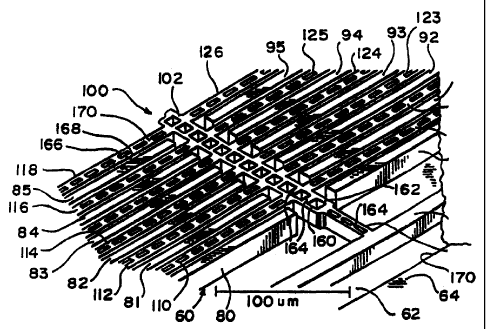
One such structure made by a method of this invention is illustrated in
the top plan view in Fig. 9, to which reference is now made. The first
lithography step described above defines the complex structural features of
the
accelerometer of the present invention, generally indicated at 60, and these
features are produced within a cavity 62 formed in substrate 64 during the
trench etch steps described above. The process produces vertical side walls
66,
68, 70, and 72 for the cavity 62, with the surrounding substrate 64 providing
the mechanical support for the fixed sensor portion of the accelerometer, as
well as desired circuitry (not shown) for controlling and/or sensing the
motion
of the movable portion of the accelerometer. The sensor portion is connected
to the side walls 68 and 72 of the cavity 62 and includes a pair of support
beams 74 and 76, respectively, which are incorporated as a part of the side
walls, or which may be cantilevered therefrom to extend inwardly into the
cavity 62. Beam 74 is connected to a plurality of stationary fingers 80
through
87, which may be solid mesa structures extending upwardly from the floor of
cavity 62, or may be cantilevered, released beams of the type illustrated in
Fig. 8. Stationary fingers 80-87 extend perpendicularly to support beam 74,
are parallel to each other, and their top surfaces lie in a common horizontal
plane above the floor of cavity 62. Stationary fingers 80-87 include a layer
of
oxide so that the capacitive plates which they carry are electrically isolated
from the substrate floor, and the fingers extend toward and terminate near an
axial center line of the cavity 62. Stationary fingers 80 through 87 are fixed
so
that they are relatively stiff and inflexible, have a high aspect ratio, and,
as
illustrated in Fig. 8, are covered with a coating of electrically conductive
CA 02232409 1998-03-17
-35-
material such as aluminum to form vertical capacitive plates. The aluminum
coating also provides electrical connection between the side wall capacitive
plates on each of the fingers 80-87 and an outlet connector pad 88, preferably
located on the top surface of substrate 64 and insulated therefrom, as
described
above.
In similar manner, beam 76 is secured to wall 68 of cavity 62,
preferably at a location diametrically opposite to the location of beam 74,
with
a plurality of laterally extending spaced fingers 90-97 extending inwardly
from
beam 76 toward the center axis of the cavity 62. As with fingers 80-87, the
fingers 90-97 are parallel to each other, may be mesa structures extending
upwardly from the cavity floor, or may be released from the floor so as to be
cantilevered to the beam 76. The top surfaces of fingers 90-97 lie in the
horizontal plane of fingers 80-87. Each of the fingers 90-97 is covered with a
suitable insulating coating and a conductive coating such as aluminum, whereby
the side walls of the beams form vertical capacitive plates. Again, the
conductive coating on each of the fingers 90-97 is connected electrically to
an
output connector pad 98 on the top surface of substrate 64 by which an
electrical connection can be made from the fixed capacitive plates to suitable
external electrical circuitry which may be incorporated in the substrate wafer
64
or which may be external thereto.
The accelerometer 60 also includes a movable central mass portion
generally indicated at 100 which can be fabricated at the same time the
inwardly-extending stationary fingers 80-87 and 90-97 are fabricated. The
movable portion 100 includes an axially-extending support beam 102 between
the terminal ends of the fingers 80-87 and 90-97. Beam 102 serves as a
backbone supporting a plurality of laterally outwardly extending
fingers 110-117 which are interleaved with the inwardly extending
CA 02232409 1998-03-17
- 36-
fingers 80-87, and further includes outwardly extending fingers 120-127
interleaved with inwardly extending fixed fingers 90-97. Preferably,
fingers 110-117 are laterally opposed to fingers 120-127 and lie in the
horizontal plane of fingers 80-87 and 90-97, but it will be apparent that they
can be relatively offset, if desired. The outwardly extending fingers are
parallel
to, and extend substantially the entire length of, the corresponding adjacent
inwardly extending fingers, the terminal ends of the outwardly extending
fingers terminating near, but just short of, the support beams 74 and 76.
Axial beam 102 and lateral fingers 110-117 and 120-127 may be
fabricated in accordance with the process described above with respect to
Figs. 4-8, and thus are released from the underlying substrate 64 for free
movement with respect thereto. The movable structure 100, consisting of the
axial beam and lateral fingers, is suspended within cavity 62 by movable
supports at opposite ends of the structure. Thus, the left-hand end 130, as
viewed in Fig. 9, is secured to, or preferably is fabricated integrally with,
a
laterally extending spring support beam 132.
The support beam 132 is flexible in the plane of the accelerometer
structure to permit axial motion of beam 102 in the direction of arrow 134.
Support beam 132 is secured at its outermost ends to the substrate adjacent
connector pads 136 and 138. The beam 132 serves as a restoring spring which
tends to hold the beam 102, and thus the accelerometer moving structure 100,
in a predetermined rest position with the opposed fixed and movable fingers
spaced apart as required. The spring provides a predetermined resistance to
motion, depending upon the dimensions and thus the flexibility of beam 132.
It will be appreciated that the support beam 132 can be made to have a
desired length and predetermined cross section in order to provide a desired
degree of sensitivity to an applied acceleration. The degree of spring
flexibility,
CA 02232409 1998-03-17
-37-
or lack thereof, is one of the determining factors (along with mass) of an
accelerometer's range of operation and sensitivity. In accordance with this
aspect of the invention, the ability to predetermine the cross section and
response or resonant frequency of support beam 132 enables an accelerometer
to be customized to have an optimal sensitivity for a specific application.
Beam 132 is fabricated in the manner described above with respect to
Figs. 4-8, and is released from the underlying substrate material in the
cavity 62
for free motion above the floor of the cavity. The spring support beam is
coated with an insulating layer and a conductive material such as aluminum so
that it can be connected to external circuitry by way of connector pads 136
and
138, which are insulated from the underlying substrate 64.
In similar manner, the opposite end 140 of beam 102 is connected to a
laterally extending spring support beam 142 which serves as a second spring
for suspending the movable element 100 in its rest position and for allowing
axial motion in the direction of arrows 134. The outermost ends of spring 142
are connected to the substrate 64 adjacent corresponding connector pads 146
and 148 which are insulated from the substrate and are provided with an
aluminum or other conductive coating for electrical connection of the beam to
suitable external circuitry.
As is illustrated in Fig. 10, which is an expanded view of a portion of
the device of Fig. 9, the movable assembly 100 of the accelerometer 60 can be
a double beam structure to provide extra stiffness and strength to this part
of
the device. As illustrated, the axial support beam 102, or backbone, consists
of
two parallel longitudinal beams 160 and 162 joined by a multiplicity of
interconnecting bridges 164 which serve as cross-braces. Similarly, each of
the
laterally extending fingers consists of a pair of parallel, closely-spaced
beams
such as the beams 166 and 168 illustrated for beam 118 and a multiplicity of
CA 02232409 1998-03-17
- 38-
cross braces, or bridges 170. This double-beam construction provides a high
degree of stiffness for the moving element 100 so that the entire element
moves
unitarily under accelerating forces without flexure of the beam 102 or the
fingers 110-117 or 120-127 to provide accurate measurements of the change of
capacitance between opposed plates on the adjacent fixed and movable finger
side walls.
Typically, in the microstructure of the present invention, each of the
fixed fingers 80-87 and 90-97 is between about 5-15 m in height depending
on whether it is a mesa-type structure or is cantilevered, is about 4 gm in
width, and may be 300 or more micrometers in length. If these fingers are
cantilevered they preferably are spaced about 2 to 10 m above the floor of
the
cavity 62. The spacing between adjacent fingers can be unequal where the
acceleration is expected to be high in one direction, so that between adjacent
fixed and movable fingers at rest, such as fingers 80 and 110, the spacing may
be about 2 m, while the distance between fingers I 10 and 81 may be 8 m.
The individual beams making up the parallel sets of beams in the movable
element 100 preferably will be somewhat thinner than the fixed beams and may
be less than 1 gm in width, although the total width of the pair of beams for
each movable finger may be somewhat greater than the width of a fixed finger.
In one form of the invention, as many as 80 individual interleaved capacitor
fingers may be provided.
The end return springs 132 and 142 may have the same general
thickness and height and thus the same cross-section and aspect ratio as the
released fingers. The two return springs are dimensioned to provide the
resilience desired for holding the movable element 100 in place, while
allowing
quick and sensitive response to accelerating forces. The high aspect ratio of
the springs insures that they will have greater flexibility in the axial
direction
CA 02232409 1998-03-17
- 39-
indicated by arrows 134 and 144, than in the vertical direction, perpendicular
to
the common plane of the axial beam 102 and the lateral fingers 110-117 and
120-127. In one embodiment of the invention, the stiffness in the axial
direction of beam 102 was 0.97 N/m while the out-of-plane stiffness, resulting
from the high aspect ratio springs, was 128 N/m.
If desired, an additional masking step, following the process of Figs. 4-
8, can be used to remove the side wall oxide and metal films from the linear
springs 132 and 142. Because the lateral spring constant (in the direction of
arrows 134 and 144) varies with the cube of the beam width, the removal of
the side wall films can reduce the lateral (in the direction of the axis of
movement) spring constant by up to two orders of magnitude. A further
control over the spring constant is obtained by varying the width of the
spring
beams by regulating the width of the silicon.
The capacitor plates on the side walls of the fixed fingers are connected
to each other and to connectors 88 and 98, as noted above, while the
capacitors formed on the side walls of the movable fingers are connected to
each other and through the metal coating on the axial beam 102 and the
metallized top surface of spring beam 132 to connector pad 136. The
connectors 88, 98 and 136 are connected to suitable circuitry, which may
include a source of potential 172, for example, which may be an alternating
excitation source. When the structure is subjected to an accelerating force,
the
movable element 100 shifts with respect to the fixed fingers 80-87 and 90-97,
the movable fingers each moving toward or away from the corresponding
adjacent fixed fingers. This motion results in a variable capacitance which
can
be determined by measuring changes in the output voltage at connectors 88 and
98 to determine the displacement of the mass of the movable element 100.
CA 02232409 1998-03-17
-40-
The mass of the movable element 100 preferably is on the order of
1.0 nkg. If it is assumed that the frequency of the accelerating force is
significantly lower than the natural frequency of the device, and that the
lateral
movable fingers and the axial beam 102 are orders of magnitude stiffer than
the
restoring springs 132 and 142, the change in separation between opposed
plates on the fixed and movable fingers can be approximated with a simple
spring-mass model and Newton's second law. From this a deformation of
13 nm for an acceleration of 9.8 m/sz can be expected, and since this
deformation is small compared to the initial two-micron separation between the
capacitor plates, the parallel plate approximation for the capacitance can be
accurately expressed using the following equation:
E
C=( )(1- ma) Eq. 1
do kdo
where m is the mass of the device, k is the lateral spring constant, A is the
area
of the plates, do is the initial separation, and a is the acceleration. The
capacitance may be measured by applying a 100 kHz, 155 mV carrier signal
from source 172 through the device. The output current from the pads 88 and
98 is amplitude modulated by the change in capacitance caused by the applied
acceleration. The magnitude of the peaks which represent the acceleration is
as
follows:
Vo='/2c.),CoVRtr(ma)( 1 )
k do
Eq. 2
where V; is the carrier amplitude, Rn. is the transresistance, C. is the DC
capacitance, c.a, is the carrier frequency, k is the spring constant, m is the
mass
CA 02232409 1998-03-17
-41-
of the device, and a is the acceleration. Experimental data show that the
output
voltage is linearly related to the acceleration.
Additional mass can be provided for the moving structure 100, if
desired, by enlarging the axial beam 102, as illustrated in Fig. 11. In the
embodiment there illustrated, accelerometer 180 includes a plurality of fixed
fingers 182 extending inwardly from a surrounding substrate, generally
indicated at 184. The fingers 182 may extend from both sides of the device,
the fingers lying in a common plane and being spaced apart to receive the
movable fingers 186 of a movable element generally indicated at 188. The
movable element is suspended at its opposite ends by linear springs 190 and
192, in the manner described with respect to Fig. 9, so that the movable
fingers 186 lie in the plane of the stationary fingers 182 and are movable in
that
plane with respect to the stationary fingers. The additional mass is provided
by
a grid 194 which takes the place of the longitudinal beam 102 in the device of
Fig. 9. This grid may be fabricated in the form of a plurality of individual
longitudinal beams and lateral spacers, or may be in the form of a plurality
of
parallel beams covered by a layer of material such as tungsten in the manner
illustrated in Fig. 12. A layer 196 of tungsten may be applied to a plurality
of
released beams 198, 199, 200, to provide an increased mass, the tungsten
covering a selected portion of the grid formed by the underlying
beams 198-200, for example, and filling in the inter-beam spaces to produce a
thick conformal blanket. The size and thickness of the grid 194 or the
layer 196 is selected to provide the mass required for the accelerometer
function.
As illustrated in Fig. 11, in order to provide the additional mass
required, it may be necessary to widen the spacing between the terminal ends
of
the fixed fingers on both sides of the accelerometer device. It will be
CA 02232409 1998-03-17
-42-
understood that the exact dimensions will be selected in accordance with the
sensitivity required for the forces that are to be measured.
The accelerometers illustrated in Figs. 9, 10, and 11 are referred to as
single-ended accelerometers, since motion of beam 102 in either direction
along
its axis causes the spacing between each of the movable fingers and its
corresponding stationary finger to change in the same direction. It will be
understood that the device could also sense motion in a vertical direction,
toward and away from the floor of cavity 62, by changing the dimensions of the
suspension springs 132 and 142 to allow vertical motion. In this case, the
movable and fixed fingers would be equally spaced on both sides of each
finger,
by a distance of, for example, 2 m.
Fig. 13 illustrates a modified version of the accelerometer which may be
referred to as a differential, or double-ended device. As there illustrated,
accelerometer 210 includes two stationary portions 212 and 214, both of which
interface with corresponding laterally extending fingers forming part of a
movable element 216. As illustrated, section 212 has laterally inwardly
extending stationary fingers 218 and 220 extending inwardly from opposite
sides of the accelerometer and spaced apart to receive interleaved movable
fingers 222 and 224, respectively, which extend laterally outwardly from a
central, axially extending support beam 226.
In similar manner, the section 214 includes rigid fingers 228 and 230
extending inwardly from opposite sides thereof and interleaved movable
fingers 232 and 234 extending laterally outwardly from beam 226. Opposite
ends of beam 226 are supported by linear springs 236 and 238, respectively, in
the manner described above.
The stationary fingers 218 and 220 are connected to a first outlet
connector pad 240 while stationary fingers 228 and 230 are connected to a
CA 02232409 1998-03-17
- 43-
second outlet connector pad 242. The movable structure 216 is connected to a
single voltage supply pad 244.
The movable fingers in section 212 of the accelerometer are on the
right-hand side of their corresponding stationary fingers (as viewed in the
Fig.)
while the movable fingers in section 214 are mounted on the left-hand side of
their corresponding fingers 228. Accordingly, motion of the movable
element 216 to the left, as viewed in the Fig., causes fingers 218 and 222 to
move closer together, while at the same time causing fingers 228 and 232 to
move further apart. This provides a differential or change in capacitance
between the respective plates, and provides a differential voltage change at
pads 240 and 242 so as to increase the overall sensitivity of the
accelerometer
for a given amount of longitudinal motion.
As indicated above, the sensitivity of the accelerometer can be selected
by properly dimensioning the thickness, height and length of the suspension
springs at the ends of the movable element. It will be recognized that once
fabricated, the mechanical structure will have a fixed natural, or resonant,
frequency and a response bandwidth which is limited by the natural frequency
of that structure. Thus, the range of input frequencies that the sensor can
accurately measure is limited by its mechanical structure. However, in
accordance with a further feature of the present invention, a control
structure is
provided for electrically or electromechanically varying the stiffness of the
restoring springs. This advantageously achieves precise control of the
resonant
frequency of the device and increases the range of frequencies that the sensor
can accurately measure.
One structure for varying the stiffness of the spring and thus the
resonant frequency of the accelerometer is illustrated in Figs. 14 and 15. As
there illustrated, an accelerometer 250 includes a movable element 252 having
CA 02232409 1998-03-17
- 44-
an axial support beam 254 carrying a plurality of laterally outwardly
extending
fingers 256. As discussed above, the fingers 256 are interleaved with inwardly
extending stationary fingers 258 mounted as cantilevers on a substrate 260.
The support beam 254 is mounted at its opposite ends to laterally extending
linear restoring springs 262 and 264, both of which are connected at their
outer
ends to a fixed support adjacent connector pads such as the pads 266 and 268.
Control of the flexibility of springs 262 and 264, and thus of the resonant
frequency of the structure, is provided by a pair of capacitive drivers 270
and
272, respectively. Driver 270 is illustrated as including a first plate 274
fixed to
the return spring 262 and a second, spaced plate 276 fixedly mounted to a
support pad 278. The driver is electrically connected by way of pad 278 and a
connector line 280 to a suitable source of control voltage. By varying the
voltage applied to line 280, the potential across plates 274 and 276 can be
varied, thereby controlling the force between these plates and thereby
regulating the accelerating force required to enable the movable support
beam 254 to move plate 274 with respect to plate 276. Since that motion is
due to the accelerating forces applied to the accelerometer, the voltage
applied
to line 280 controls the effective stiffness of the spring and thus the
sensitivity
of the accelerometer. In similar manner, a voltage applied by way of line 282
to capacitor 272 controls the stiffness of spring 264.
The voltages applied to the two drivers 270 and 272 can be used to
reduce the stiffness of the springs 262 and 264 by selecting the voltages to
oppose each other so that a force is applied to one of the drivers to move
spring 262 to the left, and a force is applied to the other capacitor to move
spring 264 to the right. If an accelerating force initiates motion of the
structure
toward the left, for example (see Fig. 15), the capacitance of capacitor 270
will
increase and that of capacitor 272 will decrease. As a result, the new force
on
CA 02232409 1998-03-17
-45-
the element 252 due to the voltage applied to capacitors 270 and 272 will be
towards the left, and this will aid the accelerating force, thereby producing
a
net reduction in the external force required to shift the movable fingers 256
with respect to the stationary fingers 258. This increases the sensitivity of
the
device and decreases the natural frequency.
Although drivers 270 and 272 are illustrated as parallel plate capacitors,
it will be understood that comb-type capacitors can also be substituted for
the
plate-type capacitors to control the motion of the springs.
An increase in the stiffness of the support springs can be obtained in the
manner illustrated in Fig. 16 wherein an accelerometer 290 includes a movable
element 292 having laterally outwardly extending fingers 294 extending from a
central, axially extending support beam 296. Beam 296 is connected at its
opposite ends to laterally extending linear suspension springs 298 and 300
which are fixed at their outer ends and which are flexible to permit
longitudinal
motion of beam 296 and corresponding motion of the fingers 294 with respect
to stationary interleaved fingers (not shown). To increase the stiffness of
the
springs 298 and 300, a pair of control capacitors 302 and 304 are provided. In
this embodiment, capacitor 302 includes a first comb-shaped plate 306
connected to the movable element 292 and a second, opposed comb-shaped
plate 308 connected to a fixed pad 310 on the substrate in which the
accelerometer is mounted. Capacitor 304 is similarly constructed.
A force applied to the accelerometer to cause the movable element 292
to shift towards the left (as viewed in Fig. 16) will cause plate 306 to shift
towards the left with respect to the fixed plate 308. A voltage applied across
those plates will tend to restore the plate 306 to its rest position
(illustrated in
the Fig.). The greater the accelerating force applied to the movable
element 292, the greater the displacement of plate 306 with respect to
CA 02232409 1998-03-17
-46-
plate 308. By controlling the voltage applied across the plates the restoring
force can be controlled to provide the desired effective stiffness for the
springs 298 and 300. The minimum voltage required to hold the movable
element 292 in place is a measure of the accelerating force applied to that
element.
Figs. 17 and 18 illustrate an electromechanical method for increasing
the stiffness of the return springs for the accelerometer. As there
illustrated,
the accelerometer 320 includes a movable portion 322 having, as before, an
axial support beam 324 and a plurality of laterally outwardly extending
fingers 326. The opposite ends of the beam 324 are supported by laterally
extending linear suspension springs 328 and 330 which are supported at their
outermost ends on fixed pads such as the pads 332 and 334. Adjacent each of
the springs 328 and 330 is a pair of clamping capacitors such as the
capacitors 336 and 338 adjacent spring 328. These two capacitors are
mounted on a flexible support beam 340 which is, in turn, mounted at its
center
by way of arm 342 to a fixed pad 344. A voltage may be applied to the two
capacitors 336 and 338 by way of an input line 346 and electrically conductive
coatings on pad 344 and beams 340 and 342. An application of a suitable
voltage draws the plates of capacitors 336 and 338 together, as illustrated in
Fig. 18, thereby bending the support beam 340 and effectively connecting
beams 340 and 328 in parallel to thereby mechanically change the flexibility
of
beam 328. In similar manner, the flexibility of beam 330 can be changed by the
application of a voltage to capacitors 348 and 350 which are constructed in a
manner similar to that of capacitors 336 and 338. After the capacitors for
both
beams 328 and 330 are clamped, the system becomes stiffer and the natural
frequency increases, with a consequent decrease in sensitivity. It will be
understood that a layer of insulation will be included between the plates of
the
CA 02232409 1998-03-17
- 47-
clamping capacitors and the restoring springs 328 and 330 to prevent sticking
and to prevent short circuits.
In each of the embodiments illustrated herein, an active feedback system
may be incorporated to measure the capacitance between the plates on the
fixed and movable fingers caused by relative motion of the plates and to
provide a feedback voltage that can be applied to restore the movable fingers
to
their rest position. The feedback voltage is a measure of the applied force.
In
such a system, the change in capacitance due to the applied force is measured
by the current flow through the plates, for example, and this value is used to
adjust the voltage applied to the movable element to thereby hold the movable
element at its rest position with respect to the fixed structure. The feedback
voltage varies instantaneously with changes in the applied force, so the
movable element does not move, with the result that errors due to
nonlinearities caused by relative motion of the parts is eliminated, and the
accuracy and sensitivity of the system is increased. Such a feedback system is
illustrated diagrammatically in Fig. 19 where a variable voltage supply 360
supplies potential to the movable plates 362 of the accelerometer. The current
flow between the variable plates 362 and the stationary plates 364 is measured
by a current sensor 366 and compared to a reference value. A difference signal
is applied by way of line 368 to regulate the variable supply 360 to maintain
a
predetermined spacing between the fixed and movable plates. The value of the
signa1368 may be used to determine the value of the accelerating force applied
to the movable plates 362. Such a system can be used, for example, to provide
a feedback voltage to maintain the alignment of capacitor plates 306 and 308
in
Fig. 16, or to control the voltages applied to capacitors 270 and 272 in Fig.
14.
Although the foregoing discussion has been directed to variations of
capacitance caused by motion of the movable element; for example,
CA 02232409 1998-03-17
-48-
element 100 in Fig. 9, in the plane of the capacitor plates, it will be
understood
that motion perpendicular to that plane can also be measured, since there is a
capacitance between the capacitor plates carried by the moving fingers and the
underlying substrate or a metal layer or that substrate. This is illustrated
in
Fig. 8, where metal layer 48 can serve as a ground plate with respect to the
metal layer 46 on the beam 42. The capacitance between these metal layers can
be used to detect motion perpendicular to the plane of the fingers so that the
accelerometer is three dimensional. Although the layer 48 is shown as being on
the semiconductive substrate 10, it will be understood that an insulating
layer
can be provided on the floor of the trenches before the metal layer is applied
so
as to insulate layer 48 from the underlying substrate.
The fabrication process described above can also be used for making a
torsional accelerometer such as that illustrated in Fig. 20. In the embodiment
there illustrated, a movable element, or beam, 380 is located within a
cavity 382 in the substrate, and is mounted for rotational motion about the
axis 383 of a shaft 384. As illustrated in Fig. 21, shaft 384 extends across
the
cavity 382 to mount the movable element 380 on the side walls 386 and 388
defining the cavity, which is formed within substrate 390. As most clearly
seen
in Fig. 20, the movable element 380 may be fabricated to be asymmetrical with
respect to the shaft 384 so that the left hand side, as viewed in Figs. 20 and
21,
of the movable element is more massive than the right hand side. This uneven
distribution of mass causes the movable element 380 to twist around the axis
of
shaft 384 when the movable element is subject to a vertical motion in the
direction of arrows 392.
The twisting motion produced by rotation of the movable element 380
about the axis of shaft 384 is resisted by the spring action of the shaft
which
tends to restore element 380 to its neutral horizontal position. Motion of
CA 02232409 1998-03-17
- 49-
element 380 may be detected by corresponding capacitor plates located on the
movable device and on the surrounding substrate, as previously discussed.
Thus, for example, a conductive layer 394 on the movable element 380 may be
used to form a common plate for each of a pair of motion sensing capacitors.
The plate 394 may be connected to external circuitry by way of metallic
layer 396 on the shaft 384 leading, for example, to a connector pad 398 on the
surface of the substrate. As illustrated in Fig. 20, the plate 394 extends
vertically down the sides of the movable element 380, at 400 and 402 on the
left and right vertical walls, respectively, of element 380.
The vertical walls 400 and 402 form movable capacitor plates which are
adjacent corresponding spaced stationary plates 404 and 406, respectively, to
form sensing capacitors 408 and 409. Electrode plate 404 is formed on the top
of substrate 390 and extends over the side wa11411 of the cavity. In similar
manner, the electrode 406 is located on the surface of the substrate and
extends
over the side wal1411 of the cavity so that motion of the movable element 380
shifts capacitor element 400 with respect to corresponding element 404 and
shifts element 402 with respect to corresponding element 406. The relative
motion of the plates changes the capacitance of both capacitor 408 and
capacitor 409, and these changes can be detected by suitable circuitry
connected to the various capacitor plates by way of the electrodes on the
surface of the substrate. The element 380 and the capacitors 408 and 409 form
a sensitive accelerometer capable of measuring small changes in capacitance to
provide a sensitive measurement of vertical motion or acceleration.
It will be understood that the movable element 380 may be fabricated to
be symmetrical with the shaft 384 so that the mass on each side of the shaft
is
the same. In this situation, vertical motion or acceleration of the device in
the
direction of arrows 392 will result in bending of the shaft 384 in a vertical
CA 02232409 1998-03-17
- 50-
direction, rather than rotation. However, this motion can also be measured by
the capacitors, as discussed above.
Through conventional masking techniques, material can be added to the
movable element 380 on one side or the other of the axis of shaft 384 to
adjust
the torsional forces exerted upon the element as a result of vertical motion
of
the substrate. The material added can be tungsten, for example, added to the
top surface of the element 380 through a mask to change the balance of the
element 380 and thus to change the characteristics of the accelerometer.
It will be understood that rotational, or torsional, motion imposed on
the substrate 390 for example, motion about the axis of shaft 384, can also be
measured by the device of Figs. 20 and 21. Thus, rotation of the substrate 390
in a clockwise direction about the shaft 384 will result in relative motion
between the plates 400 and 404 and between plates 402 and 406 to produce a
change in capacitance which can be measured, as discussed above.
Torsional motion also can be measured by the device illustrated in
Figs. 22 and 23, wherein a central, elongated support beam, or arm is mounted
on a vertical shaft for rotational motion in a horizontal plane about the axis
of
the vertical shaft. As illustrated in these Fig.s, a substrate 420
incorporates a
cavity 422, which in this case is illustrated as being circular, with a
vertical
post, or shaft, 424 extending upwardly from the floor 426 of the cavity.
Fabricated on the top end of the shaft is an accelerometer sensor element 428,
which in this case is in the shape of an elongated beam, or arm 429 extending
across the cavity and movable in a horizontal plane perpendicular to the axis
of
shaft 424. The arm 429 terminates at a pair of laterally extending, arcuate
fingers 430 and 432 unitarily formed with the arm 429. The fingers 430 and
432 act as inertial weights for the movable arm 429 so that when a rotational,
or torsional force having a component in the horizontal plane of arm 429 is
CA 02232409 1998-03-17
-51-
imposed on the substrate 420, for example in the direction of arrows 434, the
inertia of lateral fingers 430 and 432 will produce a twisting motion about
the
axis of shaft 424 which is resisted by the spring action of the shaft. The
length
and thickness of the fingers 430 and 432, as well as the length and thickness
of
arm 429, including an enlarged hub portion 436, determine the sensitivity of
the
device to torsional forces.
As noted above with respect to Fig. 20, the device may be modified to
change the sensitivity of the device and the applied accelerometer force to
which the sensor element responds by adding an additional metal layer to the
arm 429 as well as to the fingers 430 and 432, the use of suitable masks
permitting accurate control of the placement of such additional material. The
shaft 424 acts as a flexible restoring spring for the sensor element 428,
urging
the element toward its normal rest position.
To sense the relative motion of the arm 429 with respect to the
substrate 420, four pairs of capacitor plates are provided, plates 438 and 440
and plates 442 and 444 being positioned on opposite sides of corresponding
ends of lateral finger 430, and plates 446 and 448 and 450 and 452 being
positioned on opposite sides of corresponding ends of lateral finger 432. The
capacitor plates, in the illustrated embodiment, are arcuate and spaced
sufficiently apart to permit motion of the arcuate fingers 430 and 432 between
the respective pairs of plates, with the plates themselves preferably being
concentric with the axis of shaft 424.
Rotational motion of the arm 429 with respect to the substrate 420
causes each of the fingers 430 and 432 to move further between one of its
associated pair of capacitor plates and to move out of the other of its
associated pair of capacitor plates to differentially change the capacitance
measured by each pair. This permits a highly sensitive measurement of
CA 02232409 1998-03-17
- 52-
capacitance changes upon the application of rotational forces, thereby
providing a very sensitive torsional accelerometer.
The stationary plates for the capacitor pairs are connected to external
circuitry through suitable conductive strips on the substrate, as previously
discussed. Thus, for example, the stationary plates 438 and 442 are connected
to a conductive strip, or layer, 460 while plates 446 and 450 are connected to
conductive strip 462 on the top surface of substrate 420. Stationary
capacitive
plates 440 and 448 are connected to conductive strip 464 and plates 444 and
452 are connected to conductive strip 466, respectively. Strips 464 and 466
extend along the floor 426 of the cavity 422, up respective side walls of the
cavity and across the surface of the substrate. It will be understood that
other
arrangements of the conductive strips may be provided, as desired. Movement
of the fingers 430 and 432 between the pairs of capacitive plates changes the
capacitance therebetween and such changes are detectable by suitable circuitry
(not shown) connected to the conductive strips.
Although the plates 438, 442, 446, and 450 are illustrated as being
fabricated on the side wall of cavity 442, it will be understood that they may
be
free standing, or may consist simply of a conductive layer of metal formed on
the surface of the cavity wall. Free standing capacitor plates are illustrated
in
Fig. 24, which illustrates an embodiment of the invention wherein the
cavity 422' in substrate 420' is enlarged to receive extensions of the movable
arm 429'. In the embodiment of Fig. 24, elements in common with the device
of Fig. 22 are illustrated by primed numbers. Thus, free standing capacitor
plates 438' and 442' are connected to a conductor 460', plates 440' and 448'
are
connected to conductor 464', plates 446' and 450' are connected to
conductor 462', and plates 444' and 452' are connected to conductor 466', the
conductors leading to suitable external circuitry (not shown) as previously
CA 02232409 1998-03-17
- 53-
discussed. In this case, however, the strips 460' and 462' may be located on
the
cavity floor instead of on the top surface of the substrate.
In the embodiment of Fig. 24, the movable element 428' includes a pair
of extension weights 470 and 472 mounted by way of extension arms 474 and
476, respectively, to opposite ends of movable arm 429'. The weights 470 and
472 are enlarged masses which provide greater inertia to the movable
element 428 to increase the sensitivity of the device to torsional or
rotational
forces, thereby providing a more sensitive torsional accelerometer. The
weights 470 and 472 are fabricated from the substrate material in the manner
described above, and may be covered by metal to a thickness sufficient to
provide the desired mass, and thus the desired sensitivity, for the device.
Accelerometer Uses
Accelerometers of this invention may be used in vehicles such as cars,
buses, and trucks to deploy airbags and control suspension movement, steering,
and braking and as part of an inertial navigation system. Equivalent
accelerometers also may be used in vehicles such as aircraft, ships, and
submarines to measure acceleration in different directions and to control the
movement of those craft or the deployment of safety devices such as airbags or
the anti-blackout device used by pilots. While these different uses may
require
accelerometers of differing design and response characteristics, such
accelerometers nevertheless could be constructed incorporating the aspects of
the present invention.
For example, a micromechanical accelerometer used to deploy an airbag
typically will have moving parts of relatively high mass and/or springs having
large spring constants. The accelerometer is usually attached to signal-
conditioning electronics to convert either a voltage change associated with
change in capacitance, or a change in current required to maintain constant
CA 02232409 2006-02-15
54-
voltage into a signal that indicates the measured acceleration. The output
signal can be, for example, a voltage, a frequency, or a signal amplitude that
varies with acceleration. The output signal also can be a signal that
indicates
that a preset acceleration has been met or exceeded. The output signal is used
by other electronics to deploy the airbag when an acceleration of a certain
magnitude is measured in a specified direction. Examples of these systems are
disclosed in U.S. Patent Nos. 5,436,838 and 5,411,289.
An accelerometer used to measure pitch or yaw or vehicle suspension
movement will typically have moving parts of low mass and springs with small
spring constants. The accelerometer is connected to signal conditioning
circuitry in a well known manner as-discussed above, and the signal is sent to
a
read-out device or to other components that control the suspension of the
vehicle. These accelerometers also can be used in steering systems, for
example, to measure the lateral acceleration of a vehicle due to wind and to
control the steering in order to correct for the wind forces, or to provide a
variable steering system. Examples of these systems are disclosed in U.S.
Patent Nos. 5,348,111, 5,295,074, Re. 34,628, and 4,625,993,.
Similarly, an accelerometer of this invention may be used to measure
the acceleration of a vehicle, and differences in acceleration may be used to
control the power applied to the wheel (in the case of traction control) or
the
braking force applied to a particular wheel (in the case of traction control
or
anti-lock braking). Examples of these systems are disclosed in U: S. Patent
Nos. 5,454,630, 5,315,518 and 5,275,474.
CA 02232409 1998-03-17
- 55-
An accelerometer of this invention can be fabricated in the same
substrate as electronic components that are used to process the signal from
the
accelerometer or other electronic components that are to be placed on the same
substrate. For example, an accelerometer, optional signal-conditioning
electronics, and such VLSI circuitry as airbag-deployment electronics all may
be supplied as an integrated unit by fabricating all of these components on
one
substrate. This method of manufacturing provides smaller electronic packages
having greater reliability and consistency than can be provided by
conventional
capacitive accelerometers. The electronics associated with the accelerometer
may be completely fabricated before the substrate is etched to form an
accelerometer. A mask protects the electronics from etching when forming
the accelerometer.
Alternatively, the electronics associated with the accelerometer may be
fabricated after the substrate is etched to form an accelerometer. A mask then
protects the accelerometer when etching or otherwise forming the electronic
components. However, the metal deposition for the accelerometer would have
to be done after the initial high temperature steps for the electronics
fabrication.
Reactive-ion etching allows fabrication of other micromechanical
structures from the same substrate as electronic components and/or an
accelerometer are fabricated. The combination of low reaction temperatures
and use of masks protects the micromechanical structure and/or electronics
being formed from other processing steps that would damage the particular
component being formed, if low temperature or a mask were not being used.
The micromechanical structure is one that can be at least partially etched
using
reactive-ion etching and which is not rendered inoperative for its intended
CA 02232409 2006-02-15
j f
- 56-
function because of process steps required to form other components to be
present on the same substrate.
.umm of Advantages of Accelerometers of This Invention
Plasma or reactive ion etching offers a solution to the limitations of bulk
and surface micromachining for many commercially important applications.
See, for example, Z. Lisa Zhang and Noel C. MacDonald, "A RIE Process For
Submicron, Silicon Electromechanical Structures," J. Micromech. Microeng. 2
(1992), pp. 31-38; See also, Kevin A. Shaw, Z. Lisa Zhang and Noel C.
MacDonald, "SCREAM I: A Single Mask, Single-Crystal Silicon, Reactive Ion
Etching Process For Microelectromechanical Structures," Sensors And
Actuators, 40 (1994), pp. 63-70; U.S. Patent Nos. 5,198,390, 5,316,979 and
5,393,375, and U.S. patent No. 5,719,073 filed September 27, 1994, entitled
"Microstructures and Single Mask, Single-Crystal Process for Fabrication
Thereof,"
and U.S. patent No. 5,628,917, filed April 11, 1995, entitled "Masking Process
For
Fabricating Ultra-High Aspect Ratio, Water-Free Micro-Opto-Electromechanical
Structures." The following table summarizes strengths and weaknesses of the
different
fabrication technologies discussed above.
CA 02232409 1998-03-17
- 57-
MEMS Possible Mechanical Process
Fabrication Description Device Mechanical Structure Integration
Technology Geometries Material Aspect-Ratio with Micro-
electronics
Bulk micro- Anisotropic very limited single crystal typically low; poor
machining chemical etchant shapes; a silicon special cases
(e.g. KOH) is function of the can be very
used to define crystal planes high
structures
bounded by
certain crystal
planes. Wafer
bonding or ion
implantation is
often used to
form etch stops.
Surface Poly-crystalline arbitrary polysilicon low fair
micro- silicon is shapes but
machining deposited on a limited in
sacrificial layer vertical height
of silicon
dioxide.
Mechanical
structures are
formed in the
polysilicon and
then the
sacrificial layer is
etched away to
release them.
Plasma or A sequence of arbitrary single crystal high excellent
reactive ion anisotropic and silicon
etching isotropic reactive
ion etches is used
to fabricate
released
mechanical
micro-structures
in single crystal
silicon.
Table 1.
CA 02232409 1998-03-17
- 58-
According to an aspect of the invention, reactive-ion or plasma etching,
using dry etching techniques, provides a number of advantages over
conventional methods for fabricating structures for a microelectrochemical
accelerometer.
The mechanical structures can be formed in or from single crystal
silicon or other substrate and in or from a single wafer. The use of single
crystal silicon eliminates grain boundaries and provides uniform mechanical
characteristics and enables resonant frequency to be closely controlled. The
use of a single crystal silicon released structure also provides an improved
sensing element. Active signal conditioning circuitry such as transistors also
can be formed directly in the beams or released structures comprised of single
crystal silicon which form the sensing elements. This substantially eliminates
nonlinearity or inaccuracies in measurement due to parasitic capacitance and
thermal or mechanical strain.
The height of structures is controlled by the depth of the plasma etch
into the silicon, rather than by implantation of an impurity into the silicon
or by
depositing or bonding an additional structural layer on the substrate. This
enables very thick released structures to be created with high aspect ratios,
on
an order of 6:1 up to 100:1 or greater. Such high aspect ratio sensing
elements
are characterized by high stability and insensitivity to undesirable
transverse
acceleration. High aspect ratio released structures also provide greatly
increased capacitance for sensing smaller acceleration vectors.
Reactive-ion etching eliminates the problem of inherent stress in the
mechanical structures, as is present in, e.g., polycrystalline silicon, since
the
mechanical structures can be formed from initially stress-free bulk silicon.
Thus, an accelerometer made by this process can achieve greatly improved
sensitivity and an enhanced response to smaller acceleration vectors. This
CA 02232409 1998-03-17
-59-
would enable an accelerometer made in accordance with this aspect of the
invention to be useful in a range of 0.1 to 1 g.
Another important advantage of the invention is that the geometry of
the accelerometer can be determined independently of crystal orientation,
thereby enabling complex shapes and structures to be made.
The entire accelerometer fabrication process of the present invention is
compatible with and scalable with conventional VLSI integrated circuit
processes. This enables fabrication of signal conditioning circuitry or other
devices on the same silicon wafer or chip from which the micromechanical
sensing device is fabricated.
As a result of the foregoing and other advantages, accelerometers of
this invention, particularly those made with reactive ion etching, are capable
of
high accuracy and can be produced precisely with repeatable dimensions and in
high yields with commensurate low per unit costs as required by automotive
accelerometer applications. Furthermore, accelerometers of this invention can
achieve superior device performance such as high linearity, high capacitance,
and excellent phase-response to accelerations because of the variety of
geometries made possible by reactive-ion etching, the light mass and high
stiffness of the accelerometer, and the improved metal layer conformation to
the capacitively-coupled areas of the accelerometer.
A wet-chemical micromachining etch of the prior art would not be
capable of making structures such as those illustrated in Figs. 20 and 22 with
accuracy and repeatability of dimensions. As noted above, wet-chemical
etching is dependent on orienting the structure along certain crystal planes
and
timing the etch. Etching occurs at different rates along different crystal
planes.
Obtaining complex structures such as those shown in Figs. 20 and 22
requires unusually-shaped etch masks and silicon crystals free of crystal-
plane
CA 02232409 1998-03-17
- 60-
defects, as well as precise control of etch conditions and time. Silicon
crystals
often have crystal-plane defects, and etch conditions and time vary within the
processing and control limits of the equipment used. Wet-chemical etching
cannot make complex structures such as those shown in the figures accurately
and repeatably because of the inherent limitations in the wet-chemical etching
process.
Improved accelerometer performance results in part from the high
aspect-ratio mechanical structures which can be provided. The high aspect
ratios of the capacitively-coupled fingers helps to provide large surface
areas.
Prior-art micromachining is limited to making plates having an aspect ratio of
approximately 5:1 or less, because, among other reasons, prior-art
micromachining utilizes wet-chemical etching that is highly dependent upon
orienting the structure to be etched along a particular crystal plane. This
also
depends upon precise timing of an etch to prevent over-etching the length,
width, and height of the plates.
The non-uniform etching that is prevalent in wet-chemical etching also
limits the aspect ratio and length of fingers, since localized over-etching as
occurs in wet-chemical etching creates weak, delicate areas that break easily.
Reactive-ion etching permits fabricating fingers or a sense element having an
aspect ratio greater than about 4:1, preferably greater than about 6:1, and
more
preferably, greater than about 15:1.
It will be appreciated that reactive-ion etching is independent of crystal
orientation, and etch time can be used to control only the depth of an etch,
the
length and width of the etch being determined independently of the depth. Fig.
25 defines parameters of interest for the following calculations in which the
importance of the aspect-ratio (b/a) will become clear.
CA 02232409 1998-03-17
-61-
Fig. 25. Definition of Key Geometrical Parameters
In accordance with an aspect of the invention, high aspect ratio
structures are advantageous for several reasons.
As mentioned earlier, the preferred transduction mechanism for an
accelerometer is to measure a change in capacitance resulting from the
displacement of a mass under acceleration. Most often this is accomplished by
having a parallel plate capacitor configuration, such as shown in Fig. 25, in
which one plate (beam) moves relative to the other. As the capacitance of such
a structure is strongly influenced by the gap (d) between the plates, a
measurement of the capacitance provides an accurate measurement of the
displacement resulting from acceleration. Clearly an important parameter then
is the total capacitance of the device as this will determine the ultimate
sensitivity and measurement range available. The capacitance (C) of the
structure shown in Fig. 25, per unit of silicon wafer area, is given by:
Czne b L. 1z ne b 1
d a-L a d Eq. (1)
where n is the number of plate pairs, and E is the dielectric constant of the
material between the plates, typically air (8.85x10⁻¹² F/m).
If the device is to be a capacitively driven actuator, then the force
generated is a key performance factor. The force per unit area of silicon
wafer
for a comb-drive geometry actuator is given by:
F=nc b VZ . 1=ne b V2
d a-L a d-L Eq. ( 2)
where V is the voltage applied between the beams.
CA 02232409 1998-03-17
- 62-
An additional important performance factor is the stiffness of the
mechanical structures as this determines the resonant frequency of the device
and its resistance to motion out of the plane. Higher resonant frequencies
increase the operating bandwidth of the device, while high out-of-plane
stifffness precludes unwanted mechanical modes and transverse response. The
stiffness (K,) of a micromechanical beam loaded at its midpoint by a force
acting in the x-direction (as defined in Fig. 25J is given by:
K= 48EI = 4E a3 b
x L 3 L3 Eq. (3)
where E is the Young's modulus of the material (for single crystal silicon E
is
1.9x10¹¹ N/m) and I is the moment of inertia (a3b/12).
If the force acts on the top of the beam (in the z-direction), then the
"height" and "width" of the beam are reversed in Equation 3 and, therefore,
the
ratio of stiffness in the z-direction (out-of-plane) to that in the x-
direction is
given by:
K b 2
K a~ Eq. ( 4)
x
Equation 4 shows that this ratio increases as the square of the aspect-ratio.
Hence, for MEMS devices with an aspect ratio of 20:1 as can be fabricated
using reactive-ion etching versus a surface micromachined device with an
aspect-ratio of 2:1, the improvement in out-of-plane (or similarly, transverse
stiffhess, Ky/KX) is a factor of 100.
The calculations presented above for sensing capacitance and actuating
force were stated as per unit area of silicon. The relevance of this quantity
is
that the manufacturing yield of a silicon IC chip in conventional
microelectronic
device processing is essentially inversely proportional to the area of the
chip.
CA 02232409 2006-02-15
-63-
The larger the chip size the lower the yield per wafer. Hence, capacitance or
force per unit chip area provides a means for comparing surface
micromachining with reactive-ion etching for comparable manufacturing yields.
In surface micromachining, the height of the mechanical structures (b) is
determined by the thickness of the polycrystalline silicon film deposited.
Residual stress in polysilicon films establishes a practical limit of 2-4 m
for
their height, whereas, in plasma etching, the height of the structures is
determined by the depth of the reactive ion (plasma) etch. In practice these
heights can be at least 20 m. Recent research advances in plasma
micromachining suggest the possibility of structures in single crystal silicon
as
high as 100 m, that is, 20 to 50 times higher than possible with polysilicon
surface micromachining. See U. S. Patent No. 5,628,917.
The beam width (a) and separation (d) are determined by the resolution
of the lithography utilized in either surface micromachining or reactive-ion
etching. Both techniques can attain minimum feature sizes of 1.5 m and
smaller. Hence, one key distinction between conventional surface
micromachining and reactive-ion etching is the greater beam height and aspect-
ratio attainable through reactive ion etching the latter. A factor of ten
higher
beam height for reactive-ion etching (e.g. 20 m versus 2 m) results in sensing
capacitance and actuating force per unit area of silicon at least ten times
that
available with surface micromachining. Table 2 provides some representative
values. The significant advantages of reactive-ion etching are clearly
illustrated
in the right-hand two columns of the table.
CA 02232409 1998-03-17
- 64-
Surface Reactive-ion Reactive-ion
Micromachining Etching Etching
(using same (using typical
parameters as process
surface micro- capabilities)
machining other
than aspect ratio)
Beam width (a) 4 m 4 m 1.5 m
Beam height 2 m 20 m 20 gm
Beam separation (d) 1.3 m 1.3 m 1.0 m
Beam length (L) 120 m 120 m 250 m
Number of pairs n 46 46 100
Actuator volta e V 1124 V 24 V 24 V
Device capacitance (C) 0.07 pF 0.74 pF 4.4 pF
Device actuating force 0.37 gN 3.6 gN 10.2 gN
(F)
Table 2.
Table 2 is compiled from Kuehnel and Sherman, "A Surface
Micromachined Silicon Accelerometer with On-Chip Detection Circuitry,"
Sensors andActuators A 45 (1994), pp. 7-16.
The problems inherent in the limited beam height available in surface
micromachining, for example as shown in U.S. Patent No. 5,345,824, are
clearly understood from the above calculations. In the '824 patent, the device
capacitance available is very small, with the total device being -0.1pF [col.
5
line 1-2, 6]. Kuehnel and Sherman note that one-half of the transducer signal
is
lost because the lowest input capacitance signal conditioning electronics
available has -0. 1 pF of stray capacitance, i.e. on the same order as the
transducer itself, resulting in a 6dB (1/2) reduction in signal strength.
CA 02232409 1998-03-17
-65-
Using reactive-ion etching for a device with the same geometric area as
the '824 patent would result in a total capacitance of 0.7pF (Table 2, second
column). Furthermore, if a more optimal geometry were to be used when
reactive-ion etching, an accelerometer can be obtained with 4.4pF of
capacitance, that is, 44 times higher than a conventional accelerometer such
as
taught by the '824 patent. Thus, at least half of the signal strength of the
capacitor is lost from a conventional surface-micromachined accelerometer. In
contrast, less than 15% of the signal strength of the comparable reactive-ion
etched accelerometer of the present invention is lost to parasitic
capacitance.
Kuehnel and Sherman also show the limitation of a conventional
polysilicon process in terms of beam stiffness. The authors report that the
first
(lowest frequency) mechanical mode of the accelerometer sense element is out
of the plane of the wafer. The second mode is the desired in plane motion. A
structure comprising high aspect ratio beams, such as 20:1, which can be
achieved using reactive-ion etching of the present invention, would have 100
times greater out-of-plane stiffness than the '824 device (see Equation 4).
In summary, the foregoing aspects of the present invention provide an
improved microelectromechanical accelerometer incorporating a sensing
element comprising a movable, released structure formed from single crystal
silicon with low temperature reactive ion etching. Fig. 26 depicts one
embodiment of such an accelerometer. This approach overcomes the shape
and height limitations of conventional micromachining processes and achieves a
sensing element comprising higher aspect ratio capacitor plates than is
possible
with a conventional micromachining process. The capacitor plates of the
sensing element have greater mechanical stiffness due to the high aspect
ratio,
particularly if a grid type beam structure is used. This results in greater
sensitivity to acceleration vectors within a desired axis of sensitivity.
CA 02232409 1998-03-17
- 66-
Consequently, this advantageously results in substantial immunity to
transverse
forces out of the axis of sensitivity. These effects greatly improve the
signal-to-noise performance of an accelerometer according to the present
invention over conventional microelectromechanical accelerometers. The
foregoing advantages enable an accelerometer of the present invention to be
useful in the 0.1 to 1g range as opposed to the 50g range ordinarily
associated
with airbag deployment applications.
A further advantage of fabricating the accelerometer of the present
invention from single crystal silicon is that active signal conditioning
elements
such as transistors can be fabricated directly into the moving silicon beams
which act as sensing elements. This substantially eliminates noise due to
impedance, parasitic capacitance, as well as mechanical and thermal strains,
leading to a much more sensitive detection of motion than is possible with
conventional devices.
It will be appreciated that the foregoing features of the invention enable
the fabrication of equivalent accelerometers within the scope of the following
claims. For example, a plurality of accelerometers can be fabricated on a
single
substrate or from a single silicon wafer. In order to sense acceleration along
two orthogonal axes, it is possible to fabricate two accelerometers on the
same
chip which are aligned perpendicular to each other. However, in such a
structure the accelerometers still incorporate the foregoing features of
released
sensing elements fabricated from a single wafer using a reactive ion etching
process.
As previously described, the features of the present invention enable
one to predetermine the shape and stiffness of a high aspect ratio released
structure used for the sensing element. Therefore, it is also possible to
preselect the resonant frequency and the response or sensitivity of the
sensing
CA 02232409 1998-03-17
- 67-
element. As a result, a variety of ranges of sensitivity can be obtained on a
single chip by fabricating multiple accelerometers in parallel, each with a
different range of sensitivity. Using the foregoing features of the present
invention, one could combine a linear and an angular accelerometers on a
single
chip. Therefore, persons of ordinary skill in this field are to understand
that all
such equivalent structures are to be included within the scope of the
following
claims.
While the invention has been described in connection with what are
presently considered to be the most practical and preferred embodiments, it is
to be understood that the invention is not limited to the disclosed
embodiments,
but on the contrary, is intended to cover various modifications and equivalent
arrangements included within the spirit and scope of the appended claims.