Language selection

Search

Patent 2232417 Summary

Third-party information liability

Some of the information on this Web page has been provided by external sources. The Government of Canada is not responsible for the accuracy, reliability or currency of the information supplied by external sources. Users wishing to rely upon this information should consult directly with the source of the information. Content provided by external sources is not subject to official languages, privacy and accessibility requirements.

Claims and Abstract availability

Any discrepancies in the text and image of the Claims and Abstract are due to differing posting times. Text of the Claims and Abstract are posted:

  • At the time the application is open to public inspection;
  • At the time of issue of the patent (grant).
(12) Patent Application: (11) CA 2232417
(54) English Title: PIPE CONNECTOR
(54) French Title: RACCORD DE TUYAUX
Status: Dead
Bibliographic Data
(51) International Patent Classification (IPC):
  • F16L 13/14 (2006.01)
  • F16L 13/16 (2006.01)
(72) Inventors :
  • DIEDERICHS, ROLF (Germany)
(73) Owners :
  • MANNESMANN AKTIENGESELLSCHAFT (Germany)
(71) Applicants :
  • MANNESMANN AKTIENGESELLSCHAFT (Germany)
(74) Agent: FETHERSTONHAUGH & CO.
(74) Associate agent:
(45) Issued:
(86) PCT Filing Date: 1996-09-09
(87) Open to Public Inspection: 1997-04-10
Availability of licence: N/A
(25) Language of filing: English

Patent Cooperation Treaty (PCT): Yes
(86) PCT Filing Number: PCT/DE1996/001717
(87) International Publication Number: WO1997/013089
(85) National Entry: 1998-03-18

(30) Application Priority Data:
Application No. Country/Territory Date
19536598.4 Germany 1995-09-19

Abstracts

English Abstract


A pipe connector has a pipe whose smooth end section is pushed onto a metallic
fitting with at least one elongated, sleeve-shaped area provided with at least
one bead-shaped depression for receiving a packing ring and with a stop that
extends radially outwards at the beginning of the sleeve-shaped area. Pipe and
fitting are permanently joined by a pressing tool applied to the outside of
pipe and fitting and which plastically deforms at least the pipe. Pipe (6, 6',
7, 7') and fitting (1) are made of metal, preferably of stainless steel
(special steel) and titanium. The packing ring (5, 5') is arranged in a flat
recess (4, 4') at the end of the sleeve-shaped area of the fitting (1). Pipe
(6, 6', 7, 7') and fitting (1) form in the area between packing ring (5, 5')
and stop (2) a deformation point (3') that secures them in the axial direction.


French Abstract

Ce raccord de tuyaux comprend un tuyau dont la section terminale lisse est enfilée sur un raccord métallique constitué d'au moins une zone allongée en forme de manchon pourvue d'au moins une moulure pour loger une bague d'étanchéité et d'une butée qui s'étend radialement vers l'extérieur au début de la zone allongée. Le tuyau et le raccord sont réunis de manière permanente par un outil de compression appliqué sur l'extérieur du tuyau et du raccord et qui déforme plastiquement au moins le tuyau. Le tuyau (6, 6'; 7, 7') et le raccord (1) sont métalliques, de préférence en acier inoxydable (acier spécial) et en titane. La bague d'étanchéité (5, 5') est montée dans un évidement (4, 4') aplati à l'extrémité de la zone allongée en forme de manchon du raccord (1). Le tuyau (6, 6', 7, 7') et le raccord (1) forment dans la zone entre la bague d'étanchéité (5, 5') et la butée (2) un point de déformation (3') qui sert à les immobiliser dans le sens axial.

Claims

Note: Claims are shown in the official language in which they were submitted.


Patent Claims

1. Pipe connector with a pipe, whose smooth end section is slipped onto a metal
fitting that has at least one sleeve-shaped region extending in the longitudinaldirection, which is equipped with at least one bead-type recess to hold a sealing
ring and with a stop extending radially outward and located at the beginning of
the extension, and the pipe and fitting are connected permanently to each other
by means of an externally-applied pressure tool that plastically deforms at least
the pipe, whereby the pipe is pressed on both in the region of the sealing
element and in the adjacent region on the fitting,
characterized by the fact
that the pipe (6, 6', 7, 7') and the fitting (1) are made of metal, preferably
stainless steel (special steel) and titanium, and the sealing ring (5, 5') is arranged
in a flat recess (4, 4') at the end of the extension of the sleeve-shaped region of
the fitting (1), and the pipe (6,6',7,7') and the fitting (1), in the region between
the sealing ring (5, 5') and the stop (2), form a deformation location (3') thatsecures them axially.

5.[sic] Pipe connector as in one of the Claims 1 to 4,
characterized by the fact
that the pipe and fitting are made of special steel or titanium.


- 4 -


Patent Claims

1. Pipe connector with a pipe, whose smooth end section is slipped onto a metal fitting
that has at least one sleeve-shaped region, which extends in the longitudinal direction
and is equipped with at least one bead-type recess to hold a sealing ring and with a stop
extending radially outward and located at the beginning of the extension, and the pipe
and fitting are connected to each other permanently by means of an externally-applied
pressure tool that plastically deforms at least the pipe,
characterized by the fact
that the pipe (6, 6', 7, 7') and fitting (1) are made of metal, preferably stainless steel
(special steel) and titanium, and the sealing ring (5, 5') is arranged in a flat recess (4, 4')
at the end of the extension of the sleeve-shaped region of the fitting (1), and the pipe
(6, 6', 7, 7') and the fitting (1), in the region between the sealing ring (5, 5') and the
stop (2), form a deformation point (3') that secures them axially.

2. Pipe connector as in Claim 1,
characterized by the fact
that the stop (2) is embodied as a roof-shaped bulge.

3. Pipe connector as in Claim 1,
characterized by the fact
that the radial extension of the flat recess (4, 4') equals at least 5% of the external
diameter of the fitting (1).

4. Pipe connector as in Claims 1 to 3,
characterized by the fact
that the pipe, in the slipped-on region (8, 8'), has a greater internal diameter than the
remaining pipe section (7, 7') attached thereto.


-5-

Description

Note: Descriptions are shown in the official language in which they were submitted.


CA 02232417 1998-03-18


Pipe Conr~ctQr
FILE, ~!~ THIS A~!ENDED
r)escription ~T T~AN~-~L~ J


The invention relates to a pipe connector in accordance with the generic part of the main
claim.

A generic pipe conn~ctor from the Geberit Company is known (see excerpt from colnpany
brochure). In this system, a so~a~led compound pipe is slipped onto a red brass fitting. The
compound pipe comprises an inner pipe with an aluminum mantle, which transports the
liquid, and a sleeve pipe that provides external protection and is located over the inner pipe.
Usually, the inner pipe and the sleeve pipe are made of plastic. The fatting has an elongated
region ~vith a stop, up to which the pipe to be conn~ted is slipped. The region adj~cent to
the stop usually has two ring grooves, in each of which is arranged a sealing ring. The
rem~in;ng section is sharply contoured, so that the slipped-on pipe can be shaped into the
contour during pressing. After the pipe is slipped on, pressing tongs are applied ~rom the
outside and the pipe is pressed on in the sealing ring region as well as the contoured region.
The sealing ring region thereby carries out the sealing function, while the contoured region
is responsible for axial locking. It is disadvantageous in this system that the compound pipe
can be used only for a narrow temperature and pressure range. E;urthermore, the fitting is
expensive to produce, because the contoured end regions as well as the sealing ring region must
be manufactured with precision. Another disad-vantage is the crevice that remains between the
slipped-on pipe and the contoured region of the fitting. Aggressive subst~nc~s dissolved in
liquid can penetrate into this crevicej by repeated evaporation, their concentrations can
increase disproportionately and, in the worst case, lead to so~alled crevice corrosion.

CA 02232417 1998-03-18

The object of the invention is to in~jcate a pipe connector of the generic type that is also
suitable for higher pressures and temperatures and in which the development of crevice
corrosion is avoided. This object is attained by means of the features indicated in the
characterizing part of the main claim. Advantageous further developments are the subject
matter of the subclaims.

In the pipe connector according to the invention, advantageously, the required position of the
pipe slipped onto the fitting can be im~e~iat-o~ y recogni7~d visually without other aids. The
long-proven metal ~res~ure connection achievecl by deforming the pipe and fitting is reta-ned~
so that high axial longitudinal forces and thus high internal pressures can be transmitted. The
transition between the pipe and the fitting is free of crevices, because the sealing ring is
arranged in the end region of the fitting.

Advantageously, the stop is embodied as a roof-shaped bulge, because this can be simply
produced witk pressing m~chi~es. The radial depth of the flat recess for the sealing ring
should be as small as possible, because this constitutes the cross-section-determined bottleneck
of the conduit pipe system. To lessen this problem, it is also proposed that the internal
ter of the pipe be enlarged in the slipped-on region, so that the cross-section of the pipe
section attached thereto corresponds roughly to the internal ~ mPter in the sealing region of
the f1tting. In this way, pressure losses in the connection region are largely avoided.

The pipe connector according to the invention iis described in greater deta;l in reference to two
examples. The drawings show:

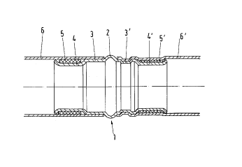
Figure 1 A longitudinal section through a first embodiment of the pipe connectoraccording to the invention;
l:iigure 2 Like ~igure 1, but a different embodiment.

Figure 1 shows, in longitudinal section, a first embodiment of the pipe connector according
to the invention. The left part of the drawing shows the pipe connector in the slipped-on
state. The right part of the drawing shows the pipe connector after pressing. The core of the
connection is a fitting 1,

CA 02232417 1998-03-18

which has a StOp 2 embodied as a bulge that extends radially outward. Attached thereto, at
least toward one side, is a cylindrical section 3, 3' that extends in the longitudinal direction
and then goes over into a section having, for ~example, a flat recess 4, 4'. Arran3~ed in this
recess 4, 4' is a sealing ring j, 5'. In this example, two smooth-ended conduit pipes 6, 6' are
slipped onto the fitting 1, specifically, up to the stop 2. By means of a pressing tool (not
shown here~, the two pressing points are deforrned one after the other. As mentioned above,
the right part of the dra~ing shows the pressed state. The deformed section 3' thereby
undertakes the axial locking of the pipe connector, while the section 4' performs the sealing
function. In section 3', both the slipped-on pipe 6' and the fitting section 3' located below
the pipe 6' are de~ormed. The type of pressing-in, e.g., hexagonal or lemon-shaped segmen~s,
depends on the contour of the mouth of the pressing jaws (not shown here).

Figure 2 shows a second embodiment, which uses the same reference numbers as in Figure 1
for the same parts. Again, the left part of the drawing shows the pipe connector in the
slipped-on state, while the right part of the drawing shows the pressed state. The fitting 1,
in geometry and shape, is the same as in Figure 1. The pipe end sections are designed
differently. The smooth-ended pipes 7, 7' have an expanded section 8, 8' in the sli~on region
on the fitting 1. The section 8, 8' is selected in such a way that the internal diameter 9, 9' of
the actual conduit pipe 7, 7' corresponds roughly to the intér~al diameter 10, 10' of the fitting
1 in the sealing region. Thus, pressure losses are largely avoided in the connection region.
Representative Drawing
A single figure which represents the drawing illustrating the invention.
Administrative Status

For a clearer understanding of the status of the application/patent presented on this page, the site Disclaimer , as well as the definitions for Patent , Administrative Status , Maintenance Fee  and Payment History  should be consulted.

Administrative Status

Title Date
Forecasted Issue Date Unavailable
(86) PCT Filing Date 1996-09-09
(87) PCT Publication Date 1997-04-10
(85) National Entry 1998-03-18
Dead Application 2003-09-09

Abandonment History

Abandonment Date Reason Reinstatement Date
2002-09-09 FAILURE TO PAY APPLICATION MAINTENANCE FEE

Payment History

Fee Type Anniversary Year Due Date Amount Paid Paid Date
Registration of a document - section 124 $100.00 1998-03-18
Application Fee $300.00 1998-03-18
Maintenance Fee - Application - New Act 2 1998-09-09 $100.00 1998-08-17
Maintenance Fee - Application - New Act 3 1999-09-09 $100.00 1999-08-16
Maintenance Fee - Application - New Act 4 2000-09-11 $100.00 2000-08-16
Maintenance Fee - Application - New Act 5 2001-09-10 $150.00 2001-08-16
Owners on Record

Note: Records showing the ownership history in alphabetical order.

Current Owners on Record
MANNESMANN AKTIENGESELLSCHAFT
Past Owners on Record
DIEDERICHS, ROLF
Past Owners that do not appear in the "Owners on Record" listing will appear in other documentation within the application.
Documents

To view selected files, please enter reCAPTCHA code :


To view images, click a link in the Document Description column. To download the documents, select one or more checkboxes in the first column and then click the "Download Selected in PDF format (Zip Archive)" or the "Download Selected as Single PDF" button.

List of published and non-published patent-specific documents on the CPD .

If you have any difficulty accessing content, you can call the Client Service Centre at 1-866-997-1936 or send them an e-mail at CIPO Client Service Centre.


Document
Description 
Date
(yyyy-mm-dd) 
Number of pages   Size of Image (KB) 
Representative Drawing 1998-07-08 1 5
Drawings 1998-03-18 1 21
Cover Page 1998-07-08 1 49
Abstract 1998-03-18 1 22
Description 1998-03-18 3 137
Claims 1998-03-18 2 68
PCT 1998-03-18 17 540
Assignment 1998-03-18 4 168
PCT 1998-03-19 7 169