Language selection

Search

Patent 2232566 Summary

Third-party information liability

Some of the information on this Web page has been provided by external sources. The Government of Canada is not responsible for the accuracy, reliability or currency of the information supplied by external sources. Users wishing to rely upon this information should consult directly with the source of the information. Content provided by external sources is not subject to official languages, privacy and accessibility requirements.

Claims and Abstract availability

Any discrepancies in the text and image of the Claims and Abstract are due to differing posting times. Text of the Claims and Abstract are posted:

  • At the time the application is open to public inspection;
  • At the time of issue of the patent (grant).
(12) Patent: (11) CA 2232566
(54) English Title: METHOD FOR MAKING CONTACT WITH A MULTIPOLE FEMALE STRIP CONNECTOR
(54) French Title: PROCEDE DE MISE EN CONTACT D'UN CONNECTEUR A BANDE DE RACCORD FEMELLE
Status: Deemed expired
Bibliographic Data
(51) International Patent Classification (IPC):
  • H01R 13/187 (2006.01)
  • H01R 4/24 (2006.01)
  • H01R 4/26 (2006.01)
  • H01R 9/053 (2006.01)
(72) Inventors :
  • ZELL, KARL (Germany)
  • SEIBOLD, JURGEN (Germany)
  • SEIDEL, PETER (Germany)
(73) Owners :
  • SIEMENS AKTIENGESELLSCHAFT (Germany)
(71) Applicants :
  • SIEMENS AKTIENGESELLSCHAFT (Germany)
(74) Agent: FETHERSTONHAUGH & CO.
(74) Associate agent:
(45) Issued: 2002-08-20
(86) PCT Filing Date: 1996-09-10
(87) Open to Public Inspection: 1997-03-27
Examination requested: 1998-03-19
Availability of licence: N/A
(25) Language of filing: English

Patent Cooperation Treaty (PCT): Yes
(86) PCT Filing Number: PCT/DE1996/001700
(87) International Publication Number: WO1997/011512
(85) National Entry: 1998-03-19

(30) Application Priority Data:
Application No. Country/Territory Date
195 35 108.8 Germany 1995-09-21

Abstracts

English Abstract


Method for making contact with a multipole female strip
connector
The present invention relates to a method for making
contact with a multipole female strip connector for plug
connections with coaxial connecting cables.
In order to simplify the method and to save
tools, a multi-row female strip connector is split into
plastic disks, one side of the disk having insulation-
piercing terminals which are arranged one behind the
other and are connected to contact springs, and the other
side having correspondingly formed, overmolded pressure
pieces. The disks are held spaced apart in a pressing
tool by means of corresponding press-in pins which have
a force fit. Coaxial connecting cables, which are cut to
length and at whose free ends the outer insulation and
the shield mesh have been removed over a predetermined
length, are pushed into these disks, which are
preassembled spaced apart. When the disks are pressed
together, the pressure pieces press the connecting wires
into the insulation-piercing terminal.


French Abstract

La présente invention concerne un procédé permettant de mettre en contact un connecteur multipolaire à ressort destiné à la réalisation de connections par fiches avec des câbles de raccordement coaxiaux. Pour que le procédé soit simplifié et que le nombre d'outils soit limité, un connecteur à ressort à plusieurs rangées est divisé en disques de plastique, un côté de chaque disque présentant des éléments autodénudants placés l'un derrière l'autre et reliés à des ressorts de contact, et l'autre côté présentant des éléments de pression moulés par injection de façon à avoir une forme correspondante. Les disques sont espacés par des broches correspondantes insérées à ajustage serré. Des câbles de connexion coaxiaux coupés à la longueur désirée sont insérés dans ces disques prémontés et espacés, une longueur prédéfinie de l'isolation extérieure et de la tresse de blindage ayant été enlevée aux extrémités libres desdits câbles. Lorsque les disques sont pressés les uns contre les autres, les fils de connexion sont pressés contre l'élément autodénudant par les éléments de pression.

Claims

Note: Claims are shown in the official language in which they were submitted.


-6-

Claims

1. A method for making contact with a multipole
female strip connector for plug connections with coaxial
connecting cables,
characterized in that
the female strip connector (1) is composed of a plurality
of plastic disks (2, 3, 4) which are designed in such a
manner that at least a first of their sides is designed
to accommodate insulation-piercing terminals (6) and
contact springs (7) which are integrally connected to
them,
in each case one insulation-piercing terminal (6) for the
inner conductor and one insulation-piercing terminal (7)
for the shield mesh, which are arranged aligned one
behind the other, being provided per coaxial connecting
cable,
the insulation-piercing terminals (6) for the inner
conductors and the associated contact springs (8) being
arranged aligned one behind the other, and
the insulation-piercing terminals (7) for the shield mesh
being connected via a cross-connection to shield contact
springs (9) which are arranged alongside the contact
springs (8) for the inner conductors,
in that at least the other side has correspondingly
formed overmolded pressure pieces (10 - 13) which are
used to press the inner conductors and the shield meshes
into the respective insulation-piercing terminals (6, 7),
in that, of two opposite sides, one side has receptacles
for pressing pins (14) which are fitted on the other
side,
in that the plastic disks (2, 3, 4) which are
preassembled with the insulation-piercing terminals (6,
7) and contact springs (8, 9) are held spaced apart
within a pressing tool by the pressing pins (14), which
are designed to be a force fit,
in that coaxial connecting wires (5), which are cut to
length and


-7-

have free inner conductors at their ends, are pushed into
these plastic disks (2, 3, 4), which are preassembled
spaced apart, in the insertion direction of the female
strip connector (1), and
in that the plastic disks (2, 3, 4) are pressed together
by means of the pressing tool.
2. A plastic disk for carrying out the method as
claimed in claim 1,
characterized
in that the pressure pieces (10 - 13) are respectively
arranged both inside the insulation-piercing terminal
regions of the insulation-piercing terminals (6, 7) and
outside the insulation-piercing terminal regions of the
insulation-piercing terminals (6, 7).
3. The plastic disk as claimed in claim 2 for
carrying out the method as claimed in claim 1,
characterized
in that the pressure pieces (12, 13) outside the
insulation-piercing terminal regions of the insulation-
piercing terminals (6, 7) enclose virtually half the
insulated inner conductor or the connecting cable (5).
4. The plastic disk as claimed in claim 2 for
carrying out the method as claimed in claim 1,
characterized
in that the pressure surface of the pressure pieces (10,
11) which are located inside the insulation-piercing
terminal regions of the insulation-piercing terminals (6,
7) are formed by a slight trough-shaped depression in the
pressure pieces (10, 11).

Description

Note: Descriptions are shown in the official language in which they were submitted.


CA 02232566 1998-03-19
FILE, P~IN-fN THIS t-
T.~H' TRANSLATIU~~
Description
Method for making contact, with a multipole female strip
connector
The present invention re=lates to a method for making
contact with a multipole female strip connector for plug
connections with coaxial connecting cables.
In the case of they known female strip connectors,
l0 special coaxial connectors, which occupy a relatively
large amount of space, ar~? snapped in when high connect
ive quality is required. .A further disadvantage of these
connectors is that they interfere with the standard
connector geometry. In the case of less stringent quality
requirements, the inner conductor was provided with a
normal crimped spring, and the shield was clamped on the
metallic housing. If it is intended to shield coaxial
junctions using an intermediate grid size, the shield is
separated out, twisted to form a conductor, and likewise
has a crimped spring atta~~hed. All the methods mentioned
here are complex and expensive and demand complex special
tools or manual activities.
The object of the present invention is to specify
a method for making contact with a multipole female strip
connector for plug connections with coaxial connecting
wires, which method can b.=_ carried out easily and is not
as complex as the known methods.
For a method of the type mentioned above, this
object is achieved as claimed in the invention by the
female strip connector being composed of a plurality of
plastic disks which are designed in such a manner that at
least a first of their sides is designed to accommodate
insulation-piercing terminals and contact springs which
are integrally connected to them,
in each case one insulat=ion-piercing terminal for the
inner conductor and one insulation-piercing terminal for
the shield mesh, which a=re arranged aligned one behind
the other, being provided per coaxial connecting cable

CA 02232566 1998-03-19
- 2 -
the insulation-piercing terminals for the inner conduc-
tors and the associated contact springs being arranged
aligned one behind the other, and
the insulation-piercing terminals for the shield mesh
being connected via a cross-connection to shield contact
springs which are arranged alongside the contact springs
for the inner conductors,
in that at least the ot=her side has correspondingly
formed overmolded pressure pieces which are used to press
the inner conductors and the shield meshes into the
respective insulation-piercing terminals,
in that, of two opposite sides, one side has receptacles
for pressing pins which are fitted on the other side,
in that the plastic diskswhich are preassembled with the
insulation-piercing terminals and contact springs are
held spaced apart within a pressing tool by the pressing
pins, which are designed t:o be a force fit,
in that coaxial connecting wires, which are cut to length
and have free inner conductors at their ends, are pushed
into these plastic disks, which are preassembled spaced
apart, in the insertion direction of the female strip
connector, and
in that the plastic disks are pressed together by means
of the pressing tool.
The method as claimed in the invention has the
advantage that it can be carried out easily, since there
is no need to use special connectors, or special, complex
method steps.
Advantageous refinements of the method as claimed
in the invention result from the dependent claims and
from the following descr_'~ption of a female strip con
nector which is illustrated in the drawing and in which
the method as claimed in t:he invention is used.
In the drawing,
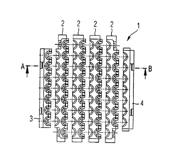
FIG 1 shows a plan view of a fitted female strip con-
nector, in which the method as claimed in the
invention is

CA 02232566 1998-03-19
- 3 -
used, before the :plastic disks have been pressed
together.
FIG 2 shows a cross section A-B through FIG 1,
FIG 3 shows a cross section through FIG 1, in which the
pressing pins can be seen,
FIG 4 shows a longitudinal section through a female
strip connector in which the method as claimed in
the invention is used,
FIG 5 shows various arrangements of the insulation
piercing terminals and contact springs for the
shield mesh,
FIG 6 shows a wiring example for the contact springs in
the female strip connector, and
FIG 7 shows a cross sE:ction through a female strip
connector in which the method as claimed in the
invention is used, after the plastic disks have
been pressed together.
The female strip connector 1 in which the method
as claimed in the invention is used comprises the plastic
disks 2, 3, 4, the plastic disks 2 being inner plastic
disks which are all designed identically. The plastic
disks 3 and 4 are outer :plastic disks 4. These plastic
disks each have a smooth surface on one of their sides,
which smooth surfaces at the same time form outer sur-
faces of the female strip connector 1.
The plastic disks 2 are designed on one side in
such a manner that they accommodate the insulation-
piercing terminals 6 and '7 and the contact springs 8 and
9 which are connected to them. In this case, the
insulation-piercing terminals 6 are used for connection
of the inner conductors o:E the coaxial connecting cables
5 to be connected, and are in each case connected to the
contact springs 8. The insulation-piercing terminals 7
are used for connection of: the shield mesh of the coaxial
connecting cable, and are in each case connected to the
contact springs 9. As can

CA 02232566 1998-03-19
- 4 -
be seen from FIG 5, in order to connect the coaxial
connecting cable, it is only necessary to remove the
outer insulation and the shield mesh at the free end of
the cable that is to be connected.
Overmolded pressu_~e pieces 10 to 13 are fitted on
the other side of the plastic disks 2. Of these pressure
pieces, the pressure pieces 10 and 11 are located inside
the insulation-piercing terminal regions of the insula-
tion-piercing terminals 6 and 7, while the pressure
pieces 12 and 13 are respectively located on the two
sides, outside the insulation-piercing terminal regions
of the insulation-piercing terminals 6 and 7.
The pressure pieces 12 and 13 which are arranged
outside the terminal regions are designed in such a
manner that they enclose virtually 180° of the connecting
cables 5 and their insulated inner conductors and in this
way form a guide for insertion of the connecting wires 5
(which has been prepared as described above) into the
preassembled and spaced--apart plastic disks 2, and
furthermore prevent the ~~onnections 5 from being bent
while they are being pre:~sed together. In consequence,
the pressure surface of t:he pressures pieces 10 and 11
which are located inside the insulation-piercing terminal
regions of the insulation-piercing terminals 6 and 7 is
formed by a slight trough--shaped depression for applying
high pressure while they <~re being pressed together.
Furthermore, one .side of the plastic disks 2 is
in each case provided with pressing pins 14 which engage
in receptacles (not shown) on the opposite side. The
pressing pins 14 have a force fit. In the case of the
illustrated female strip connector 1, the pressing pins
14 are located on that side of the plastic disks 2 on
which the pressure pieces 10 to 13 are located.
The statements made above apply in a correspon-
ding manner to the outer plastic disks 3 and 4.

CA 02232566 1998-03-19
- 5 -
The actual contact-making process will now be described.
First of all, the individual plastic disks 2 are
fitted with the insulation-piercing terminals 6 and 7 and
the contact springs 8 and 9, the insulation-piercing ter
urinals 6 and the contact springs 8 as well as the
insulation-piercing terminals 7 and the contact springs
9 in each case forming a unit. The plastic disks 2, 3 and
4 are then placed against one another. Since the pressing
pins 14 have a force fit, the plastic disks are kept at
a predetermined distance from one another as long as no
real pressure is exerted by the pressing tool.
The connecting cables 5, which have been cut to
length and have been prepared as described above, are
then ir~serted from above, between these plastic disks 2,
3 , 4 (which have been preassembled and are held spaced
apart) in the insertion direction of the female strip
connector 1. Once the connecting cables 5 have been
inserted, the plastic disks are pressed together by means
of a simple pressing tool.. This completes the contact
making process.
In the case of t:he method as claimed in the
invention, the pressure pieces 10 to 13 take over the
function of the contact-making tool which is required in
addition for the known contact-making method. In addi-
tion, there is no need fo:r additional use of a crimping
tool in the case of the method as claimed in the inven-
tion.
As can be seen in Figures 4 to 6, the configur-
ation of the connection between the insulation-piercing
terminals 7 for the shield mesh of the connecting cable
5 and the contact springs 9 which are conductively
connected to them can be: designed differently, FIG 6
illustrating just one exemplary solution. The configur-
ation may be designed such that in each case one or more
contact springs 8 which carry the actual signal are
surrounded by contact springs 9 which carry the shield
potential.

Representative Drawing
A single figure which represents the drawing illustrating the invention.
Administrative Status

For a clearer understanding of the status of the application/patent presented on this page, the site Disclaimer , as well as the definitions for Patent , Administrative Status , Maintenance Fee  and Payment History  should be consulted.

Administrative Status

Title Date
Forecasted Issue Date 2002-08-20
(86) PCT Filing Date 1996-09-10
(87) PCT Publication Date 1997-03-27
(85) National Entry 1998-03-19
Examination Requested 1998-03-19
(45) Issued 2002-08-20
Deemed Expired 2004-09-10

Abandonment History

There is no abandonment history.

Payment History

Fee Type Anniversary Year Due Date Amount Paid Paid Date
Request for Examination $400.00 1998-03-19
Registration of a document - section 124 $100.00 1998-03-19
Application Fee $300.00 1998-03-19
Maintenance Fee - Application - New Act 2 1998-09-10 $100.00 1998-08-17
Maintenance Fee - Application - New Act 3 1999-09-10 $100.00 1999-08-12
Maintenance Fee - Application - New Act 4 2000-09-11 $100.00 2000-08-18
Maintenance Fee - Application - New Act 5 2001-09-10 $150.00 2001-08-16
Final Fee $300.00 2002-06-06
Maintenance Fee - Patent - New Act 6 2002-09-10 $150.00 2002-08-16
Owners on Record

Note: Records showing the ownership history in alphabetical order.

Current Owners on Record
SIEMENS AKTIENGESELLSCHAFT
Past Owners on Record
SEIBOLD, JURGEN
SEIDEL, PETER
ZELL, KARL
Past Owners that do not appear in the "Owners on Record" listing will appear in other documentation within the application.
Documents

To view selected files, please enter reCAPTCHA code :


To view images, click a link in the Document Description column. To download the documents, select one or more checkboxes in the first column and then click the "Download Selected in PDF format (Zip Archive)" or the "Download Selected as Single PDF" button.

List of published and non-published patent-specific documents on the CPD .

If you have any difficulty accessing content, you can call the Client Service Centre at 1-866-997-1936 or send them an e-mail at CIPO Client Service Centre.


Document
Description 
Date
(yyyy-mm-dd) 
Number of pages   Size of Image (KB) 
Cover Page 1998-06-18 2 76
Abstract 1998-03-19 1 27
Description 1998-03-19 5 225
Claims 1998-03-19 2 75
Drawings 1998-03-19 4 136
Abstract 2002-07-17 1 27
Cover Page 2002-08-06 1 53
Representative Drawing 1998-06-18 1 16
Representative Drawing 2002-08-06 1 17
Correspondence 2002-06-06 1 43
PCT 1998-03-19 15 530
Assignment 1998-03-19 3 129
PCT 1998-05-28 6 179
Correspondence 2002-06-13 1 35
Prosecution-Amendment 2002-05-31 1 46