Note: Descriptions are shown in the official language in which they were submitted.
CA 022328~6 1998-03-24
W O 97/12170 PCTAUS95/12282
OUICR CONNECTOR WITH CONFIRNATION FEATURE
R~CR~POUND OF THE lN V ~. lON
This invention relates generally to a conduit coupling
through which fluid flows. More particularly, the present
invention relates to a quick connector which retains a male
conduit within a female receptacle, and a connection of
this type which includes a ring for confirming proper
connection.
In the automotive industry (as well as for many other
industries) the need always exists for low cost, reliable,
and easy-to-assemble components. This need is especially
apparent with respect to providing a connection between
fluid conveying conduits, such as fuel, brake, or
refrigerant lines. Traditionally, such a connection is
comprised of a male conduit being retained within a female
receptacle through use of threaded fittings, flare
fittings, or through bolted-on flanges.
More recently, a variety of snap together quick
connect retainers have been used in place of the
conventional methods. These quick connectors typically
have a plurality of flexible legs which engage an annular
bead attached to a male conduit and also engage an undercut
groove formed within a female member. Two such examples
are disclosed in U.S. Patent No. 4,601,497 entitled
"Swivelable Quick Connector Assembly" which issued on July
22, 1986, and U.S. Patent No. 4,778,203 entitled
CA 022328~6 1998-03-24
W O 97/12170 PCT~US95/12282
"Swivelable Quick Connector for High Temperature
Connection" which issued on October 18, 1988, both of which
were invented by the inventor of the present invention and
are incorporated by reference herewithin. Another quick
connector has a retainer which is flat with pairs of
annular arms extending therearound which are radially
flexible. Other quick connectors which were invented by
the inventor of the present invention are disclosed in U.S.
Patent Nos. 4,524,995 and 4,423,892, both of which are
entitled "Swivelable Quick Connector Assembly" and which
issued on June 25, 1985, and January 23, 1984,
respectively, and are incorporated by reference herewithin.
While the aforementioned quick connectors present
significant improvements in the art, it is desirable to
advance the improvements of the known art. Specifically,
it is desirable to provide a coupling retainer which
readily fits into the female receptacle and is easily
removed therefrom. It is also desirable to provide a
coupling retainer with a minimum number of parts and is
shallow enough to be used instead of a screw-in type joint.
In addition, it is desirable to provide such a coupling
which clearly indicates that the quick connector-male
conduit assembly is properly seated within the female
receptacle.
CA 022328~6 1998-03-24
W O 97/12170 PCT~US95/12282
8UN~G~RY OF THE PRESENT lNV~N~lON
In accordance with the present invention, a preferred
embodiment of the coupler includes an array of three, or
~ with the indicator, four quick connector engagement
components fitted to the end of a male conduit to form a
quick connector-male conduit assembly in addition to the
parts required for sealing. The array includes an
intermediate plate, a retainer, a backing plate, and, as a
forth component, a seating indicator. The intermediate
plate includes a pair of alignment nibs that align the
plate with the adjacent retainer, which itself includes a
pair of release and alignment tabs for alignment with the
backing plate for use when a metal tube or a plastic tube
and tube liner are used. The backing plate also includes
a tab which is used for aligning the backing plate with the
seating indicator and the retainer. The array of these
engagement components is substantially self-centering on
the male conduit. Because of the series of alignment
members, the engagement components also resist rotation
with respect to each other.
The retainer includes a ring which fits about a
portion of the male conduit and a pair of outer arms on
which the release (and alignment to the intermediate plate
and the seating indicator) tabs are formed. The ring and
the outer arms lie substantially within a common plane. A
locking lug is formed along the outer periphery of each of
the outer arms for releasable engagement with a locking
CA 022328~6 1998-03-24
W O 97/12170 PCTAUS95/12282
recessed bore formed along the inner circumference of the
axial bore of the female receptacle. The outer arms are
coaxial with the ring. The ring and the outer arms are
attached to each other at a common area which allows the
outer arms to be moved toward one another such as by
squeezing, independent of the inner arms. A series of
bushings and an 0-ring (or 0-rings) are provided adjacent
the array of engagement components to provide for proper
seal of the male conduit within the female receptacle, as
well as providing for proper fit of these components with
respect to each other, such that a bearing on the male
portion to the female portion, on each side (inner and
outer) of the sealing member is provided.
Insertion of the quick connector-male conduit assembly
is effected by the installer generally positioning the free
end of the male conduit into the female receptacle and (if
a seating indicator is used) pushing against a pop-off ring
until the ring franges from the body of the seating
indicator. The franging action indicates that the quick
connector-male conduit assembly is properly seated within
the female receptacle. The outer arms of the retainer and
their associated locking lugs are squeezed toward the inner
arms as the retainer is forced past a concave outer surface
formed on the female receptacle.
Removal of the assembly from the female receptacle is
easily accomplished by the remover squeezing the release
and alignment tabs toward one another either by use of a
CA 022328~6 1998-03-24
W O 97/12170 PCT~US95/12282
hand or a tool so as to force the outer arms toward the
inner arms, thus allowing the locking lugs to clear the
radial retainer-locking wall forming the locking recessed
bore in the bore of the female receptacle. Once cleared,
the remover withdraws the quick connector-male conduit
assembly from the female receptacle. The quick connector
male is an assembly that is placed directly on the conduit
that carries the fluid.
The present invention overcomes some of the
difficulties associated with assembly and disassembly of
known connectors. Specifically, the retainer does not
require assembly to a centering component other than the
conduit. Furthermore, the springing interlocking part is
like a snap-ring and is in the plane of the locking to the
female portions, thus eliminating known springs that
undesirably occupy some length parallel to the conduit and
are at right angles to the plane of the radial retainer-
locking wall of the locking recessed bore and the locking
portions carried on the conduit by the springing component.
Accordingly, it is an object of the present invention
to provide a hand-releasable quick connector that
incorporates a relatively thin retainer.
It is a further object of the present invention to
provide a connection that can employ both metal and plastic
for the male and female portions.
CA 022328~6 1998-03-24
W O 97/12170 PCT~US95/12282
It is yet still another object of the present
invention to provide several variations male and female
components of the connection.
It is a further object of the present invention to
provide such a retainer that is relatively inexpensive to
manufacture.
A further object of the present invention is to
provide a swivelable quick connector which can be used to
replace, in the same space, a flare or screw-in connector.
Still another object of the present invention is to
provide a self-centering snap ring-type of retainer that
may be released by hand.
A further object of the present invention is to
provide a quick connector which can be a part of the
conduit between connections.
Still another object of the present invention is to
provide a quick connector which has a pop-off ring to show
when a connection is properly made.
Additional advantages and features of the present
invention will become apparent from the following
description and appended claims, taken in conjunction with
the accompanying drawings.
BRIEF DESCRIPTION OF THE DRAWINGS
The above-noted advantages as well as other advantages
of the present invention will become apparent to one
skilled in the art by reading the following specification
CA 022328~6 1998-03-24
W O 97/12170 PCT~US95/12282
and subjoined claims in conjunction with reference to the
following drawings in which:
Figure l shows an exploded view of the quick connector
according to a preferred embodiment of the present
invention;
Figure 2 is a sectional view of the quick connector-
male conduit elements of Figure 1 assembled and spaced
apart from a female receptacle, also shown in section;
Figure 3 is a sectional view of a quick connector-male
conduit assembly like Figures 1 and 2 locked in position
within an alternate embodiment of a female receptacle;
Figure 4 is a perspective view of one side of the
quick connector intermediate plate according to a preferred
embodiment of the present invention;
Figure 5 is an end view of the quick connector
intermediate plate shown in Figure 4;
Figure 6 is a perspective view of side opposite that
side of the quick connector intermediate plate shown in
Figure 4;
Figure 7 is a perspective view of the retainer of the
assembly according to a preferred embodiment of the present
invention;
Figure 8 is an end view of the retainer of Figure 7;
Figure 9 is a sectional view of the retainer according
to a preferred embodiment taken along lines 9-9 of Figure
8;
CA 022328~6 1998-03-24
W O 97/12170 PCT~US95/12282
Figure lO is a sectional view taken along lines 10-lO
of Figure 8;
Figure ll is a sectional view taken along lines 11-11
of Figure 8;
Figure 12 is a sectional view taken along lines 12-12
of Figure ll;
Figure 13 is a perspective view of the backing plate
according to a preferred embodiment of the assembly of the
present invention;
Figure 14 is a side view of the backing plate of
Figure 13;
Figure 15 is an end view of the backing plate of
Figure 13, taken from the side opposite that shown in
Figure 13;
Figure 16 is a perspective view of the intermediate
plate and the retainer ring according to a preferred
embodiment of the present invention;
Figure 17 is a perspective view of the array of
seating indicator, backing plate, retainer, and
intermediate plate components according to a preferred
embodiment of the present invention;
Figure 18 is a perspective view of the seating
indicator of Figure 17;
Figure l9 is an end view of the seating indicator of
Figure 18;
Figure 20 is side view of the seating indicator of
Figure 18;
CA 022328~6 1998-03-24
W O 97/12170 PCT~US95/12282
Figure 21 is a partial, detailed sectional view of the
quick connector-male conduit assembly having been locked
into place with the pop-off ring of the seating indicator
in its franged position;
Figure 22 is a view similar to the view of Figure 21
but illustrating the ring element in spaced apart relation
from the female receptacle;
Figure 23 is a sectional view illustrating an
alternate embodiment of the quick connector-male conduit
assembly of the present in spaced apart relation from the
female receptacle of Figure 3;
Figure 24 is a sectional view of an embodiment of the
quick connector-male conduit assembly of Figure 24 locked
in place within still a further alternate embodiment of the
female receptacle according to the present invention; and
Figure 25 is a perspective view of an alternate
embodiment of the retainer fitted to the intermediate plate
according to a preferred embodiment of the present
invention.
DETAILED DE8CRIPTIONS OF THE PREFERRED EMBODIMENT8
In general, the present invention is directed to a
quick connector-male conduit assembly incorporating a hand-
releasable, self-centering ring-like retainer having a
seating indicator assembled therewith. The seating
indicator includes a pop-off ring to assist in the
installation of the quick connector-male conduit assembly
CA 022328~6 1998-03-24
W O 97/12170 PCTAJS95/12282
into a female receptacle and to positively indicate to the
installer that a male conduit has been locked to a female
receptacle. The present invention finds utility in, for
example, coupling the tubing disposed between the elements
of fuel, water, or oil systems. It may be used with
plastic or metal conduits, as shown in the inventor's
pending United States patent application Serial No.
08/503,454, titled MEANS OF COUPLING NON-THREADED
CONNECTIONS.
More particularly, the connector of the present
invention also finds application in external oil lines and
hoses as well as in hydraulic brake systems. The present
connector may also be used in vehicle fuel systems,
between, for example, the fuel tank and the fuel pump and
the carburetor or fuel injection system. While having
particular usefulness in motor vehicles, the connector of
the present invention may also find application in
virtually any situation in which male and female fluid-
carrying lines must be connected.
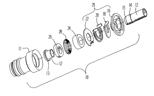
Referring to Figure l, an exploded view of a quick
connector-male conduit assembly, collectively referred to
as l0, and an exemplary female receptacle ll is
illustrated. The female receptacle ll as illustrated is of
the deep drawn type and may be made of a drawn metal or
other material. The assembly l0 includes a male conduit
12 (shown broken). The male conduit 12 is an elongated
cylindrically-shaped part having a distal portion or
CA 022328~6 1998-03-24
W O 97/12170 PCTrUS95/12282
flanged end 13 and a raised collar 14 formed at a
predetermined longitudinal distance from the flanged end
13. The raised collar 14 includes a radial wall 15. The
- assembly 10 acts as a fluid conduit for a fuel, braking or
refrigeration system within an automotive vehicle or the
like. Therefore, the male conduit 12 must be securely
affixed within the female receptacle 11.
The assembly 10 also includes a seating indicator 16,
a backing plate 18, a hand-releasable, self-centering
retainer 20, an intermediate plate 22, a pair of bushings
24 and 26, and an 0-ring 28. (It is to be understood that
the O-ring 28 is provided for sealing and could consist of,
for example, a pair of 0-rings.) The seating indicator 16,
the backing plate 18, the retainer 20, and the intermediate
plate 22 collectively form an array of engagement
components 29. The bushings 24 and 26 are annular shaped
and are preferably defined by quadrilateral walls having
rectangular cross sectional shapes. However, as is known
to one skilled in the art, such bushings may be U-shaped.
The bushings 24 and 26 are useful in "piloting" the
assembly 10 into the female receptacle 11. The bushings 24
and 26 are made from a plastic material or a metallic
material having sufficient hoop strength to withstand the
radially outward-directed forces acting thereupon, or they
can be slip-fitted along the conduit from plastic or metal.
The 0-ring 28 is preferably formed from an elastomeric
material such as rubber.
1 1
CA 022328~6 1998-03-24
W O 97/12170 PCT~US95/12282
The bushing 26 and the O-ring 28 are both sealing and
supporting members, and their configuration and even their
numbers could be altered as necessary to provide for proper
fluid-tight assembly of the male and female components.
The engagement components of the array 29, the bushings 24
and 26, and the O-ring 28 are captured between the flanged
end 13 and the radial wall 15 of the raised collar 14. An
exterior side of the bushing 24 engages the plate 22
thereby transferring the forces that would otherwise
separate the male conduit 12 from the female receptacle ll.
The plate 22 acts to receive these separation forces on the
male conduit 12 from the bushing 24 and transfer the forces
to the female receptacle ll by interlocking with a radial
retainer-locking wall forming one wall of a recessed bore
formed in the female receptacle 11, as will be described
below. The wall 15 keeps the engagement component array 29
from translating away from the connection.
Figure 2 is a modified view of the exploded view shown
in Figure 1 showing the components of the quick connector-
male conduit assembly 10 assembled on the end of the maleconduit 12. The general configuration of the male conduit
12 and its overall design are some of the subjects of the
inventor's pending United States patent application, Serial
No. 08/503,454, titled MEANS OF COUPLING NON-THREADED
CONNECTIONS. As is known in the art, part of the end of
the female receptacle ll is fitted within the end of a hose
or line 30 which is preferably made from a semi-flexible
12
_
CA 022328~6 1998-03-24
W O 97/12170 ' PCT~US95/12282
and expandable elastomeric material such as rubber,
however, expandable polymeric and metallic materials can
also be used.
- Figure 2 also illustrates the construction of the
female receptacle 11 which is an exemplary but not an
exclusive receptacle for use with the quick connector-male
conduit assembly 10 of the present invention. The female
receptacle includes a throughbore 31 that includes lead-in
chamfer 32 formed at the open end of the throughbore 31 of
the female receptacle 11. The chamfer 32 aids in the
installation of the retainer 20. The retainer 20 is a
quick connect fastener that includes outer flexible arms
(discussed below with respect to Figures 7 through 12) that
are compressibly squeezed inward toward the longitudinal
axis of the male conduit 12 by insertion into the lead-in
chamfer 32 of the female receptacle 11.
The throughbore 31 of the female receptacle 11 also
includes a locking recessed bore 33 adjacent the lead-in
chamfer 32. The retainer 20 is releasably locked within
the recessed bore 33. The semi-flexible hose or tube 30 is
attached to the female receptacle 11.
Referring to Figure 3, a sectional view of the
assembly 10 locked within a female receptacle 34 formed at
the end of a rigid fluid line 35 is illustrated. The
receptacle 34 includes a throughbore 36 having a lead-in
chamfer 37, a recessed bore 38, a radial retainer-locking
wall 39, an inner conical surface 44, and an inner tubular
13
CA 022328~6 1998-03-24
W O 97/12170 PCTAUS95/12282
bore 46. (The interior configuration of the female
receptacle 34 is more clearly seen in the cross-sectional
illustration of this element shown and discussed below with
respect to Figure 23.) As with the lead-in chamfer 32
discussed above with respect to Figure 2, the lead-in
chamfer 37 compressibly squeezes the compressible elements
of the retainer 20 to thereby allow it to pass into the
recessed bore 38 and to lock against the radial retainer-
locking wall 39. The inner conical surface 44 pilots the
10 bushing 26 (together with the O-ring 28 and the bushing 24)
into the inner tubular bore 46.
The seating indicator 16 includes a pop-off ring 48.
According to the illustration of Figure 3, a portion of the
seating indicator 16 has been inserted into the female
receptacle 34 by the operator pushing against the conduit
12. According to the illustrated view, the assembly 10 is
locked into place, but the pop-off ring 48 has not yet been
broken away. Pressing on the conduit 12 causes further
pressure against the pop-off ring 48 applied by the female
receptacle 34 end, than that applied to put the assembly 10
in the illustrated position, will cause it to break away
from the rest of the seating indicator 16, thus indicating
to the installer that the assembly 10 has been locked into
place in the female receptacle 34 (or any other embodiment
of the female conduit illustrated herein).
Figures 4 through 6 illustrate various views of the
plate 22. The plate 22 is formed from a rigid material,
14
CA 022328~6 1998-03-24
W O 97/12170 PCT~US95/12282
such as a metal or a hard plastic. The plate 22 includes
a flat, disc-shaped body 50 having a central, male conduit-
passing aperture 52 formed therein. At one side of the
- body 50 are formed a pair of spaced-apart alignment nibs 54
which extend outward away from the plane of the body 50.
The nibs 54 have a space 56 formed therebetween, the
purpose of which will be described below with respect to
several of the following figures.
Figures 7 through 12 illustrate various whole and
sectional views of the hand-releasable, self-centering
retainer 20 of the present invention. The retainer 20
includes a ring 62 that is formed for disposition about a
portion of the male conduit 12 (not shown). The ring 62
extends more than 180 degrees about the male conduit 12 so
16 that the retainer 20 remains assembled thereto. It is
recognized that the ring 62 can also be truncated at the
top to make more room for release tabs, discussed below.
The retainer further includes a pair of outer arms 64 which
are concentric with the ring 62 and are connected to the
ring 62 by means of a common joining area 66. The outer
arms 64 are deflectable independent of the ring 62. The
ring 62 and the outer arms 64 are planar. Furthermore, the
ring 62 and the arms 64 are planar with the radial
retainer-locking wall 39 of the exemplary female receptacle
34 shown in Figure 3 (and with similar radial retainer-
locking walls of other female receptacles).
CA 022328~6 1998-03-24
W O97/12170 PCT~US95/12282
The cantilevered ends of each of the outer arms 64
each define a hand-release tab 68, shown perspectively in
Figure 7 and partially in the side views of Figures 9 and
10. Each of the outer arms 64 also includes a locking lug
70. The length of release tabs 68 is dependent on distance
"d" between inside surfaces of tabs 68 which is, in turn,
controlled by the outside diameter of arms 64. The tabs 68
are to close over the male conduit 12 (not shown) as the
retainer 20 is released. The locking lugs 70 extend from
10 the outside diameter of arms 64 by about .025 or .030
inches to engage an undercut diameter of the female
receptacle (not shown). The undercut diameter is similar
to a snap ring groove, but longer than a regular snap ring
groove. The retainer 20 is stamped and formed from
resilient steel or is formed from a plastic.
Referring particularly to Figure 9, a section taken
along lines 9-9 of Figure 8 is shown. This section is cut
through the common joining area 66 which joins the ring 62
(see Figure 1) with the outer arms 64. The locking lug 70
is shown projecting from the outer arms 64 in Figure 9, as
are the release tabs 68 (shown in side view).
Referring to Figure 10, a section taken along lines
10-10 of Figure 8 is illustrated. The area of the
illustrated section is cut through outer arm 64, joining
area 66 and the ring 62.
Referring to Figure ll, a section taken along lines
11-11 of Figure 8 is illustrated.
16
-
CA 022328~6 1998-03-24
W O 97/12170 PCT~US95/12282
Referring to Figure 12, a section taken along lines
12-12 of Figure 11 is illustrated. In order that the
locking lug 70 not scrape or gall against the chamfer lead-
- in of the female member (not shown) during quick connect
installation, the locking lug 70 is formed so as to present
a smooth surface.
Referring to Figures 13 through 15, various views of
the backing plate 18 are illustrated. Like the plate 22,
the backing plate 18 is generally formed from a flat, disc-
like plate of a rigid material such as a metal or aplastic. The plate 18 includes a body 76. A male conduit-
passing aperture 78 is centrally formed in the body 76 of
the plate 18. Unlike the plate 22, however, a tab 80 of
the plate 18 is bent substantially perpendicularly with
respect to the plane of the body 76. Adjacent the tab 80
are a pair of notches 82 which slottably receive the
release tabs 68 of the retainer 20.
The tab 80 functions to align the plate 18 with the
seating indicator 16 and the retainer 20, and to
substantially prevent rotation of these three elements with
respect to each other. The tab 80 also functions to
prevent the spring portions of arms 64 (as illustrated in
Figures 7, 8, and 9) from becoming over-stressed. A pair
of recesses 84 are also formed in the sides of the body 76
of the plate 18 to receive the locking lugs 70 of the
retainer 20.
CA 022328~6 l998-03-24
W O 97/12170 PCT~US95/12282
Figure 16 shows a portion of the array 29 with the
intermediate plate nested against the retainer 20. As will
be understood by referring to Figure 16, the nibs 54 of the
plate 22 are placeable on either side of the common joining
5 area 66, thereby capturing the retainer 20 and preventing
rotation of the plate 22 with respect to the retainer 20.
(This is for purposes of having two diameters for 52 [the
inner diameter], one diameter is for providing room for a
plastic tube [shown in Figure 23] to be expanded by a bulge
10 108 on the end of a liner 104 as the liner 104 is inserted
into the end of the plastic conduit. These two diameters
are also used on the backing plate for inner diameter 78
[illustrated in Figures 13--15].)
The nesting of the plate 22, the retainer 20, the
15 plate 18, and the seating indicator 16 is clearly
illustrated as the engagement component array 29 of Figure
17, which is a perspective view showing these members
positioned together. The centrally-formed series of like-
sized apertures through the array 29 for receiving the
20 cylindrical form of the male conduit 12 (not shown) is
plainly visible.
Figures 18 through 20 illustrate various views of the
seating indicator 16. The indicator 16 includes
essentially three elements that are frangible from one
25 another, and, accordingly, the indicator 16 is formed from
a breakable material such as a rigid plastic, although a
18
- -
CA 022328~6 1998-03-24
W O 97/12170 PCT~US95/12282
brittle metal may as well be used as required for certain
high-temperature applications.
As noted above, the indicator 16 includes the pop-off
ring 48. The ring 48 is frangibly attached by a series of
to a semi-cylindrical body 90 having a section 92 that is
thinner than the rest of the semi-cylindrical body 90. The
section 92 is formed to accommodate the tab 80 of the plate
18. The section 92 abuts a pair of adjacent flat surfaces
94. A cylindrical, male conduit-passing bore 96 is
centrally formed through the semi-cylindrical body 90.
Within the bore 96 is a restricted bore surface 98 formed
therein. The restricted bore surface 98 (best seen in
broken lines in Figure 20) forms a shoulder 100 (also best
seen in broken lines in Figure 20) with the bore 96. The
shoulder 100 provides a stop against downstream axial
movement the male conduit 12 by a bulge formed on the male
conduit 12 (or conduit 103 shown in Figure 23). This may
be understood by, for example, reference to Figures 21 and
22. This general concept is more fully discussed in the
above-mentioned pending application.
A series of frangible bridges 102 connect the ring 48
to the semi-cylindrical body 90. It is these bridges 102
that are broken by the over-travel permitted by the length
of the snap ring-type groove in the female and after proper
connection between the quick connector-male conduit
assembly 10 is fitted within a female receptacle. As will
be seen, the bridges 102 are formed from relatively thin
19
CA 022328~6 1998-03-24
W O 97/12170 PCTnUS95/12282
stock and are, accordingly, relatively weak connecting
points which will frange before either the ring 48 or the
semi-cylindrical body 90. Once broken away, the pop-off
ring 48 is free of the body 90 and may be either snipped by
the installer and removed from the conduit 12 or may be
left on the conduit 12. Because the pop-off ring 48 is in
the shape of the ring and fully encircles the conduit 12,
it is unlikely that the presence of the ring 48 will
interfere with the operation of the vehicle even if the
ring 48 were to travel down the conduit 12.
Figures 21 and 22 illustrate a portion of the mated
quick connector-male conduit assembly 10 within the female
receptacle 34. In Figure 21, the quick connector-male
conduit assembly 10 is illustrated as having been locked
into place in the female receptacle 34. In Figure 22 the
pop-off ring 48 has been pushed off by the installer
pushing on conduit 12 beyond the locked-in position until
the plate 22 stops at the inside vertical wall of the
recessed bore 38, where this wall meets the start of the
surface 44. The pop-off ring is, accordingly, shown broken
away or franged from the body 90 (shown in broken lines in
Figure 22). As noted above, after being broken away by the
end of the lead-in chamfer 37 from the semi-cylindrical
body 90, the pop-off ring 48 is free to travel away from
25 the body 90. Figure 22 illustrates how the pop-off ring 48
may be moved away from the body 90 and, hence, the female
receptacle 34 after proper connection of the quick
CA 022328~6 1998-03-24
W O 97/12170 PCT~US95/12282
connector-male conduit assembly 10 into the female
receptacle has been completed.
Figure 23 illustrates the female receptacle 34 of
Figure 3 and the engagement components of the array 29 as
previously discussed. However, the construction of the
male conduit, generally illustrated as assembly 130, is
different from the male conduit 12 discussed above. The
conduit assembly 130, which is one aspect of the invention
of the inventor's above-mentioned pending United States
10 patent application Serial No. 08/503,454, includes a
conduit 103 and a tubular sleeve 104. The conduit 103 may
be composed either of a substantially elastic material such
as a rubber or other polymerized material, while the
tubular sleeve 104 is formed from a rigid metal or plastic.
15 The tubular sleeve 104 includes a flange 106 that acts to
retain the bushing 26, the 0-ring 28, the bushing 24, and
the engagement array 29 on the conduit 103. A bulge 108 is
formed on the sleeve 104. The bulge 108 limits axial
longitudinal translation of the components of the quick
20 connector along the conduit 103. In Figure 23, the inner
bushing 26 may be replaced by forming the sleeve 104 to
have a flange 106 that includes bushing 26.
Figure 24 is a sectional view illustrating the quick
connector-male conduit assembly 10 shown in certain ones of
the several figures and discussed above locked into a
female receptacle 110 which is a machined part of a device
111 such as a brake housing or a carburetor. The female
21
CA 022328~6 1998-03-24
WO 97/12170 PCT~US95/12282
receptacle 110 includes a blind bore 112 having a
substantially perpendicular, fluid-passing passageway 114
formed therein. The blind bore 112 further includes a
bushing and O-ring-receiving bore 116, a bore 118 and a
snap ring-like groove 122 formed in the bore 118 for
lockably receiving the quick connector-male conduit
assembly 10, and a lead-in chamfer 120. The pop-off ring
48 has been separated in the figure. This arrangement is
similar to that shown and discussed above in Figures 3 and
23 with respect to the female receptacle 34. Of course,
the configuration of the device 111 may significantly vary
from that configuration shown, and, accordingly, the device
111 should be taken only as exemplary and not limiting, as
are the configurations of each of the female receptacles
shown and discussed above with respect to the various
configurations of the present invention.
Figure 25 illustrates a perspective view of an
alternate embodiment of a hand-releasable, self-centering
retainer, illustrated as 20', fitted to the plate 22. A
pair of hand-release tabs 68' are provided in lieu of the
hand-release tabs 68 of the retainer 20 illustrated above
in Figure 16 and discussed with respect thereto. The hand-
release tabs 68' are preferably but not exclusively formed
at 90 degree angles relative to the release tabs 68. By
doing this, the plate 18 no longer requires the ear 80
(illustrated in Figure 17), and is planar instead. The gap
between the hand-release tabs 68' serves the same purpose
22
_
CA 022328~6 1998-03-24
W O 97/12170 ' PCT~US95/12282
as the ear 80 on the plate 18. The release tabs 68'
project through the seating indicator 16.
Regardless of the particular embodiment, the
connectors of the present invention disclose several
advantages over the prior art including a simple method of
installing and removing a quick connector-male conduit
assembly into and from a female receptacle and for readily
verifying that the assembly is properly and fixedly
attached.
Although the figures contain the indicator 16, it is
recognized that the indicator 16 is not necessary to
provide a fluid-tight connection. If the indicator 16 is
not used, it is only necessary that the expanded area of
the conduit be moved slightly toward the end of the
conduit.
Those skilled in the art can now appreciate from the
foregoing description that the broad teachings of the
present invention can be implemented in a variety of forms.
Therefore, while this invention has been described in
connection with particular examples thereof, the true scope
of the invention should not be so limited since other
modifications will become apparent to the skilled
practitioner upon a study of the drawings, specification,
and following claims.
23