Note: Descriptions are shown in the official language in which they were submitted.
CA 02232918 1998-03-19
PC9600AALP
SELF-EXPANDING MEDICAL DEVICE FOR CENTERING
RADIOACTIVE TREATMENT SOURCES IN BODY VESSELS
FIELD OF THE INVENTION
The present invention relates generally to medical devices for positioning
radioactive treatment sources in body vessels of patients. In particular, the
present
invention is a radially compressible and self expandable device for centering
radioactive
treatment sources in body vessels.
DESCRIPTION OF THE RELATED ART
Medical devices configured for radiation treatments of stenosis (constricted
regions) in blood flow-supporting and other vessels of a patient are generally
known and
disclosed, for example, in European Patent Publication No. 0 633 041 and
German Patent
Registration No. G 91 02 312.2. In general, the devices shown in these
publications
include an elongated flexible catheter tube with a radially expandable support
structure
such as a self expandable stmt or one or two inflatable balloons on its distal
end. The
devices are percutaneously inserted into the vessel and transluminally
directed to the
treatment site. After the support structure is located adjacent to the
treatment site it is
radially expanded to generally center the catheter tube within the vessel. A
radioactive
2 0 source is then inserted into and directed through the catheter tube until
it is located at the
treatment site. Following the treatment the radioactive source is withdrawn
through the
catheter. The support structure is then radially compressed or collapsed and
the catheter
tube withdrawn.
The intensity of radiation applied to the body tissues by sources typically
used in
2 5 these treatments varies nonlinearly with the distance of the source from
the tissue (i. e., the
intensity ~ d2). To uniformly treat the tissue, it is therefore important for
the radioactive
source to be radially centered within the vessel at the treatment site. When
used to treat
linear vessel sections, the known support structures are generally capable of
centering the
radiation source to achieve a relatively uniform distribution of radiation at
the treatment
3 0 site. However, when these support structures are positioned at treatment
sites in curved
vessel sections, the catheter tube can be bent to a radius of curvature which
is different
than the curvature of the vessel section. Portions of the catheter tube, and
therefore the
CA 02232918 2001-07-23
'77553-8
radioactive source when positioned in the tube during
treatment, will therefore be closer to one side of the vessel
than the other. As a result, the dose of radiation applied to
the treatment site may not be uniform.
It is evident that there is a continuing need for
improved support structures for use in connection with
radiation treatments of stenosis. In particular, there is a
need for support structures capable of relatively accurately
centering the radioactive source at treatment sites in curved
vessel portions. The support structure should be capable of
being accurately positioned, and relatively easily inserted and
withdrawn. A device of this type which enables radiation
treatments while allowing significant perfusion (flow) of blood
through the vessel would be particularly advantageous.
SUMMARY OF THE INVENTION
The invention provides a centering catheter for
centering a radiation source in a vascular lumen, comprising:
an elongate shaft having a proximal end and a distal end; and
an expandable braid support structure connected to the distal
end of the elongate shaft for centering the radioactive source
within the vascular lumen, the braid structure defining a
plurality of constriction regions upon expansion, the braid
comprising a plurality of interwoven radio-transparent fibers.
The invention also provides a medical system for
treating a vascular site with ionizing radiation via a vascular
lumen, comprising: an elongate radiation source; and a
centering catheter for centering the radiation source in the
vascular lumen, the centering catheter including an elongate
shaft having a proximal end, a distal end and a source lumen
extending therethrough which is adapted to accommodate the
2
CA 02232918 2001-07-23
77553-8
radioactive source therein, an expandable braid support
structure connected to the distal end of the elongate shaft for
centering the radioactive source within the vascular lumen, the
braid structure defining a plurality of constriction regions
upon expansion, the braid comprising a plurality of interwoven
radio-transparent fibers.
The support structure of the device is capable of
relatively accurately centering the radiation source within a
curved portion of a body vessel during radioactive treatments
of stenosis. The support structure can be relatively easily
positioned and withdrawn from the vessel, and allows blood
perfusion during the treatments.
The support structure is an axially flexible member
preferably formed from a plurality of filaments which are
helically wound and interwoven in a braided configuration. The
support structure includes a plurality of spaced unconstricted
regions and a plurality of spaced constricted regions. The
unconstricted regions are radially compressible and self-
expandable from a positioning diameter when the device is in a
positioning state to a vessel-engaging, treatment diameter
which is greater than the positioning diameter when the device
is in a treatment state. The constricted regions are
concentric with the unconstricted regions and have a diameter
which is less than the treatment diameter of the unconstricted
regions when the device is in the treatment state. The
radioactive source is supported within the constricted regions
of the support structure when the device is in the treatment
state.
2a
CA 02232918 2001-07-23
77553-8
BRIEF DESCRIPTION OF THE DRAWINGS
Figure 1 is an illustration of a radioactive stenosis treatment device in
accordance
with the present invention in its treatment state.
Figure 2 is an illustration of the treatment device shown in Figure 1 in its
reduced-
radius positioning state.
Figure 3 is an illustration of the treatment device shown in Figure 1 in its
treatment state positioned within a body vessel.
DETAILED DESCRIPTION OF THE PREFERRED EMBODIIVViENTS
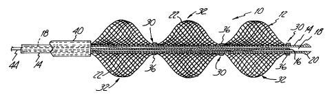
A radioactive stenosis treatment device 10 in accordance with the present
invention is illustrated in Figure 1. As shown, the distal end of device 10
includes a
support structure 12 concentrically mounted on the distal end of a tubular
catheter 14,
and a radioactive source 16 positioned within the catheter adjacent to the
support
structure. Catheter 14 is an elongated and axially flexible member having a
lumen 18 and
a tip 20 on its distal end. Catheter 18 will typically be fabricated from
polymers such as
polyethylene, PEEK (polyetheretherketones) and PTFE (polytetrafluoroethylene).
The
support structure 12 is an axially flexible member which is circular in cross
section and
formed from two sets of opposite(y-directed, parallel, spaced-apart and
helically wound
elongated strands or filaments 22. The sets of filaments 22 are interwoven in
an over and
2 0 under braided configuration intersecting at points to form an open mesh or
weave
construction. Methods for fabricating members such as support structure 12 are
generally
known and disclosed, for example, in the Wallsten U.S. Patent 4,655,771 and
the
WaILsten et al. U.S. Patent 5,061,275.
In a preferred embodiment the filaments 22 of support structure 12 are formed
TM
2 5 from relatively radiotransparent polymers such as Kevlar aramid fibers.
Other
radiotransparent polymers such as nylon and polyester can also be used. In
still other
embodiments filaments 22 are formed from relatively radiopaque polymers and
metal
alloys. For example Elgiloy~ alloy from Carpenter Technology Corporation of
Reading
Pennsylvania and Phynox~ alloy from Metal Imphy of Lnphy, France can be used
for
3 0 filaments 22.
3
CA 02232918 1998-03-19
Support structure 12 includes a ph>Tality of alternating and spaced
constricted
regions 30 and unconstricted regions 32. In the embodiment shown in Figure l,
the
constricted and unconstricted regions 30 and 32, respectively, are sections of
a unitary
braided structure of the type described above. The constricted regions 32 are
formed by
mounting the structure to the catheter tube 14 by expansion limiting members
such as
bands 36. Bands 36 can be formed from radiotransparent polymer or metal.
Although
the embodiment of support structure 12 shown in Figure 1 has three
unconstricted
regions 32 and five constricted regions 30, other embodiments can have more or
less
constricted and unconstricted regions.
Support structure 12 is shown in its expanded or relaxed state in Figure 1,
i.e., in
the configuration it assumes when subjected to no external loads or stresses.
The
filaments 22 are resilient, permitting the radial compression of the
unconstricted regions
32 into a reduced-radius, extended-length configuration or state. The
unconstricted
regions 32 are self expandable from the compressed state, and axially
flexible.
Constricted regions 30 are effectively engaged with the catheter 14, and are
therefore
concentric with the unconstricted regions 32. In its expanded state the
support structure
12 has a generally sinusoidal shape with the unconstricted regions 32 forming
lobes and
the constricted regions 30 forming nodes. The diameter of the lobes of the
unconstricted
regions 32 slope from a relaxed or treatment diameter to a smaller positioning
diameter at
2 0 the constricted regions 30.
In other embodiments (not shown), support structure 12 is formed by
positioning
a unitary braided structure of the type described above on a mandrel (not
shown) having
the sinusoidal or other desired relaxed-state shape of the structure. The
braided structure
is then heated (e.g., to between about 500° - 600°C, and
preferably 550°) for a period of
2 5 time (e.g., for between about one to four hours, and preferably three
hours). This heat-
treating process causes the support structure 12 to have a relaxed-state shape
corresponding to that of the mandrel. The shaped support structure 12 is then
mounted
to the catheter 14 by conventional techniques such as adhesives or mechanical
fasteners.
Conventional or otherwise known devices for delivering self expanding stents
can
3 0 be used to deliver treatment device 10. Delivery devices of these types
are, for example,
disclosed in the Wallsten U.S. Patent 4,732,152, Burton et al. U.S. Patent
5,026,337,
4
CA 02232918 1998-03-19
Heyn et al. U.S. Patent 5,201,757 and Braunschweiler et al. U.S. Patent
5,484,444.
Briefly, as shown in Figure 2, the delivery devices include an outer sheath 40
which
extends over and surrounds the support structure 12 and constrains the support
structure
in its reduced-radius (i.e., positioning diameter) compressed or positioning
state around
the catheter 14. A deployment mechanism (not shown) which can be actuated from
the
proximal end of the delivery device retracts the outer sheath 40 with respect
to the
catheter 14, thereby allowing the support structure 12 to self expand into its
treatment
state in engagement with the inner wall of the vessel in which it is
positioned (i.e., the
unconstricted regions 32 self-expand to a treatment diameter).
When in its positioning state the assembled treatment device 10 is inserted
percutaneously into a body vessel and directed through the vessel until the
distal end of
the constrained support structure 12 is positioned at the stenosis to be
treated. The
deployment mechanism is then actuated to retract the outer sheath 40 and allow
the
support structure to self-expand into its treatment state in engagement with
the vessel.
Figure 3 is an illustration of the support structure 12 in its treatment state
in a curved
section of a vessel 42. As shown, the unconstricted regions 32 engage the
vessel 42 at a
number of spaced locations. Since the constricted regions 30 are concentric
with the
unconstricted regions 32, the constricted regions support the catheter 14 at a
substantially
radially centered position within the vessel 42. Radioactive source 16, which
is on the
2 0 distal end of a flexible shaft 44, is inserted into and directed through
the lumen 18 of the
catheter 14 until it is positioned in the support structure 12 at the
treatment site. After the
radioactive treatment the source 16 is withdrawn from the catheter 14. The
deployment
mechanism is then actuated to extend the outer sheath 40 and constrain the
support
structure 12 back into its reduced-radius positioning state, thereby enabling
the treatment
2 5 device 10 to be withdrawn from the vessel.
Any of a wide range of conventional or otherwise known radioactive sources 16,
including beta and gamma emitters, can be used with treatment device 10.
Examples of
pure beta radiation emitting sources include Yttrium-90, Strontium-90,
Phosphorous-32,
Calcium-45 and European-169. Examples of gamma radiation emitting sources
include
3 0 Cobalt-60 and Iridium-192.
CA 02232918 1998-03-19
Radioactive treatment devices in accordance with the present invention offer a
number of important advantages. Perhaps most importantly, the device can
substantially
radially center a radioactive source within curved and other sections of
vessels being
treated. The relatively porous nature of the support structure permits
substantial blood
perfusion during the treatments. The device can be relatively easily inserted,
deployed and
removed. It also can be positioned to a relatively high degree of accuracy.
Although the present invention has been described with reference to preferred
embodiments, those skilled in the art will recognize that changes can be made
in form and
detail without departing from the spirit and scope of the invention.
6