Note: Descriptions are shown in the official language in which they were submitted.
CA 02233062 1998-03-27
WO 97/12272 PCT/LTS96/15589
1 DESCRIPTION
Contact Lens and Process for Fittincr
Technical Field.
This invention relates to a contact lens that
restores the ability to focus on objects within a range
of distances near to the user (referred to as "natural
accommodation"), while retaining the ability to see
distant objects. More specifically, this invention
relates to a contact lens with a conventional spherical
concave surface conforming to the curvature of the eye
(base curve) and having a non-conventional convex
surface (optic curve) combining spherical and non
constant aspherical curvature resulting in an optical
system that provides true monocular presbyopic
correction (correction of presbyopia in each eye
independently, instead of partial or full distance
correction in one eye and partial or full near
correction in the other) and restores the phenomenon of
"natural accommodation." Additionally, the invention
affords a methodology of fitting that substantially
reduces the skill and experience required by the contact
lens fitter to a very basic level while affording a high
degree of clinical success and patient satisfaction.
Normally between the ages of 40 and 45,
presbyopia or old sightlessness is brought about by loss
of elasticity of the crystalline lens of the eye,
causing blurred vision at near points due to the
reduction of the ability of the eye's natural lens to
acc6mmodate---size-changes in- curvature necesbary toiV~.,~~
on both near and distant objects.
When a person is free of presbyopia, the eye
retains its full range of natural accommodation. This
type of person's vision can be corrected by eyeglasses
or contact lenses providing only the correction required
for distance vision, and natural accommodation would
automatically provide correction for near and
CA 02233062 1998-03-27
WO 97/12272 PCT/IJS96/15589
.1 intermediate distance vision.
Background Art.
For the contact lens wearer who requires
presbyopic (or near vision) correction, in addition to
distance correction, a variety of options have been
available. These individuals may be fitted with single
vision contact lenses corrected for distance, and wear
reading glasses for near correction. Another
alternative is to provide a contact lens for one eye
that is corrected for distance vision and to provide a
contact lens for the other eye that is corrected for
near vision (this practice is referred to as monovision
because only one eye is corrected for near vision), or
the fitting of bifocal or multifocal contact lenses.
During the 1950's, a variety of contact lenses
were designed for the correction of presbyopia. These
contact lenses, although very innovative in design, met
with only limited success because the only readily
available material was Poly Methyl Methacrylate
(Plexiglass), also known as PMMA, which does not
transmit oxygen. As bifocal and multifocal designs of
the period were quite thick and heavy compared to
conventional distance correction contact lenses, these
presbyopic contact lenses were uncomfortable to wear for
substantial periods of time. Additionally, the fitting
of these bifocal and multifocal contact lenses required
considerable time and skill on the part of the contact
lens fitter.
During the 1970's, both soft contact lenses and
rigid gas permeable (RGP) contact lenses were
introduced. With the availability of these new
materials, renewed enthusiasm brought about several new
designs for contact lenses for the correction of
presbyopia.
RGP materials provide oxygen transmission
through the lens material itself, and afforded new hope
for the earlier designs developed in PMMA material.
2
CA 02233062 1998-03-27
WO 97/12272 PCT/US96/15589
1 However, lens thickness and resultant patient discomfort
continued to be a problem.
One of the early benefits recognized with soft
contact lenses was the comfort and ease of fitting and,
for this reason, by 1995 approximately 85~ of new
d
contact lens wearers are being fitted with soft contact
lenses. As soft contact lenses command such a large
share of the contact lens market, it is natural that
considerable effort would be made to develop bifocal and
multifocal contact lens designs in soft contact lens
material.
There are two types of contact lens designs for
the correction of presbyopia -- Alternating (or
Translating) and Simultaneous.
(1) In the alternating (or translating) vision
technique, the lenses are very similar in design to
bifocal eyeglass lenses in that the wearer sees through
the distance segment in the upper portion of the lens
when looking straight ahead and sees through a lower
near vision segment when the eye (moves) to look down.
Alternating vision lenses have proven to be successful
in RGP designs, but have met with little success when
designed in soft contact lenses.
Perhaps the reason that alternating vision soft
contact lens designs were not as successful as the same
design concept in RGP materials was because lens
translation is necessary for this design to be
successful. The translation from distance to near is
achieved through the mechanical action of the lens
resting on the lower eyelid and, when the eye looks
down, the lens remains stable on the lower eyelid
causing the pupil of the eye to translate from the
A
distant vision portion of the lens to the near vision
portion of the lens. Soft lens material by its nature
caused this modality to fail as there was insufficient
rigidity in the soft lens to remain properly positioned
3
CA 02233062 1998-03-27
WO 97/12272 PC'1~/US96/15589
1 on the lower eyelid and often the lens would slip
underneath the lower eyelid during translation.
(2) Simultaneous vision bifocal or multifocal
contact lenses are either concentric or aspheric in
design with focal power changing through different areas
of the lens. Lenses are fitted so that distance,
intermediate and near zones focus images simultaneously
on the retina of the eye and the brain then separates
out the image desired.
Theoretically, with adaptation, the ability to
change focus naturally from near to far with no blurring
in between can be achieved with simultaneous vision
lenses in both RGP and soft contact lenses.
As alternating presbyopic designs proved to be
unsuccessful in soft contact lens designs, most of the
development work with soft contact lenses was done in
the area of simultaneous presbyopic correction with
concentric designs or aspheric designs.
During the 1980's, several designs of
concentric and aspheric soft contact lenses were
introduced. Soft aspheric multifocal contact lenses
typically provided relatively weak reading addition
power and therefore worked best in early presbyopia.
Reading addition powers are referred to by eye
care professionals as "add" power, and represent the
difference between the distance correction and near
correction prescribed by an eye care professional for
eyeglasses or contact lenses. Accordingly, a
prescription of "-3 with a +2 add" (which would be
typical for moderate presbyopia) would mean that
distance vision requires -3 diopters of correction, and
near vision requires an additional 2 diopters of plus
correction, resulting in -1 diopters of near vision
correction. In conventional monovision, the dominant
eye would be fitted with a -3 distance correction lens,
and the other eye would be fitted with a -1 near
correction lens.
4
CA 02233062 1998-03-27
WO 97/12272 PCT/US96/15589
1 This type of solution is often satisfactory in
early presbyopia because the user still has some
remaining visual accommodation and the needed add power
is usually between +.75 and +1.25, which is usually low
enough for the brain to comfortably select the desired
image in most people. However, conventional monovision
becomes less satisfactory as presbyopia becomes more
advanced because the needed add power increases and
visual accommodation has deteriorated further, so that
the visual imbalance exceeds the brain's ability to
select the desired image from the appropriate eye.
Typically, early presbyopes, would be between
the age of 40 and 45, and would require add power of
between +1.00 and +1.50 diopters. Moderate presbyopes
would usually be between 45 and 55 years and would
require add power of between +1.50 and +2.00 diopters.
Mature presbyopes would usually be older than age 55 and
require an add power of between +2.00 and +3.00 diopter.
The add corrective power of current aspheric
multifocal contact lens designs is usually limited to
only +.75 to +1.25 diopters because the brain must be
able to separate out the desired image (and also
suppress the undesired images) from the multiple images
(near, intermediate or distant) being simultaneously
focused by the multifocal contact lens design. In order
to achieve this suppression, the images cannot be too
different from each other. However, if aspheric
corrections are increased in attempts to achieve higher
add powers, the images become too different for the
brain to suppress the undesired images, resulting in
blurred vision. Even at add powers of +.75 to +1.25
diopters, many patients suffer some blurring or ghosting
with multifocal contact lens designs because their
brains are not able to completely separate the desired
image while simultaneously completely suppressing the
undesired images.
5
CA 02233062 1998-03-27
WO 97/12272 PCTlUS96I1SS89
1 Some contact lens fitters may attempt to use
aspheric designs to achieve near distance correction of
up to +2.00 diopters (or more) by undercorrecting the .
distance vision of the non-dominant eye by between .25
and 1.00 diopters, thereby theoretically providing up to
+2.00 diopters (or more) of near vision correction,
instead of the +.75 to +1.25 diopter correction that
would be provided if that eye had been fully corrected
for distance vision with an aspheric multifocal contact
i0 lens. The dominant eye would be corrected to maximum
distance acuity in such a situation. However, this
creates even more blurring and ghosting. This technique
is called modified monovision.
Aspheric optics have been incorporated on both
the front and back surfaces of soft contact lenses.
However, it is believed that front surface aspherical
multifocal soft contact lenses provide better presbyopic
correction. Still, only limited success is achieved
because providing add power of +.75 to +1.25 (or more)
usually results in reduced distance acuity. For this
reason, many contact lens fitters find it necessary,
when using aspheric soft multifocal contact lenses, to
undercorrect the distance power in one eye to improve
near vision, while correcting the other eye fully for
distance vision, as discussed above. When attempting to
fit moderate to mature presbyopes, this modified
monovision almost always results in a visual compromise
similar to that of conventional monovision.
Concentric multifocal lens designs have an
advantage over aspheric designs in the fitting and
correcting of more mature presbyopes requiring add power
of more than +1.25 diopters, primarily due to the
r
availability of higher add power correction and central
power zones of different diameters. Concentric soft
multifocal contact lenses have been made with the
central distant correction zones and central near
correction zones. In the latter designs, the central
6
CA 02233062 1998-03-27
WO 97/12272 PCT/US96/15589
I power zones would be corrected by the amount prescribed
to correct near vision. It is believed that central
near add zones have been more successful at correcting
presbyopia than central distance zones, when
incorporated in concentric multifocal soft lens designs.
Although concentric center add multifocal designs have
the ability to correct higher add power requirements,
most individuals fitted with this type of lens
experience moderate to significant amounts of visual
discomfort due to ghosting of images or a 3-D effect, at
near distances. These effects diminish with adaptation,
but still cause a high portion of wearers to discontinue
the use of this type of presbyopic contact lens.
The reality of the existing art of presbyopic
correction with simultaneous vision contact lenses is
that no currently available lens system, be it aspheric
or concentric, provides monocular multifocal correction
for moderate to mature presbyopia. In most cases, some
form of modified monovision is required in an attempt to
satisfy the visual requirement for near and far vision.
To this end almost all currently available presbyopic
contact lens manufacturers indicate in their fitting
manuals the requirement of compensating one eye more for
near and the other eye more for distance correction.
This is the norm rather than the exception.
Additionally, no currently available multifocal contact
lens has the ability to restore the phenomena of natural
accommodation and successful results are difficult to
achieve and require considerable time and experience on
3 0 the part of the fitter .
It is therefore an object of this invention to
provide true multifocal correction for moderate and
M
mature presbyopes requiring up to +3.00 diopters of add
power without the need to compensate one eye for near
and the other eye for distance.
7
CA 02233062 1998-03-27
WO 97/12272 PCT/US96/15589
I It is a further object of this invention to
provide rapid patient adaptation with minimal initial
visual discomfort.
It is a still further object of this invention
to provide a presbyopic optical system that restores the
phenomenon of natural accommodation.
It is a still further object of this invention
to provide a system of fitting and methodology that
allows a contact lens fitter with little or no
ZO multifocal contact lens fitting experience to achieve a
very high degree of success and patient satisfaction.
Disclosure of Invention
These and other objects are achieved by a
contact lens having a central circular region {an
"accommodation zone" or "sweet spot" named zone 1) that
is overcorrected for near vision, and that is small
enough that it does not impair distance vision.
Preferably, a plurality of concentric transition regions
(or rings), optimally two (named zone 2 and zone 3,
progressing radially outwardly), are provided between
the sweet spot and the outer region (or ring) of the
lens {named zone 4), which is corrected for distance
vision. Preferably, the sweet spot has a diameter of
between approximately 1.0 millimeters and approximately
2.5 millimeters, preferably between approximately 1.5
millimeters and approximately 1.9 millimeters, and
optimally either approximately 1.5 millimeters or
approximately 1.9 millimeters. Preferably, the
transition rings (zones 2 and 3) are each approximately
.5 millimeters wade. Preferably also, the remaining
portion of the lens (zone 4) extends radially outward
from the outermost transition ring to at least
approximately 8 millimeters. Because the human pupil
cannot expand beyond approximately 8 millimeters in
diameter, the portion of the lens extending more than
approximately 8 millimeters radially outward from the
8
CA 02233062 1998-03-27
WO 97/12272 PCT/US96/15589
1 center is not an optical portion and functions only as a
carrier.
Preferably, the sweet spot is spherical and is
overcorrected by between 25~ and I00~ over the near
vision correction prescribed for the user. Preferably,
the remaining optical portions of the lens are aspheric,
with different diopter shifts over different regions.
Optimally, for high add power, zone 2 provides a diopter
shift of approximately 1.6 diopters, zone 3 provides a
diopter shift of approximately 1.2 diopters, and zone 4
provides a diopter shift of approximately .9 diopters.
For low add power, optimally zone 2 provides a diopter
shift of approximately i.I diopters, zone 3 provides a
diopter shift of approximately .8 diopters, and zone 4
I5 provides a diopter shift of approximately .6 diopters.
The contact lens manufacturing lathe disclosed
in the example below provided contact lenses that
achieved the desired results. However, some
experimentation may be necessary to achieve the desired
result with different equipment, but this
experimentation should not be undue.
The invention incorporates both concentric and
aspheric design principles and can be produced with a
high add power correction or a low add power correction.
In addition, the lens system offers two accommodation
zone diameters for different sized pupils to achieve
maximum near point acuity without reduction in distance
visual acuity.
The higher add power lens has a power
transition of 3.7 diopters across the usable optic zone,
and the low add power lens has a power transition of 2.6
diopters across the usable optic zone.
The accommodation zone should cover
approximately 50~ of the pupil area for maximum success
in distant, intermediate and near visual acuity. The
accommodation zone functions to restore the phenomenon
of natural accommodation by creating a very small area
9
CA 02233062 1998-03-27
WO 97/12272 PCT/LTS96/15589
1 of over magnification in the center of the pupil of
approximately 25$ to 100 over the near vision
correction required by the indicated reading add power.
Surprisingly, distance vision will not be substantially
impaired if the accommodation zone covers 50~ or less of
the pupil area. Further, the function of natural
accommodation will be restored to an unexpectedly great
extent.
Although the inventor is not sure (and the
validity and enforceability of any patent issuing hereon
shall not be affected by the accuracy or inaccuracy of
this explanation), the inventor believes that, in near
vision, a user's pupils constrict, so that the
accommodation zone occupies a large enough portion of
I5 the pupil area for the accommodation zone to become
effective. Normal reading correction is prescribed for
approximately 15 inches (approximately 38 centimeters).
Accordingly, the overcorrection of the accommodation
zone (sweet spot) allows the user to see from 8 inches
to 15 inches, thus restoring the function of natural
accommodation. In distance vision, however, the pupil
will be normally dilated, so that the accommodation zone
is small enough that the brain ignores the image
generated by it. The constriction of the pupil for near
vision is known as "accommodative pupil response."
The accommodation zone is blended to the
distance zone 4 via two zones of non constant
aspherocity which allows true monocular correction of
near, intermediate and distant vision. Near vision
correction, when tested at the standard distance of
approximately 15 inches (approximately 38 centimeters)
offers normal best corrected acuity and when reading
material is brought closer to the eyes, up to about
eight inches (approximately 20 centimeters), near acuity
remains stable and often improves due to the increased
near power created by the sweet spot.
CA 02233062 1998-03-27
WO 97/12272 PCTlUS96/15589
1 Due to the non constant aspheric transition
from the sweet spot to zone 4, adaptation problems
associated with prior designs of concentric or aspheric
multifocal contact lenses are substantially reduced or
eliminated completely.
Historically, the fitting of multifocal contact
lenses has been more an art than a science as the
variables associated with fitting presbyopic contact
lenses are considerable. Often success has only been
achieved through the process of trying many different
lenses on the patient in the hope of finding a lens that
generates a good presbyopic response. The contact lens
fitter's degree of experience in the fitting of
multifocal lenses has also been a key to achieving a
successful fitting with good visual results.
The fitting of lenses according to this
invention requires accurate centering of the lens over
the pupil of the eye in order to achieve the expected
results. To determine the location of the sweet spot
relative to the pupil is often difficult because the
pupil may not be aligned with the center of the cornea
or for other reasons. Thus, the invention also
incorporates the use of a diagnostic trial lens with a
white ring corresponding in diameter and location to the
sweet spot. The exact position of the center of the
contact lens can be determined and the relative position
of the sweet spot to the pupil and the percentage of
pupil covered by the sweet spot is easily observed. The
use of the diagnostic lens allows the fitter to very
quickly determine the proper sweet spot size, which
increases the chances of successful fitting. For
example, if the accommodation zone does not align within
the pupil, the fitter knows that the standard lens
design will not work and a custom lens design with an
offset accommodation zone will be required.
Other objects, features and advantages of the
present invention will become more fully apparent from
~l
CA 02233062 1998-03-27
WO 97/12272 PCT/US96/15589
1 the following details-d description of the presently
preferred embodiments for carrying out the invention and
the accompanying drawings.
Brief Description of Drawincts .
Fig. 1 is a top elevational schematic view of a
presently preferred embodiment of a contact lens
according to the present invention for a person who
needs a high degree of reading correction (high add
power) and a larger sweet spot;
Fig. 2 is a top elevational schematic view of a
presently preferred embodiment of a contact lens
according to the present invention for a person who
needs a high degree of reading correction (high add
power) but a smaller sweet spot;
Fig. 3 is a top elevational view of a contact
lens according to the present invention for a person who
needs a lesser degree of reading correction (low add
power) and a larger sweet spot; and
Fig. 4 is a top elevational view of a contact
lens according to the present invention for a person who
needs a lesser degree of reading correction (low add
power) and a smaller sweet spot.
Best Modes for Carrvincr Out Invention.
The presently preferred best modes for carrying
out the present invention are illustrated by way of
example in Figs. 1 to 4.
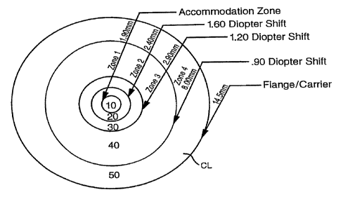
Referring to Fig. l, shown is a first preferred
embodiment of a contact lens CL according to the present
invention. The contact lens CL is divided into a
central circular region and four concentric ring shaped
regions. The central region 10 will be referred to as
zone 1, the accommodation zone, or the sweet spot. The
immediately adjacent first ring shaped region 20 will be
referred to as zone 2. The second ring shaped region 30
immediately adjacent to zone 2 will be referred to as
zone 3. The third ring shaped region 40 immediately
adjacent to zone 3 will be referred to as zone 4.
12
CA 02233062 1998-03-27
WO 97/12272 PCTlUS96/15589
1 The maximum diameter of a human pupil when it
is fully dilated is approximately 8 millimeters, so that
the ring shaped region 50 of the contact lens extending
radially outwardly from zone 4 is not an optical
surface, but merely functions as a carrier to maintain
the optical surface of zones 1 through 4 in position.
Structurally, the zones can be described as
follows. Zone 1 is preferably approximately 1.5 to 1.9
millimeters in diameter. Zone 2 and zone 3 are both
preferably approximately .5 millimeters in width. Zone
4 preferably extends outwardly from a radius of
approximately 2.5 millimeters to approximately 2.9
millimeters to approximately 8 millimeters. Thus, the
lens can be described as having a central sweet spot
(zone 1), two .5 millimeter intermediate zones (zones 2
and 3), and a distance zone (zone 4) extending outwardly
from the intermediate zones to the edge of the optical
portion of the contact lens (approximately 8 millimeters
radially outwards from the center). The total diameter
of the contact lens CL will be approximately 13 to
approximately 16 millimeters for a soft contact lens, so
that the carrier 50 will normally extend from
approximately 8 millimeters outwards to approximately
13.5 millimeters to approximately 15.0 millimeters, and
optimally 14.5 millimeters.
If this invention is practiced in connection
with a hard contact or RGP lens, the total diameter of
the contact lens CL would be between approximately 7.0
millimeters and approximately 11.0 millimeters, and
typically between approximately 8.0 millimeters and
approximately 10.5 millimeters, and optimally
approximately 9.5 millimeters.
Zone 1, the sweet spot, is preferably
spherical, although it can be aspherical. Zones 2, 3
and 4 are preferably aspherical in order to accommodate
transitions in corrective power across these zones.
13
CA 02233062 2001-10-25
1 Conventional contact lenses consist of a
carrion with a central lens portion. The central lane
portion ie usually corrected for distance vision. This
is described in U.S. Patent No. 4,199,231, Evens.
Tho present invention differs from conventional
multifocal contact lenses in that a small control
portion of the lens is overcorrected beyond the
correction that Would be neceeeary for reading. This
central portion, the awowt spot or accommodation cone,
is small enough so that, surprisingly, it doos not
impair distance vision when the user 1e looking at
distant objects, but It restores the ability to focus on
near objects within a~ substantial tango of distances
from tho wearer, such as, between 8 inches and 15
inches. It is believed that the transition zones
restore the ability to focus as follows: sons 2
restores the intermediate visual acuity bwtw~een
approximately 15 inches and approximately 36 inches, and
zone 3 restores the intermediate visual acuity between
approximately 36 inches and full distnnee correction
(infinity).
in determining the appropriate curvatures for
the various zones in the contact lens CL, the correction
to restore distance vision must be determined first.
The distance power correction is then applied to Bone
The distance pv~er correction is usually within a range
betwson +20.00 dlopters to -20.00 dioptvrs.
After the distance cozrection is determined,
the amount of correction for near vision ("add.power")
should be calculated. h parson with early to moderate
preebyopia would bQ prescribed a low additional reading
power of up to +1.75 diopters (referred to no a "low
add~). A moderate to advanced presbyope would require a
reading correction from 1.75 to 1.75 diopters (referred
to ee a "high add").
1~
CA 02233062 1998-03-27
WO 97/12272 PCT/LTS96/15589
1 For a high add presbyope, the aggregate change
in powers across the various zones is preferably
approximately 3.7 diopters. For a low add presbyope,
the aggregate change in powers across the various zones
is preferably approximately 2.6 diopters {approximately
70~ of the total diopter shift for a high add).
The corrective power of the various zones
preferably does not remain constant within each zone.
Instead, for a high add presbyope, it is preferred that
there be as 1.6 diopter shift across zone 2, a 1.2
diopter shift across zone 3 and a .9 diopter shift
across zone 4, so that the total diopter shift across
zones 2, 3, and 4 is 3.7 diopters.
Because the sweet spot is so small, and because
it must be centered in the pupil in order for the
invention to function properly, the contact lens CL must
be precisely manufactured in order to be sure the sweet
spot is properly centered over the center of the pupil.
In order to accomplish this critical centering, it is
preferred to mark a 1.9 millimeter centered spot,
preferably white, on a pair of trial diagnostic contact
lenses. With such a pair of trial diagnostic contact
lenses, it is possible to detect whether a user's pupil
is off center (and other problems), so that the contact
lens of the present invention can be properly
manufactured to center the sweet spot over the pupil.
The inventor has discovered that an
overcorrected central portion of between approximately 1
to approximately 2.5 millimeters, and preferably
approximately 1.5 to approximately 1.9 millimeters
(optimally either 1.5 millimeters or 1.9 millimeters) in
diameter does not substantially impair distance vision
of a contact lens. Surprisingly, the inventor also has
discovered that overcorrecting the central portion
beyond the correction needed for near vision, restores
an unexpectedly large portion of the function of natural
CA 02233062 1998-03-27
WO 97/12272 PCT/US96/15589
1 accommodation of the eye so that focus can be achieved
over a range of near distances.
Although, other contact lenses are known with
central areas that are differently corrected than
distance portions, those central segments are either
larger than the present invention's "sweet spot," or
they do not overcorrect the sweet spot, or both.
It is preferred that the various zones have
constant widths even if the size of the sweet spot
differs. Thus, if the sweet spot is 1.9 millimeters in
diameter, the diameters of zones 2, 3, and 4 would all
be approximately .4 millimeters greater than the
corresponding diameters in a lens with a 1.5 millimeter
diameter sweet spot. It is also preferred that the
diopter shifts between zones 2, 3, and 4 remain constant
regardless of the size of the sweet spot for
mature presbyopes. Fig. 2 shows a contact lens
according to the present invention with a smaller sweet
spot.
For early presbyopia, the amounts of the
diopter shifts across zones 2, 3, and 4 are preferably
approximately 70~ of the diopter shifts for mature
presbyopes. Thus, the preferred aggregate diopter shift
for early presbyopes is approximately 70$ of the diopter
shifts for mature presbyopes. Thus, the aggregate
diopter shift across zones 2, 3, and 4 would be
approximately 2.6 diopters; the diopter shift across
zone 2 will be approximately 1.1 diopters; the diopter
shift across zone 3 would be approximately .8 diopters
and the diopter shift across zone 4 would be
approximately .6 diopters. Figs. 3 and 4 show contact
lenses for early presbyopes with large and small sweet
spots.
Although it is presently preferred to have
intermediate zone 2 and 3, it is not known whether the
presence of such zones is critical to the invention.
Further, it is not known whether the manner in which the
16
CA 02233062 1998-03-27
WO 97/12272 PCT/US96/15589
1 diopter shift is achieved by the aspheric shape of the
various zones is critical. At present, it is preferred
_ that the diopter shift take place at a constant radial
rate in each zone, so that there is a different constant
diopter shift rate in each of zones 2, 3, and 4.
t
However, it is also possible that the benefits of this
invention may be achievable by using varying diopter
shift rates within a zone, or to increase or decrease
the number of zones.
Further, it is not believed to be critical that
the diopter shifts be effected by shaping the contact
lens. For example, it is possible to achieve the
diopter shift by using material with differing indices
of refraction in various different portions of the lens.
Z5 Indeed, with appropriate control over the diffusion of
materials with different indices of refraction during
molding of contact lenses, it is possible that the
present invention could be practiced with a lens that is
spherical or that does not have differently formed lens
portions.
The sweet spot is preferably overcorrected
between 25$ and approximately 100 stronger than the
prescribed reading correction requirement.
For example, for a high add, it would be
preferred that the sweet spot be from 3.5 to 5 diopters
more plus add power than the distance zone (zone 4),
between 3.5 to approximately 3.9 diopters being even
more preferred, and approximately 3.7 diopters being
optimal. For a low add, it would be preferred that the
sweet spot be from 2.0 to 3.5 diopters more plus add
power than the distance zone (zone 4), with between
approximately 2.4 and approximately 2.8 diopters being
more preferred, and optimally approximately 2.6
diopters.
17
CA 02233062 1998-03-27
WO 97/12272 PCT/US96/15589
1 EXAMPLE 1
A Microturn 9000 three axis radius lathe with
aspheric surface cutting capabilities has been used to
make contact lenses according to the present invention
with base curves of 8.6 millimeters wet (6.6 millimeters
dry). The lenses were manufactured dry from Ocufilcon B
(a 53~k water content material) and were hydrated
afterwards. Therefore compensating calculations were
made to achieve the appropriate hydrated parameters,
such as base curve, radial expansion, linear expansion,
power changes due to changes in index of refraction
caused by hydration. When hydrating Ocufilcon B, the
linear expansion parameter is approximately 1.35, the
radial expansion parameter is approximately 1.30, and
the power change parameter is approximately .57. The
settings for the various radii of curvature in the
various zones (for dry manufacturing using Ocufilcon B)
are shown in the following cutting charts:
8.60 high add minus tower
Zone 1 2 3 4
CENTER 1. i0 1.50 1.90 6.00 DIA. C.T. DIST.
POWER 1.40 1.80 2.20 6.00 DIA. C.T. POWER
p1 6.73 6.98 7.17 7.30 .16
.25 6.77 7.02 7.21 7.35 .16
.50 6.83 7.06 7.25 7.40 .16
.75 6.86 7.11 7.29 7.46 .16
-1.00 6.90 7.15 7.33 7.50 .16
-1.25 6.93 7.18 7.37 7.53 .16
-1.50 6.96 7.22 7.41 7.58 .16
-1.75 7.00 7.25 7.45 7.62 .16
-2.00 7.05 7.29 7.49 7.66 .15
-2,25 7.09 7.33 7.53 7.70 .15
-2.50 7.13 7.37 7.58 7.75 .15
-2.75 7.17 7.41 4.62 7.79 .15
18
CA 02233062 1998-03-27
WO 97/12272 PCT/US96/15589
1 -3.00 7.21 7.46 7.67 7.84 .14
-3.25 7.24 7.51 7.71 7.89 .14
-3.50 7.28 7.56 7.76 7.94 .14
-3.75 7.31 7.60 7.80 7.99 .14
-4.00 7.35 7.65 7.85 8.04 .13
-4.25 7.38 7.70 7.90 8.07 .13
8.60 gh add plus
hi power
Zone 2 3 4
1
CENTER I.10 1.50 1.90 6.00 DIA. C.T. DIST.
POWER 1.40 1.80 2.20 6.00 DIA. C.T. POWER
p1 6.73 6.98 7.17 7.30 .16
+.25 6.71 6.95 7.13 7.27 .17
+.50 6.68 6.91 7.09 7.23 .17
+.75 6.65 6.87 7.05 7.19 .17
+1.00 6.62 6.84 7.02 7.16 .17
+1.25 6.59 6.80 6.98 7.12 .17
+1,50 6.56 6.77 6.94 7.08 .17
+1.75 6.52 6.73 6.90 ?.04 .18
+2.00 6.49 6.70 6.87 7.00 .18
+2.25 6.46 6.66 6.83 6.96 .18
+2.50 6.44 6.63 6.80 6.93 .18
+2.75 6.40 6.59 6.76 6.89 .18
+3.00 6.37 6.56 6.72 6.85 .19
+3.25 6.34 6.53 6.69 6.80 .19
+3.50 6.31 6.50 6.66 6.75 .19
+3.75 6.28 6.47 6.62 6.73 .20
+4.00 6.26 6.44 6.59 6.70 .20
+4.25 6.23 6.41 6.56 6.67 .20
8.60 low add plus power
Zone 1 2 3 4
CENTER 1.10 1.50 1.90 6.00 DIA. C.T. DIST.
POWER 1.40 1.80 2.20 6.00 DIA. C.T. POWER
19
CA 02233062 1998-03-27
WO 97/12272 PCT/US96/15589
1 p1 6.73 6.93 7.06 7.17 .16
+.25 6.70 6.89 7.02 7.13 .17
+.50 6.67 6.85 6.98 7.10 .17
+.75 6.63 6.82 6.93 7.06 .17
+1.00 6.60 6.79 6.89 7.02 .I7
+1.25 6.58 6.74 6.86 6.98 .17
+1.50 6.56 6.70 6.84 6.95 .17
+1.75 6.52 6.67 6.80 6.91 .I7
+2.00 6.49 6.64 6.77 6.87 .18
+2.25 6.46 6.61 6.73 6.83 .18
+2.50 6.43 6.58 6.70 6.79 .18
+2.75 6.40 6.55 6.66 6.75 .18
+3.00 6.37 6.52 6.63 6.72 .19
+3.25 6.34 6.48 6.60 6.68 .19
+3.50 6.31 6.45 6.57 6.65 .20
+3.75 6.28 6.42 6.54 6.62 .20
+4.00 6.26 6.39 6.51 6.59 .20
+4.25 6.23 6.36 6.47 6.56 .20
8.60 low add minus tower
Zone 1 2 3 4
CENTER 1.10 1.50 1.90 6.00 DIA. C.T. DIST.
POWER 1.40 1.80 2.20 6.00 DIA. C.T. POWER
p1 6.73 6.93 7.06 7.17 .16
.25 6.77 6.96 7.10 7.21 .16
.50 6.81 7.00 7.14 7.25 .16
.75 6.85 7.03 7.18 7.29 .16
_1,00 6.89 7.07 7.22 7.33 .16
-1.25 6.93 7.1I 7.25 7.37 .16
-1.50 6.97 7.15 7.29 7.41 .16
-1.75 7.01 7.19 ?.33 7.45 .16
-2.00 7.05 7.24 7.37 7.50 .15
_2,25 7.08 7.28 7.41 7.54 .15
-2.50 7.12 7.32 7.46 7.58 .15
-2.75 7.16 7.36 7.51 7.62 .15
CA 02233062 1998-03-27
WO 97/12272 PCTIUS96/I5589
i -3.00 7.20 7.40 7.55 7.67 .14
-3.25 7.23 7.44 7.59 7.7i .14
_ -3.50 7.27 7.48 7.64 7.76 .14
-3.75 ?.31 7.52 7.68 7.80 .14
-4.00 7.35 7.57 7.73 7.85 .13
_ 7.39 7.61 7.77 7.89 .13
-4.25
It is preferred that the contact lenses conform
to industry standards for inside radii, which for soft
contact lenses are presently between 7.5 and 9.5
millimeters, and typically between 8.30 millimeters and
8.6 millimeters. For RGP and hard lenses, the industry
standard inside radii are between 7.0 millimeters and
8.5 millimeters, and typically between 7.3 and 8.2
millimeters.
It is presently preferred that the contact lens
of the present invention comprise conventional soft
contact lens material, such as Ocufilcon B with 53$
water content, because contact lenses have been
successfully manufactured using this material. However,
any conventional soft or rigid contact lens material may
be used to practice the invention (as long as
appropriate compensations are made for parameters that
may change during hydration for soft contact lens
material). The inventor believes that Benz 55G or
Methafilcon A may be as good as, or better than,
Ocufilcon B in the practice of the present invention,
but no lenses according to the present invention have
yet been made with these materials.
While the present invention has been disclosed
in connection with the presently preferred embodiments
described herein, it should be understood that there may
be other embodiments which fall within the spirit and
scope of the invention as defined by the claims. For
example, this invention can be practiced with contact
lenses that are made by any method now known or
21
CA 02233062 1998-03-27
WO 97/12272 PCT/US96/15589
1 hereafter invented, including (but not limited to)
molding, spin casting, or extruding. This invention
also can be applied to intraocular lens implants and
refractive surgical procedures (including radial
keratotomy, photo refractive keratotomy, and corneal
implantation) that reshape the cornea. Furthermore,
this invention can be practiced in combination with
spherical or astigmatic {toric} contact lenses. Toric
lens prescriptions comprise spherical power corrections,
usually between +20 and -20 diopters (commonly between
+8 and -8 diopters), and cylindrical power corrections,
usually between .S diopters and 10 diopters (commonly
between 1 and 4 diopters). The present invention can be
practiced within this entire range of toric (astigmatic)
lens prescriptions. Accordingly, no limitations are to
be implied or inferred in this invention except as
specifically and explicitly set forth in the claims.
Industrial applicability. This invention can
be used whenever it is desired to provide a contact lens
that corrects for distance vision as well as near and
intermediate vision.
30
22