Note: Descriptions are shown in the official language in which they were submitted.
CA 02233068 1998-03-26
W O 97/11742 PCTAUS96/15535
ION~3P~ O~UEllC DRUG DELrVERY
SYSTEM,nN{~nDnNG DISE~SABLE PATY~
pTlll'S.n Op q~5! ~sTION
S The present invention generally relate~ to icntophoretic
dl~lg delivery system~ ~or deliverin~ drugs, medicines,
medicaments and the iike t~ patien~ t-a~er~-lly, i.e.,
through the ~kln, a~d more 8peci~ically rel~tes to a
dispos~ble patch. interconnec~ible with a controller.
r~ o~-n OF IEC5
Tr~n~ r~l drug deliYery 8y8tem~ ha~e, in recent year~,
become ~n lncre~ingly impQrtant ~ean~ of ~ ni~tering drugs
~nd like therapeutic agent~.
Pre~ently, there are rwo types G~ tran~derma; d~rug
delivery ~y~tem~, i.e., "Pa5~lve- an~ "Acti~e.~ Pa~i~e
~yste~s deliver drug through the ~kir of the ~er ~ e~, an
~Y~mple of wh~ch woul~ ln~olve the application of a topic~l
anesthetic to pro~ide loc~l~ zed relief, a~ dicclo8e~ in U. S .
2~ ~Patent No. 3, 814, C95 (r,u~en~ . Acti-re ~yste.ns on the other
hasld deliver d~g through the ckin o~ the user u~ing, i~or
~'Y~"'r~e, iontophore9iE~, which according to Sted~r'6 Medical
Dicti~ary, 1~ de~i~ed a8 "the introduc;ion into the ti~sueC~
by meanY of an electric current, of th~ ion~ o~ a choeen
25 medica~r~nt, n Such Elyl3tem9 of ~er ad~ant~ges clearly not
Achie rable ~y any oth~r metho~s o~ ~3fl~ n1 ~tratlon, such a8
a~oi~ing introduction of the drug through the gastro-
intesti~al traLct or punctures in the ~kin to narne a :Eew.
ConYenticnal ~'ontophcretic devices, such a~ those
de~ribe~ ln U.S. Eate~t Nos. 4,820,~63 ~qpe~ak et al.),
4,927,4~B ~Aaak et al.~ and ~,084,G08 (Phipp~, the
di~clo6ures o~ which are hereby inco~1porated by referenc~, ~or
deliveri~g a drug or medici~e tr~n~rm~ 1 1 y through
tontophore~is, basiCally con~i~t of two electro~es, whlch are
i~ contace with a portion O~ a p~tient' 8 body. ~ f ir~t
electrode, generally called the ~c~ive electrcde, deli~r9 the
SUBSTITUTE SHEET tl2ULE 26~
CA 02233068 l998-03-26
WO97/11742 PCTAUS96/15535
ionic subst~nce or drug in~c tne body by iontophoresi~. The
~e~onA electrode, generally called the coun~er electrode,
closes an electri~al clrcuit trat includes the ~irst electrode
and the patientl~ body. Ge~erally, the circuit in~ludes a
~ource of electrical energy, ~uch ~8 a battery. The ionic
su~stance to be driven into the body may be either positively
charged or negatively charged. In the case o~ a po~iti.vely
charged ionic sub~tance, the anode o~ the io~tophoretic de~ice
become~ the active electrode and the cathode ~erves ac the
cou~ter electrode to complete the circuit. Altercati~ely, i~
the lonic su~stance to be iontophoretically delivered i9
negati~ely charged, the cathode w~l be the acti~e elscrrode
and the an~de will ~e the counter electrode.
In practlce,. thi~ proce~ i8 typlcally achie~ed by
1~ placi~g the ionic drug either -n ~olution or in gel ~orm on a
carrier and placi~g the dr~g-ccnt~n~ns carrier, ~or ~Y~rl~,
in the ~orm o~ a ~rug-~illed A~h~e p~tch, ;~to contact with
the ski~. The pair o~ e}ectrodes i6 placed in o~nt~t uith
the skin and with the carrier. Direct curre~t is applied
~etween ~he two electrOdQs. 'Jnaer the ~nfluence o_ the
electric $ield present, the drug mo~ecule3 rigraee through the
skin. A~ current rlows bet~een the two electrode~ placed at
~paced apart locatio~s o~ the skin, the current p~th carries
the drug wlth ~t.
2~ In order to deliver the dnug to the patient, the adhesive
patch may be applied to the de~ired portion o~ the patient'~
body ~nd the controller att~c~e~ to the patch. O~tsnt~~s the
CO~troller iY a~ large aY, or larger than, ehe patch. It al80
~hould be s~mehow secured in place on the patlent 80 that the
patient may remain mo~lle ~nd carry both the patch and
controller with him as he move~ about.
Hu.~ver, in situat~o~s where the iontophn~etic device is
to be app'ied by the patient, or the de~ice i8 ta be used by a
health care pro~e~sional with a multitude of patients, it would
be help~ul to such u6ers to be ~ble to insure that the de~ice,
particularly the drug-filled patch, has not bee~ Fre~iously
- SUBSTITUTE SHEET (RULE 26)
CA 02233068 1998-03-26
WO97/11742 PCT~S96/15535
u~ed so that the pa~ient actual'y receive~ the ~L~e~ amount o~
- drug. For ~x~mr~, it would ~e ben~icial if the ~eYice could
~ ln~cate to the user whether the device is operat~on~l and
whether it iB ~ctually delivering the ~rug to the patient.
Thus, there has been a ne~G 'or an iontophoretlc drug
deli~ery sy~tem, particularly a disposable patch which would
eli~;n~te the probl~m~ and lim~ tation~ assoclated with the
prlor device~ di~cus~ed above, most 8ign~ ~icant o~ the
~ro~lem~ being ~s~;~ted with a~tempt~ to reu~e a patch.
~132L'~Y ~F T~ I~V~ ON
In contrast to the prior devices and ~y~tem6 di~cu~ed
above, it has been ~ound that a iontophoretic drug delivery
system including a disposable patch which ~ay be constructed
in a_cordance with the prese~_ i~ention i~ particularly
suited for ~ ~v~,.ting reuse o~ a patch. In addition, the
~po~hle patch Q~ the present invention pre~erably can be
ea~i7y att~che~ to the controller3 for delivcring the drug,
medicine, medicament or the like.
20 ~ T~e dispo~able patch of the pr~sent invention ~or use i~
~n~t~on ~ith a controller to form an oper~hle iontophoretic
drug delivery gystem includes a ~1 An~r body portion including
at least a ~irst electrode a~se~bly and a ~eco~ electrode
a~eembly, and the first electrode as~e~ly ~aving a ~lrst
2~ electrode and a gecon~ electrode both in contact with and
adjac~n~ to a drug filled re~ervoir, whereby when the patch i8
electrically connected to the controller, electrical ~r I e~t
initially ~l~w8 throuyh the ~irst electrode aceembly from the
~econd electrode to the ~irst electrode ~d therQa~tar fr~m the
~0 cecond electrode as~embly ~o the ~irst electro~e.
I~ the preferred embo~; ~n, ~ the disro~ e patch further
includeg electrical interconnection means for interconnecting
the ~ody portion with a controller. Alco, ~he body portion
includeg a tab having a plurality o~ electrical t~aces thoreon
in electrical c~m~n~cation with the electrod~ ~scemblie~ and
the elec-rical ~nterCODneCtiOn ~ean~. In addltion, at least
SUBSTITUTE SHEET (RULE 26)
CA 02233068 l998-03-26
WO97/11742 PCT~US96/15535
one o~ the electrical traces interconn~cting the ~ir~t
~ electrode and i~terconnectible wlth the electrical
interconnectlon mR~n6 includes a resistor.
The iontophoretic drug de'lvery ~ystem of the present
S in~ention incl~des a drug-~ lled patch removably att~ch~hle to
the skin of ~ patient for ion~ophoretically deli~erLng at
leact one dr~g to the patient, w~th the patch including
electrical interconnection means for interconnecting the patch
with the contro;ler, a cor.troller L~-ovdbly, electrically
connect~ble to the p~tch, the controller pro~lding ~ufficient
energy to the patch t~ drive the ionized medicament into the
~kl~ of the patient an~ the controller including electronic
means for monit~ring and control~iny electric~l current
supplied to the patch, and the patch including at lea~t a
~irs~ electro~e assembly ar.d a second electrode a88e~1y, with
the ~irst electrode assembly ha~ing a -fir8t electrod~ and a
~econ~ electrode ~oth in contact with and ad~acent to a drug
filled re~ervoir, wl-~r~by when the patch is electrically
con~ected to the controllcr, electrical currant lnitlally
~l~w~ t~rough the ~irst electrode a~sembly fro~ the 8~C~
electrode to the first elsctrode and therea~ter ~rcm the
~econd electrode ac~embly to the irst electrode.
~T~ D3~r7~ A- OF T~ n~IN~9
2S The various fea~ure~, ob~e~, bene~its, and advantages
c~ the pre~ent in~ention wil} become ~ore apparent upon
reading the ~ollowing deta~led descrlption of the pre~erred
~mh~;m~nt along with the appended cl~imR in conjunction with
the drawingc, wherein like ~eference n~erals identi~y
corre~pon~;n~ compo~nt~, ard:
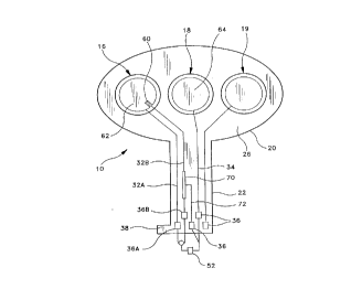
~ igure 1 is top view o~ the patch o~ the present
inve~tlo~;
Figure lA i~ a ~ide view ~ the patch shown in Fisure 1;
~ igure 2 i~ an perspective view o~ the patch
interc~nnected with a contraller; and
SUBSTITUTE SHEET (RULE 26)
-
CA 02233068 1998-03-26
_ Figure 3 is a perspective view of the patch and
contraller attached to the skin of a patient
~ETAILED DESCRIPTION OF THE PREFERRED EMBODIMENT
The iontophoretic drug delivery system of the present
invention is illustrated in Figures 1-3, with the patch
generally designated 10.
Referring to Figures 1-3, the patch 10 of the present
invention for use in the iontophoretic drug delivery system
is electrically interconnectible to a controller 12 to form
the operable system, with the patch, along with the
controller, being attachable to the skin of a patient 14
(Figure 3). The patch typically includes an active
electrode assembly 16 and a counter electrode assembly 18.
lf a positively charged medicament is to be delivered to
the skin 14, the medicament would be positioned in the
active electrode assembly. In the preferred embodiment, a
third or adjunct electrode assembly 19 is provided so that
when delivering a local anesthetic such as Lidocaine, the
local anesthetic may be delivered beneath the counter
electrode as well as the active electrode as disclosed, for
example, in international Patent application, entitled
"lONTOPHORETIC DRUG DELIVERY DEVICE HAVING IMPROVED
CONTROLLER AND PATCH," published 11 April 1996 under
~096/10440, the disclosure of which is hereby incorporated
by reference in its entirety.
As illustrated in Figures 2 and 3, the patch 10 is
coupled to the controller 12 using well known means, for
example, by printed flexible circuits, metal foils, wires,
tabs or electrically conductive adhesives as disclosed for
example in International Patent Application, Publication
No. WO96/10440, published on 11 April 1996 entitled
"IONTOPHORESIS DRUG DELIVERY DEVICE HAVING IMPROVED
CONTROLLER AND PATCH."
A!~E.?~ 3 S~
CA 02233068 1998-03-26
. .
- Referring to Figures 1 and lA, the patch 10 is a
generally planar flexible member and may be adhesively
supported on the skin 14 of the patient (Figure 3). The
patch 10 includes an enlarged patch body 20 and an
extending narrow tab 22. The patch body 20 includes opposed
planar surfaces 24 and 26, with the planar surface 26
disposed for skin contact and including a drug reservoir 28
typically in a gel form which contains at least one drug,
medicament, medicine or like active agents (hereinafter
collectively referred to simply as drugs), preferably in an
ionic form and possibly an adhesive layer 30. While the
drug reservoir 28 is shown, any other known iontophoretic
drug reservoir structure for placing a medicament in
contact with the skin in an iontophoretic patch may be
employed, as disclosed for example in International Patent
Application, Publication No. WO95/09031, published on 6
April 1995, entitled "IONTOPHORETIC DEVICE, RESERVOIR AND
METHOD OF M~KING," the disclosure of which is hereby
incorporated by reference in its entirety.
Each of the electrode assemblies 16 and 18 are
positioned to be in contact with the skin once the patch 10
is secured, as shown in Figure 3. The positioning of the
electrode assemblies 16 and 18 is such that an electrical
current path is established between the electrode
assemblies 16 and 18 through the skin of the patient 14. A
direct current source in combination with the electrode
assemblies 16 and 18 and the patient's body 14 completes
the circuit and generates an electric field across the body
surface or skin to which the iontophoretic device is
applied, with the drug reservoir 28 assumes the same charge
as the ionized drug contained in the reservoir 28. Under
the influence of electrical current passing from the
electrode assembly 16 through the skin 14 to the electrode
assembly 18, the drug contained in the drug reservoir 28 is
transcutaneously delivered into the body of the patient by
A~ ~~ ~ET
CA 02233068 1998-03-26
the pr~scess of iontophoresis.
Referring to Figures 1 and 2, the electrical current
is supplied from the controller 12 to the electrode
asse~blies 16 and 18 on the patch via the electrical traces
or leads 32 and 34 (Figure 1). Each of the traces 32 and 34
may be one or more conductive paths extending from the
electrode assemblies 16 and 18 to exposed conductive pads
36 positioned on a marginal edge of the patch tab 22. The
pads 36 are positioned for electrical connection to the
controller 12, which provides a source of electrical
current as disclosed in International Patent Application,
Publication No. WO96/10440 published 11 April 1996,
entitled "IONTOPHORETIC DRUG DELIVERY DEVICE HAVING
IMPROVED CONTROLLER AND PATCH."
As previously indicated, when using a patch,
preferably the patch 10 includes a means for insuring that
a patch is not reused. Accordingly, as illustrated in
Figures 1 and lA, the patch 10 of the present invention,
particularly the active electrode assembly 16, includes an
additional counter electrode 60, which depending upon the
ionic charge of the drug, will either act as a cathode or
an anode. Thus, since the controller includes the
electronics, and more particularly, the microprocessor, the
controller upon being activated can deliver electrical
current via conductive pad 36B along electrical trace 32B
to the counter electrode 60, whereby the electrical current
flows through the reservoir 28 surrounding the electrode
assembly 16 to the electrode 62 along electrical trace 32A
to conductive pad 36A. In this way, the electrode assembly
16 acts as a miniature iontophoretic device for a limited
period of time during which a small amount of consumable
material is transported to the electrode 62. Upon depletion
of the consumable material, current will no longer be
conducted along this electrical pathway. Then after a
predetermined or preselected period of time sufficient to
' CA 02233068 1998-03-26
;,,~. ..- ~
excee~d- the amount of time necessary to deplete electrode
60, electrical current is supplied along the pathway formed
by electrical traces 34 and 32A.
Also, a resistor 70 may be situated along electrical
trace 32B and interconnected through the controller 12 by
electrical trace 72, in this way, the controller, among its
other functions, may monitor the electrical voltage drop at
the resistor 70, and if none is present, the controller
will not fully activate the patch for delivery. ln this
way, it can be assured that the appropriate patch is with
the appropriate controller as disclosed in International
Patent Application No. WO96/10440, published 11 April 1996,
entitled "IONTOPHORETIC DRUG DELIVERY DEVICE HAVING AN
IMPROVED CONTROLLER AND PATCH."
Also, in this way if the controller (12) is to be used
with several different types of patches, it may monitor the
electrical voltage at lead 72 and if it is within a
predetermined range associated with a particular patch
design, the controller can identify the type of patch
connected and the corresponding current profile to be
supplied. For example, a controller which is specifically
programmed to provide current to a patch administering a
specific medicament may need to operate at a certain
current level for two hours in order to deliver the proper
dosage when attached to one type of patch. In this way, the
controller can be used with a variety of patches, and know
which patch it is connected with, and likewise if an
inappropriate patch is connected fail to activate the
system. In this way, it can be assured that the controller
is used with the appropriate patch.
To provide the user with the above information, the
controller may include an indication means, such as LED's
80, to visually indicate to the user whether the system is
operating and, when appropriate, that either a used patch
is connected or an inappropriate patch is connected. The
~ CA 02233068 1998-03-26
~ _ 7 :~ ~
. ~ ' ' t , ~ ~
LED'-s -are electrically coupled to the microprocessor so
that information received and stored by the microprocessor
can be transmitted via the LED's to a user, technician or
health-care professional. The stored data may also be
transmitted by the LED's to a computer and dlsplayed using
any known means such as the display of the computer. The
circuitry for performing the transmitting and receiving
using LED's is well known to those skilled in the art and
any such known circuitry may be used to accomplish this
feature.
As a result of the above, the user can thus be assured
that patches are not reused and that the appropriate patch
is used to provide increased safety. Also in this way,
costly methods and electronics to read serial numbers and
the like can be eliminated reducing the cost of the
controller.
The particular construction of the patch 10 is not
essential to the present invention, and may be formed of
woven or non-woven textiles or polymers or may be any other
construction well known in the art. However, it is
preferred that the electrode assemblies 16, 18, the
electrical traces 32, 34 and the conductive pads be printed
or otherwise formed on a polymeric substrate.
As illustrated in Figures 2 and 3, the particular
construction of the controller (12) is also not essential
to the present invention and may include a controller
housing 40 having an upper portion 42 and a lower portion
44 pivotably interconnected, with the portions being biased
towards one another by a biasing means such as a spring 46.
In this way, the housing 40 has a general clothespin shape
and includes a biasingly openable front end 48 which
accommodates the tab 22 of the patch 10 as disclosed in
International Patent Application No. WO97/11741 published
on 3 April 1997, entitled "IONTOPHORETIC DRUG DELIVERY
SYSTEM, INCLUDING REUSABLE DEVICE," the disclosure of which
A.~lE~ 'fD S~ ET
~ CA 02233068 1998-03-26
. . , . ~
_ ,',, " :, q '
o
is h-ereby incorporated by reference ln their entirety. The
housing 40 may further accommodate a connectiOn array 50
adjacent the electronics 52 contained within the housing 40
and schematically shown in phantom in Figure 2. The
connection array 50 and the electronics 52 are preferably
mounted to a common printed circuit board (not shown). The
connection array 50 may include plural electrical terminals
in electrical connection with the electronics 52 and may be
connectible to the pads 36 of the tab 20 extending from the
patch 10. As previously discussed, it may be appreciated
that any suitable electrical interconnection device may be
employed in accordance with the present invention.
Referring back to Figures 2 and 3, the controller 12
houses the electronics 52 that monitor and control the
supply of electric current to the electrode assemblies 16
and 18 and the user interfaces. As is known in the art, the
electrical components may include a source of electrical
power such as a battery and additional electronic
components, such as an application specific integrated
circuit, a microprocessor, used to send a controlled
electrical current to electrode assemblies 16 and 18. It
should be appreciated that the particular electronics are
not essential to the present invention, and may include,
for example, those disclosed in International Patent
Application No. WO96/10440 entitled "IONTOPHORETIC DRUG
DELIVERY DEVICE HAVING IMPROVED CONTROLLER AND PATCH
published 11 April 1996 and International Patent
Application No. WO97/11741 entitled "IONTOPHORETIC DRUG
DELIVERY SYSTEM, INCLUDING REUSABLE DEVICE the disclosures
of which are hereby incorporated by reference in their
entirety.
In the preferred embodiment, as illustrated in Figure
2, the patch 10 may be easily interconnected with the
controller 12 under thumb actuation to an open position
exposing the connection array 50 for electrical connection
~ E~l~tD S~.~EE
CA 02233068 1998-03-26
with- ~he pads 36 of the tab 20. Specifically, by pressing
the rear end 49 of the housing with sufficient force to
overcome the spring 46 to open front end 48 of housing 42.
The tab 22 of the patch 10 may then be inserted in the open
end, with the conductive pads 36 slidably engageable with
the connection array 50 and the housing returned to a
closed position by releasing the rear portion to cover the
connection array 50 with the pads clamped or otherwlse held
therebetween.
In order to assure accurate alignment of the pads 36
of the tab 22 with the connection array 50 supported within
the housing 40, the tab 20 is keyed to the housing 40.
Specifically, the tab 22 includes an extending leg or like
portion 38 on one side which is designed to fit in a
corresponding notch (not shown) formed in at least one side
of the front end 48 of the lower portion 42 of the housing.
40. The notch and the leg 38 are of similar shape so as to
provide keyed accommodation of the tab 22 and the leg 38.
The key structure included on both the housing front end 48
and the leg 38 insures proper orientation of the patch 10
and the controller 12 by preventing incorrect positioning
of the patch 10 with respect to the controller 12. In the
present embodiment, both the front end 48 and the notch 54,
and the corresponding tab 22 and the leg 38 have a
generally L-shaped cross-section, however, any other mating
shape which would prevent incorrect alignment may be
employed.
Referring to Figures 2 and 3, the patch 10 and the
controller 12 may also include attachment means for
permitting the releasable support of the controller 12 on
the patch 10 after interconnection between the pads 36 and
the connective array 50 is established. The surface 24 of
patch 10, and the exposed upper portion 42 include
cooperating fastening elements 56 and 58 thereon. ln the
present illustrative embodiment, the cooperative fastening
,i ~'L ' t.J ~
' CA 02233068 1998-03-26
,. ~ ~ e ~
': : ;: ' ', .
elem~ts 56, 58 lnclude conventional hook and loop
fasteners of the type sold under the trademark VELCRO. Any
other cooperating type fasteners may be employed to achieve
the same objective. One cooperating fastening element 56 is
secured adhesively or otherwise to patch 10 on surface 24
while the other cooperating fastening member 58 is secured
by adhesive or otherwise to the exposed surface of upper
portion 42 of the housing 40. As described in further
detail below, attachment or the mating hook and loop
fasteners 56 or 58 provide removable support for controller
12 on patch 10. It may be appreciated by those skilled in
the art that the patch and controller may take any known
form. The only requirement is that the patch be capable of
being physically and electrically connected to the
controller 12.
Operation
~nd Use
Having described one embodiment of the iontophoretic
drug delivery system, including the disposable patch 10, of
the present invention, its operation and use is described
below.
As illustrated in Figure 3, the patch 10 and the
controller 12 may be adhesively secured to the skin 14 of
the patient, with surface 26 of patch 10 placed in intimate
contact with the skin 14 so that the electrode assemblies
16 and 18, as well as the drug containing reservoir 28, are
supported in intimate contact with the skin 14. In order to
iontophoretically deliver the medicament from reservoir 28
transcutaneously through the skin 14, the controller 12 is
electrically connected to patch 10. The housing 40 is
opened and the tab 22 of the patch 10 is inserted into the
open front end 46 of the housing 40 (Figure 2). As the
controller 12 is designed to be maintained in electrical
connection with the patch 10 during iontophoretic delivery
r~ C~ 3 ~ '
CA 02233068 1998-03-26
~ ~; , , ;
of th~ drug contained in the reservoir 28, the controller
12 may then be fastened or otherwise attached to the patch
10 so that it will be conveniently retained on the skin of
the patient (Figure 3).
Thereafter upon activation of the system, electrical
current will initially flow through trace 32B, electrode
60, electrode 62 and trace 32A. During which time, the
consumable material on electrode 60 will preferably be
exhausted and the controller will monitor whether
electrical current is flowing, in which event the
controller will then stop delivery of current along this
pathway, and switch to delivering current through trace 34,
electrode 64, electrode 62 and trace 32A, and the LED 8OA
would be preferably activated to indicate operation of the
system. However, if the controller 12 did not detect the
delivery of current during the initial period of time, the
LED 80B would preferably be activated to indicate that the
system was not operational.
At such time as a particular application of the drug
delivery system is completed, the patch 10 and the
controller 12 may be removed from the skin of the patient
and disconnected form one anther. In this way, the used
patch 10 can be disposed of and the controller 12 placed
aside until the next administration of the drug is needed,
when it can be reused with a new patch.
In the preferred embodiment, the patch 10 of the
present invention contains Lidocaine (a local anesthetic)
and Epinephrine or Adrenaline (vasoconstrictors). In this
way, the device can be used for anesthetizing the applied
area to minimize sensation from the insertion of a needle
or the like. However, it should be appreciated that other
substances suitable for being applied to the area may be
utilized which are well known to those skilled in the art.
Active agent, drug, formulation, medication, medicament and
active compound have been used herein to mean any ethical
! CA 02233068 1998-03-26
'': ' ;.' : ~
pharm~ceutical compound or agent, such as therapeutic
compounds, diagnostic agents, anesthetic agents and the
like.
As is well known within the field, the device can be
situated on the area of the patient to which the active
agent is to be applied ~the applied area) such as the skin
and a voltage impressed across the electrode assemblies 16,
18 to cause electrical current to flow through the skin of
the patient to drive or otherwise transport the drug
preferably in the form of an ionic active agent into the
skin and the tissue to be absorbed by the body of the
patient. The electric field lines are sufficiently long,
however, so that the active agent is transported to the
desired depth within the skin, and possibly to the
vasculature, to provide the desired effect, e.g.,
anesthetic, therapeutic or diagnostic. It should also be
appreciated that the device of the present invention can be
applied to other areas of the body such as mucus membranes
depending upon the desired therapy and drugs to be
delivered.
In addition, while the present invention has been
described in connection with iontophoresis, it should be
appreciated that it may be used in connection with other
principles of active introduction, i.e., motive forces,
such as electrophoresis which includes the movement of
particles in an electric field toward one or other electric
pole, anode, or cathode and electro-osmosis which includes
the transport of uncharged compounds due to the bulk flow
of water induced by an electric field. Also, it should be
appreciated that the patient may include humans as well as
animals.
14
~~ c,~ r F,