Note: Descriptions are shown in the official language in which they were submitted.
CA 02233101 2002-07-08
- 1 -
A DEVICE HAVING PROCESS, WASTE AND PIPETTE TIP PARKING CHAMBERS
AND A METHOD FOR TRANSFERRING L~UIDS
The invention relates to a method for carrying out a process
wherein a biological sample is processed with one or more
reagents.
The invention relates in particular to a method of this kind
which is suitable for carrying out a process for obtaining a
purified nucleic acid sample from a bio:',c:>gical sample.
The invention further re:Lates to a device for carrying out a
l~J process wherein a bio.l.ogi.cal sample i_.s processed with one or
more reagents,
The invention relates in particular to a device of this kind
which is suitable for carrying out a process for obtaining a
purified nucleic acid sample.
l.~ Known methods f:or obta:zining a purified nucleic acid sample
suitable to be amplified, by, for example, a polymerase
chain reaction (PCR) are usually carried out manually and
involve a number of steps and in part:ic~zlar a pluz:ality of
pi~etting operations. Since contamination of the purified
20 sample to be obtained has to be reduced as far as possible,
the manual process has to be carried out. with great care and
is therefore a time consuming task.
Known apparatus; for automatically carrying out pipetting
operations in analyzer systems have been found inadequate
25 for methods aiming to obtain purified nucleic acid samples
suitable to be amplified, such as by a polymerase chain
reaction (PCR), because contamination of the sample is
likely to occur during pipetting operations.
A main aim of the invention, therefore, is to provide a
30 method and a device t~.> ensure a contamination.-free automatic
processing of :samples and reagents to a degree which is
sufficient to comply wit.: the requirements of nucleic acid
CA 02233101 2002-06-18
(2t~OR2CA 1909021.DOC Prt: 18.06.2002 VE)
2
purification methods which provide nucleic acid samples
having a high degree of purity and being thereby suitable to
be amplified.
According to a first aspect of the invention this aim is
attained with a method wherein a fluid biological sample is
processed with one or more reagents, using a device having a
first process chamber, a waste chamber and a chamber for
parking a pipetting tip, the process comprising the steps of
transferring a liquid from the first process chamber to the
waste chamber, or from a primary sample tube external to the
device to the first process chamber, or from the first
process chamber to a specimen container external to the
device, and wherein said transfer of the liquid is effected
by means of pipetting operations carried out with said
pipette tip.
According to a second aspect of the invention, the above-
mentioned aim is attained by means of a disposable device
which comprises an array of chambers integrally connected to
each other; a cover insert removably connected to the array
of chambers; and a disposable pipetting tip, and said array
of chambers comprises:
an upper portion shaped as an elongated tray and having
an interior delimited by a bottom wall and a side wall which
extends perpendicular to and along the perimeter of the
bottom wall;
a first process chamber having an open top end and a
closed bottom end connected by a tubular wall which extends
substantially perpendicular to the bottom wall of said upper
portion and downwar_dly from a first opening in said bottom
wall, said first opening forming the open top end of the
first process chamber;
a waste chamber for receiving waste liquids, said waste
chamber having an open top end and a closed bottom end
connected by a side wall which extends substantially
perpendicular to the bottom wall of said upper portion and
downwardly from a second opening in said bottom wall, said
CA 02233101 2002-06-18
(26C82CF 190402_.DOC Prt: 1F3.06.2002 ~7E'
3
second opening forming the open top en.d of the waste
chamber;
said cover insert being configured and dimensioned to be
inserted in the array of chambers and said cover insert
comprisingm
an elongated cover having openings providing access to
the process chamber and the waste charr~ber respectively when
said cover insert is inserted in said array of chambers, and
a parking chamber for parking therein said disposable
pipetting tip, said parking chamber having an open top end
and a closed bottom end connected by a tubular wall which
extends substantially perpendicular tc the cover and
downwardly from an opening in the cover;
said disposable pipetting tip being configured and
dimensioned to be at least partially inserted in the
interior of the parking chamber.
The main advantage of the method and of the device according
to the invention is that they make possible to ensure a
contamination-free automatic processing of samples and
2C reagents to a degree which is sufficient to comply with the
requirements of nucleic acid purification methods which
provide nucleic acid samples having a high degree of purity
and being thereby suitable to be amplified, such as by a
polymerase chain reaction (PCR).
A further advantage of the device according to the invention
is that a plurality of these devices c:an be used
simultaneously in an automatic apparatus to obtain a
corresponding plurality cf purified nucleic acid samples
from respective biological samples.
A specific advantage of an embodiment of the device
according to the invention comprising only one process
chamber is that it is cheaper than a device comprising more
CA 02233101 1998-04-O1
(26082CA.DOC Prt: 11.03.1998 KG)
- 4 -
than one process chamber and that the small size of the
device contributes to that less waste material has to be
disposed of after use of the device and reduces also the
cost of packaging material therefor.
A preferred embodiment of the device according to the
invention is characterized in that the cover comprises a
first channel which provides access to the interior of the
process chamber for dispensing a liquid into this chamber,
this dispensing being effected with a pipetting cannula
other than the disposable pipetting tip. The advantage of
this embodiment is that the channel mentioned ensures that
during the pipetting operation the tip of the pipetting
cannula is located within a substantially closed environment
which prevents accidental contamination during the transfer
of liquid from the pipetting cannula to the process chamber.
A further preferred embodiment of the device according to
the invention is characterized in that a substantial part of
the parking chamber is located within the waste chamber when
said cover insert is inserted into said array of chambers.
This configuration advantageously reduces the space occupied
by the device, because no additional space is necessary for
the parking chamber.
Another preferred embodiment of the device according to the
invention is characterized i.n that the process chamber
depends freely downwardly from the bottom wall of said upper
part of chamber array. This configuration offers the
advantage that the lower part of the process chamber is
accessible to external means, e.g. magnets, used to obtain
separation of magnetic particles in suspension in a liquid
contained in the process chamber.
A further preferred embodiment of the device according to
the invention is characterized in that said integrally built
CA 02233101 1998-04-O1
(26082CA.DOC Prt: 11.03.1998 KG)
- 5 -
array of chambers further comprises a second process chamber
having an open top end and a closed bottom end connected by
a tubular wall which extends substantially perpendicular to
the bottom wall of said upper part and downwardly from a
third opening in said bottom wall, said third opening
forming the open top end of the second process chamber. The
advantage of this embodiment is that it offers more
flexibility with regard to the sequence of process steps for
carrying out a particular method. This flexibility is
increased e.g. by maintaining the process chambers at
different temperatures, e.g. one at 60° C and the other at
37° C, and/or by using one of the process chambers for
provisional storage of a reagent before it is transferred to
the other process chamber.
A preferred embodiment of the device according to the
invention and comprising 2 process chambers is characterized
in that the bottom wall of said upper part comprises a
second channel which provides access to the interior of the
second process chamber for dispensing a liquid into this
chamber, this dispensing being effected with a pipetting
cannula other than the disposable pipetting tip. The
advantage of this embodiment is that the second channel
ensures that during the pipetting operation the tip of the
pipetting cannula is located within a substantially closed
environment which prevents accidental contamination during
the transfer of liquid from the pipetting cannula to the
second process chamber.
Another preferred embodiment of the device according to the
invention and comprising 2 process chambers is characterized
in that the first process chamber, the waste chamber and the
second process chamber are arranged in a row. This
configuration advantageously simplifies the arrangement of a
plurality of devices according to the invention in an
automatic processing apparatus and also the transport means
CA 02233101 1998-04-O1
(26082CA.DOC Prt: 11.03.1998 KG)
- 6 -
used for moving the disposable pipetting tip and the
pipetting cannula to their pipetting positions with respect
to the various chambers of the device.
Another preferred embodiment of the device according to the
invention and comprising 2 process chambers is characterized
in that the waste chamber is located between the first
process chamber and the second process chamber. This
configuration advantageously reduces the motion paths of the
disposable pipetting tip and the pipetting cannula necessary
to bring these to their pipetting positions with respect to
the various chambers of the device.
A further preferred embodiment of the device according to
the invention and comprising 2 process chambers is
characterized in that the second process chamber depends
freely downwardly from the bottom wall of said upper part of
chamber array. This configuration offers the advantage that
the lower part of the second process chamber is accessible
to external means, e.g. magnets, used to obtain separation
of magnetic particles in suspension in a liquid contained in
the second process chamber.
Preferred embodiments of the device according to the
invention are characterized in that the array of chambers of
the device according to the invention is a single piece of
plastic material.
Preferred embodiments of the device according to the
invention are characterized in that said cover insert of the
device according to the invention is a single piece of
plastic material.
These preferred embodiments makes it possible to reduce the
manufacture price of the device.
CA 02233101 1998-04-O1
(26082CA.DOC Prt: 11.03.1998 KG)
A preferred use of the device according to the invention is
for carrying out a process characterized in that it
comprises steps of dispensing a liquid reagent from a
reagent container external to the device into the process
chamber, said dispensing being effected with a pipetting
cannula other than the disposable tip which is part of the
device.
A preferred use of the device according to the invention and
comprising 2 process chambers is for carrying out a process
characterized in that it comprises steps of automatic
transfer of liquids from the first process chamber into the
second process chamber or vice versa, or from the first or
the second process chamber to the waste chamber, or from a
primary sample tube external to the device to the first or
the second process chamber, or from the first or the second
process chamber to a specimen container external to the
device, and wherein said transfer of liquids is effected by
means of pipetting operations carried out exclusively with
t:he disposable tip which is part of the device.
A further preferred use of the device according to the
invention and comprising 2 process chambers is for carrying
out a process characterized in that it comprises steps of
dispensing a liquid reagent from a reagent container
external to the device into the first process chamber and/or
t:he second process chamber, said dispensing being effected
with a pipetting cannula other than the disposable tip which
i.s part of the device.
A preferred use of the device according to the invention is
for carrying out a process for isolating a nucleic acid
contained in a biological sample.
CA 02233101 1998-04-O1
(260B2CA.DOC Prt: 11.03.1998 KG)
_ g _
Preferred embodiments of the invention are described below,
by way of example, with reference to the accompanying
drawings wherein:
F'ig. 1 is a perspective view of a first embodiment of device
according to the invention.
Fig. 2 is a view of a cross-section on line II-II in Fig. 1
Fig. 3 is a top plan view of the device according to Fig.
1. .
Fig. 4 is a perspective view of a second embodiment of
device according to the invention.
Fig. 5 is a view of a cross-section on line V-V in Fig. 4
F'ig. 6 is a top plan view of the device according to Fig. 4.
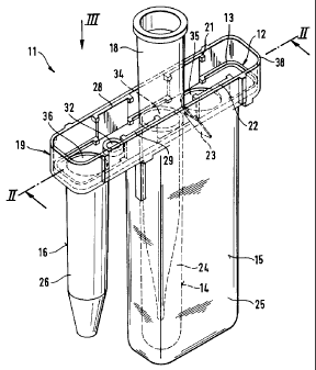
Figures 1 to 3 show a first embodiment of a device 11
according to the invention. This first embodiment comprises
an integrally built array of chambers 19, an integrally
built cover insert 12 and a disposable pipetting tip 18.
Array of chambers 19 and cover insert 12 are assembled
together by inserting cover insert 12 into the upper part of
array of chambers 19. Figures 1 and 2 show this assembly.
Array of chambers 19 comprises:
- an upper part which is shaped as an elongated tray and
which has an interior delimited by a bottom wall 39 and a
side wall 38 which extends perpendicular to and along the
perimeter of bottom wall 39,
- a process chamber 26, and
- a waste chamber 25 for receiving waste liquids.
Process chamber 26 has an open top end and a closed bottom
end connected by a tubular wall 16 which extends
substantially perpendicular to bottom wall 39 of the upper
CA 02233101 1998-04-O1
(26082CA.DOC Pzt: 11.03.1998 KGj
_ g
part of array of chambers 19 and downwardly from a first
opening in bottom wall 39. This first opening forms the open
top end of first process chamber 26. Process chamber 26
depends freely downwardly from the bottom wall 39 of the
upper part of chamber array 19.
Waste chamber 25 has an open top end and a closed bottom end
connected by a side wall 15 which extends substantially
perpendicular to bottom wall 39 of the upper part of array
of chambers 19 and downwardly from a second opening in
bottom wall 39. This second opening forms the open top end
of waste chamber 25.
Cover insert 12 is configured and dimensioned to be inserted
i.n chamber array 19. Cover insert 12 comprises:
an elongated cover 13 having openings 36 and 35 providing
access to process chamber 26 and to waste chamber 25
respectively when cover insert 12 is inserted in chamber
array 19, and
- a parking chamber 24 for parking therein the disposable
pipetting tip 18.
In a preferred embodiment cover 13 includes a jet deflector
23 which has the position shown in particular by Fig. 2 and
which serves for deflecting a jet of liquid pipetted into
waste chamber 25. Jet deflector 23 prevents that such a jet
may impinge directly onto the free surface of liquid already
contained in waste chamber 25. Such impact is undesirable,
because in some cases it may cause splashing and expel some
droplets out of waste chamber 25 through opening 35.
Parking chamber 24 has an open top end and a closed bottom
end connected by a tubular wall 14 which extends
substantially perpendicular to cover 13 and downwardly from
a.n opening 34 in cover 13. In a preferred embodiment the top
CA 02233101 1998-04-O1
(26082CA.DOC Prt: 11.03.1998 KG)
- 10 -
end of tubular wall 14 of parking chamber 24 lies above
cover 13.
Disposable pipetting tip 18 is configured and dimensioned to
be at least partially inserted in the interior of parking
chamber 24. Disposable pipetting tip 18 has a tubular wall
part of which snugly fits into the interior of parking
chamber 24, the lower end of pipetting tip is kept however
at some distance from the bottom and from the side walls of
parking chamber 24.
The upper part of disposable pipetting tip 18 is so
configured and dimensioned that it can be gripped and held
by a suitable pipetting tip-gripper (not shown) which is
part of pipetting tip transport means of an automatic
apparatus (not shown) so that pipetting tip 18 can be moved
by the pipetting tip-gripper to different pipetting
positions within the apparatus. Preferably the pipetting
t:ip-gripper is such that when it grips tip 18 it fluidically
connects this tip with a dosing pipettor (not shown)
included in the automatic apparatus.
In the preferred embodiment shown by Fig. 2 a filter 31 is
located within the upper part of pipetting tip 18. Filter 31
serves to prevent contamination by carry-over of gas or
liquid during pipetting operations.
In the preferred embodiment shown by Figures 1 to 3
pipetting tip 18 is so configured and dimensioned that it
can also be used as closure of the waste chamber 25 when the
lower part of pipetting tip 18 is inserted through opening
into the waste chamber 25.
The shape of cover insert 12 is such that it can be gripped
30 and held by a suitable gripper (not shown) which is part of
transport means of an automatic apparatus (not shown) so
that cover insert 12 and thereby the entire device 11 can be
CA 02233101 1998-04-O1
(26082CA.DOC Prt: 11.03.1998 KG)
- 11 -
moved by the gripper to different positions within the
apparatus, e.g. from a parking position, where an array of
devices 11 is positioned side by side, to an incubator
position.
I:n the preferred embodiment shown by Figures 1 to 3 cover
insert 12 has an array of four tangs 21, 22, 28, 29 arranged
as shown by the figures.
In a preferred embodiment the configuration and dimensions
of this array of tangs and the configuration and dimensions
of the upper part of disposable pipetting tip 18 are so
chosen that the top of the pipetting tip 18 or a couple of
gangs, e.g. 21 and 22 or 28 and 29 can be gripped with the
:>ame gripper.
Cover 13 comprises a first channel 32 which provides access
t:o the interior of the first process chamber 26 for
pipetting into this chamber a reagent from a reagent
container located outside device 11. This pipetting
operation is effected with a pipetting cannula (not shown in
the figures) other than disposable pipetting tip 18.
As shown by Figures 1 and 2 a substantial part of parking
chamber 24 is located within waste chamber 25 when cover
insert 12 is inserted into array of chambers 19.
F~'igures 4 to 6 show a second embodiment of a device 41
according to the invention. This second embodiment comprises
an integrally built array of chambers 49, an integrally
built cover insert 42 and a disposable pipetting tip 48.
Array of chambers 49 and cover insert 42 are assembled
together by inserting cover insert 42 into the upper part of
array of chambers 49. Figures 4 and 5 show this assembly.
Array of chambers 49 comprises:
- an upper part which is shaped as an elongated tray and
CA 02233101 1998-04-O1
(26002CA.DOC Prt: 11.03.1998 KG)
- 12 -
which has an interior delimited by a bottom wall 69 and a
side wall 68 which extends perpendicular to and along the
perimeter of bottom wall 69,
- a first process chamber 56,
- a second process chamber 57, and
- a waste chamber 55 for receiving waste liquids.
Process chamber 56 has an open top end and a closed bottom
end connected by a tubular wall 46 which extends
substantially perpendicular to bottom wall 69 of the upper
part of array of chambers 49 and downwardly from a first
opening 66 in bottom wall 69. This first opening forms the
open top end of first process chamber 56.
Process chamber 57 has an open top end and a closed bottom
end connected by a tubular wall 47 which extends
substantially perpendicular to bottom wall 69 of the upper
part of array of chambers 49 and downwardly from a first
opening in bottom wall 69. This first opening forms the open
top end of process chamber 57.
Process chamber 56 and process chamber 57 depend freely
downwardly from the bottom wall 69 of the upper part of
chamber array 49.
Waste chamber 55 has an open top end and a closed bottom end
connected by a side wall 45 which extends substantially
perpendicular to bottom wall 69 of the upper part of array
of chambers 49 and downwardly from a second opening in
bottom wall 69. This second opening forms the open top end
of waste chamber 55.
Cover insert 42 is configured and dimensioned to be inserted
i.n chamber array 49. Cover insert 42 comprises:
- an elongated cover 43 having openings 66, 65 and 67
providing access to process chamber 56, to waste chamber 55,
and to process chamber 57 respectively when cover insert 42
CA 02233101 1998-04-O1
(26082CA.DOC Prt: 11.03.1998 KG)
- 13 -
is inserted in chamber array 49, and
a parking chamber 54 for parking therein the disposable
pipetting tip 48.
In a preferred embodiment cover 43 includes a jet deflector
53 which has the position shown in particular by Fig. 5 and
which serves for deflecting a jet of liquid pipetted into
waste chamber 55. Jet deflector 53 prevents that such a jet
may impinge directly onto the free surface of liquid already
contained in waste chamber 55. Such impact is undesirable,
because in some cases it may cause splashing and expel some
droplets out of waste chamber 55 through opening 65.
Parking chamber 54 has an open top end and a closed bottom
end connected by a tubular wall 44 which extends
substantially perpendicular to cover 43 and downwardly from
a.n opening 64 in cover 43. In a preferred embodiment the top
e:nd of tubular wall 44 of parking chamber 54 lies above
cover 43.
Disposable pipetting tip 48 is configured and dimensioned to
be at least partially inserted in the interior of parking
chamber 54. Disposable pipetting tip 48 has a tubular wall
~>art of which snugly fits into the interior of parking
chamber 54, the lower end of pipetting tip is kept however
at some distance from the bottom and from the side walls of
parking chamber 54.
The upper part of disposable pipetting tip 48 is so
configured and dimensioned that it can be gripped and held
by a suitable pipetting tip-gripper (not shown) which is
part of pipetting tip transport means of an automatic
apparatus (not shown) so that pipetting tip 48 can be moved
by the pipetting tip-gripper to different pipetting
positions within the apparatus. Preferably the pipetting
t.ip-gripper is such that when it grips tip 48 it fluidically
CA 02233101 2002-06-18
i26082CA 1°04021.DOC Ptt: 18_06_2002 PEi
1. 4
connects this tip with a dosing pipett.or (not shown)
included in the automatic apparatus. In the preferred
embodiment shown by Fig. 5 a filter 61. is located within the
upper part of pipetting tip 48. Filter 61 serves to prevent
contamination by carry-over of gas or liquid during
pipetting operations.
In the preferred embodiment shown by Figures 4 to 6
pipetting tip 48 is so configured and dimensioned that it
can also be used as closure of the waete chamber 55 when the
lower part of pipetting tip 48 is inserted through opening
65 into the waste chamber 55.
The shape of cover insert 42 is such that it can be gripped
and held by a suitable gripper (not shown) which is part of
transport means of an automatic apparatus (not shown) so
that cover insert 42 and thereby the entire device 41 can be
moved by the grippe.r to different positions within the
apparatus, e.g. from a parking position, where an array of
devices 41 is positioned side by side, to an incubator
position.
In the preferred embodiment shown by Figures 4 to 6 cove r
insert 42 has an array of four tangs 51, 52, 58, 59 arranged
as shown by the figures.
In a preferred embodiment the configuration and dimensions
of this array of tangs and the configuration and dimensions
of the upper part of disposable pipetting tip 48 are so
chosen that the top of the pipetting tip 48 or a couple of
tangs, e.g. 51 and 52 or 58 and 59, can be gripped with the
same gripper.
Cover 43 comprises a first channel 62 which provides access
to the interior of the first process chamber 56 for
pipetting into this chamber a reagent from a reagent
container located outside device 41. Cover 43 further
CA 02233101 1998-04-O1
(26082CA.DOC Pct: 11.03.1998 KG)
- 15 -
comprises a second channel 63 which provides access to the
interior of the second process chamber 57 for pipetting into
this chamber a reagent from a reagent container located
outside device 41. This pipetting operations are effected
with a pipetting cannula (not shown in the figures) other
than disposable pipetting tip 48.
F,s shown by Figures 4 and 5 a substantial part of parking
chamber 54 is located within waste chamber 55 when cover
insert 42 is inserted into array of chambers 49.
In a preferred embodiment the first process chamber 56, the
waste chamber 55 and the second process chamber 57 are
arranged in a row.
I:n a further preferred embodiment the waste chamber 55 is
located between the first process chamber 56 and the second
~>rocess chamber 57.
In preferred embodiments of a device according to the
invention the array of chambers 19 respectively 49 are a
single piece of a suitable plastic material, e.g. a
polypropylene. In preferred embodiments also the cover
insert 12 respectively 42 is a single piece of a suitable
plastic material, e.g. a polypropylene.
When device 11 described above with reference to Figures 1-3
i.s used for processing a fluid biological sample with one or
more reagents in process chamber 26 such a process comprises
steps of automatic transfer of liquids from the process
chamber 26 to the waste chamber 25, or from a primary sample
tube external to the device to the process chamber 26, or
from the first process chamber 26 to a specimen container
external to the device. According to the invention these
transfers of liquids are effected by means of pipetting
operations carried out exclusively with the disposable tip
18 which is part of the device 11, whereas steps of
CA 02233101 2002-06-18
' ;26081CA 1°09021.DUC P=t: 10.06.~OU2 V~!
26
dispensing a liquid reagent from a reagent container
external to the device into the first -process chamber 26 are
effected with a pipetting cannula other than the disposable
tip 18 which is part of the device 11.
When device 41 described above with reference to Figures 4-6
is used for processing a fluid biological sample with one or
more reagents in process chambers, such a process comprises
steps of automatic 'transfer of liquids from the first
process chamber 56 into the second process chamber 57 or
vice versa, or from the first or the second process chamber
56, 57 to the waste chamber 55, or from a primary sample
tube external to the device to the first or the second
process chamber 56, 57, or from the first or the second
process chamber 56, 57 to a specimen container external to
the device. According to the invention these transfers of
liquids are effected by means of pipetting operations
carried out exclusively with the disposable tip 48 which is
part of the device 41, whereas steps o.f dispensing a liquid
reagent from a reagent container external to the device into
the first process chamber 56 or the second process chamber
57 are effected with a pipetting cannu.la other than the
disposable tip 48 which is part of the device 41.
A preferred use of device 41 according to the invention is
for carrying out a process for isolating a nucleic acid
contained in a biological sample. Such a process comprises
for instance the following steps:
A) Device 41 is transferred by gripper of transport
mechanism of an automatic apparatus from a storage position
to an incubating position in an incubator.
B) Pipetting of a lysis solution from an external
container is pipetted into process chamber 56 by means of a
pipet~ing cannula of an automatic pipetting device.
CA 02233101 2002-06-18
' !360~2CP 190402?.UOC Prt: 18.06.2002 VE;
17
C) Pipetting of a predetermined volume of a fluid
biological sample from an external container into process
chamber 56 by means of disposable tip 48 of device4l.
D) Pipetting of an internal quality standard solution
from an external container into process chamber 56 by means
of a pipetting cannula of an automatic: pipetting device.
E) Pipetting of a so called probe solution from an
external container into process chamber 57 by means of a
pipetting cannula of an automatic pipetting device.
F) 60° incubation of the mixture contained in process
chamber56.
G) Pipetting of entire liquid mixture contained in
process chamber 56 into process chamber 57 by means of
pipetting tip48.
H) 37° incubation of the mixture contained in into
process chamber 57.
I) Pipetting of a bead (solid phase) solution from an
external_ container into process chamber 57 by means of a
pipetting cannula of an automatic pipe:tting device.
J) 37° incubation of the mixture contained in process
chamber57.
K) Device 41 is transferred by gripper of transport
mechanism of an automatic apparatus from the incubating
position in an incubator to a processing position in a
separation and washing station of the automatic apparatus.
L) At the separation and washing station several washing
steps of the beads contained in process chamber 57 are
carried out and waste liquid is transferred from this
chamber to waste chamber 55 by means of disposable tip48.
M) Pipetting of target solution remaining in process chamber
57 and containing isolated nucleic acid is pipetted into an
external specimen container by means of disposable tip48.