Note: Descriptions are shown in the official language in which they were submitted.
CA 02233279 1998-03-26
- 1-
BACK-UP AUTO-THERMOSTATIC MODULATING REGULATOR
TECHNICAL FIELD
The present invention relates to an automatic
modulating regulator device and method of operation for use
with non-electrical hot water heat sources supplied by a
pressurized water supply and having a hot water circuit to
pump hot water to heat exchange elements, and a method of
operation.
BACKGROUND ART
During electrical power failures, a11 devices
which are electrically operated fail and accordingly people
are deprived of heat and other commodities and this can
become a serious problem during long periods of power
failure during major breakdowns of the electrical power
distribution systems. Such a major breakdown was
experienced recently in the Northeast part of the United
States and the Provinces of Quebec and Ontario, Canada.
Needless to say, such power failures are extremely costly
and often lead to serious injury and death.
A solution to partly remedy the above-mentioned
problem is to install fuel powered generators to supply
electricity. However, these are costly, they occupy a large
space, they are noisy and may fail if they are not
constantly replenished with fuel.
SUMMARY OF THE INVENTION
It is therefore a feature of the present invention
to provide an automatic modulating regulator device for use
with non-electrical hot water heat sources which are
supplied by a pressurized water supply, such as city water,
and which have a hot water circuit to pump hot water to heat
exchange elements and wherein the regulator will
automatically switch to the use of the pressurized water
supply as a source of convection for the hot water circuit
CA 02233279 1998-03-26
- 2-
whereby to continue to feed hot water to the heat exchange
elements to provide heat.
Another feature of the present invention is to
provide a method of supplying hot water to heat exchange
elements connected to a hot water supply circuit of a non
electrical hot water heat source during electrical power
failure and wherein the heat source is supplied by a
pressurized water supply such as the city water supply.
Another feature of the present invention is to
provide an automatic modulating regulator device which is
connectable to the hot water return conduit of a hot water
circuit of a non-electrical hot water heat source and
wherein the regulator device is automatically operated and
does not occupy additional floor space.
Another feature of the present invention is to
provide an automatic modulating regulator device which is
simple in construction and easy to install and which
operates instantaneously upon detection of an electrical
power failure.
According to the above features, from a broad
aspect, the present invention provides an automatic
modulating regulator device for use with non-electrical hot
water heat source supplied by a pressurized water supply and
equipped with a hot water circuit to pump hot water to heat
exchange elements. The regulator device comprises valve
means adapted to be connected to a hot water return conduit
of the hot water circuit. The valve means has an actuator
means for placing the regulator device in a normally open
condition in response to an electrical power failure. A
self-powered thermostatic valve is responsive to a
temperature sensing means for placing the regulator device
in an open condition in response to heat demand by the
temperature sensing means. A flow restrictor means releases
controlled quantities of water from the return hot water
conduit of the hot water circuit through the regulator
CA 02233279 1998-03-26
- 3-
device when both the valve means and the thermostatic valve
place the regulator device in an open condition.
According to a still further broad aspect of the
present invention, there is provided a method of supplying
hot water to heat exchange elements connected to a hot water
supply circuit of a non-electrical hot water heat source
during electrical power failure. The heat source is
supplied by a pressurized water supply. The method
comprises the steps of providing an automatic regulator
device and a hot water return conduit of the hot water
supply circuit. The device has a flow-through conduit. An
electrically operative normally-open valve is associated
with the flow-through conduit and is normally open in the
absence of electrical power. A self-powered thermostatic
valve is also associated with the flow-through conduit and
responsive to temperature change. A flow restrictor is
connected to an output of a thermostatic valve and to a
drain. The method also provides the step of connecting a
temperature sensor associated with a thermostatic valve to
sense the ambient temperature of an area being heated by at
least one of the heat exchange elements. The flow rate of
the thermostatic valve is set not to exceed the recovery
rate of the water heat source. The electrically operated
valve is automatically placed in a normally open condition
upon the loss of electrical power to release hot water from
the hot water return conduit into the drain whereby the hot
water supply circuit is fed hot water under pressure by the
pressurized water supply feeding the heat source in a
controlled modulated mariner.
BRIEF DESCRIPTION OF THE DRAWINGS
The preferred embodiments of the present invention
will now be described with reference to the accompanying
drawings in which
FIG. 1 is a schematic diagram illustrating the
construction of the automatic modulating regulator device;
CA 02233279 1998-03-26
- 4-
FIG. 2A is a fragmented section view of the actual
integrated automatic modulating regulator device of the
present invention;
FIG. 2B is a side view of the thermostat and
coupling associated with the self-powered thermostatic
valve;
FIG. 3 is a schematic diagram showing a non-
electrical hot water heater or furnace which is supplied
pressurized city water and which is used to feed heat
exchange elements to heat a building and wherein the
automatic modulating regulator device has been integrated
therewith;
FIG. 4 is a further schematic diagram illustrating
the automatic modulating regulator device of the present
invention connected to a radiant heating system; and
FIG. 5 is a further schematic diagram illustrating
the automatic modulating regulator device integrated with a
multi-level residential combo heating system using a gas-
fired hot water heat source.
DESCRIPTION OF PREFERRED EMBODIMENTS
Referring now to the drawings and more
particularly to Figure 1, there is schematically illustrated
the construction of the automatic modulating regulator
device 10 of the present invention. The device 10 comprises
a normally-open electrically operated valve 11 having a
coupling 12 at its input whereby to connect same to a hot
water return conduit 13, as shown in Figure 3, of a hot
water circuit 14 connected to a water heat source 15 which
is powered by a gas-ffired burner 16 or an oil-ffired burner
or other non-electrical source such as solar panels.
The normally open electrically operable valve 11
has an electrical actuator 17 which, when switched "on",
places the normally open valve 11 in a closed condition.
The actuator is an electrically-operated solenoid or a
motorized valve. Upon a loss of electrical power, this
CA 02233279 1998-03-26
- 5-
actuator 17 automatically switches on to place the valve 11
to its normally open condition. A self-powered thermostatic
valve 18 is connected to the outlet 19' of the normally open
electrically operable electrical valve 11 and is provided
with a temperature sensor 19 which is normally installed in
a room which is heated by at least one of several heat
exchange elements 20 (see Figure 3) of the hot water circuit
14 whereby to monitor the temperature of that room and
through a self-powered actuator 21 places the thermostatic
valve 18 in an open or closed condition.
The automatic modulating regulator device 10 also
includes a flow restrictor 22 which is connected in a flow-
through conduit 38 of the regulator (see Figure 2A) at the
outlet 23 of the self-powered thermostatic valve 18 and this
flow restrictor is a normally-open valve 29 (see Figure 2A)
which is provided with a settable control 24 to control the
flow rate of the valve not to exceed the recovery rate of
the heat source associated therewith. The control 24 is set
depending on the maximum recovery rate of the heating unit .
For example, with a water heater having a 60 gallon/hour
recovery rate, the maximum setting would be at 1
gallon/minute maximum flow rate. With a hot water furnace
having a recovery rate of 120 gallons/hour, the maximum
setting would be 2 gallons/minute maximum flow. The outlet
25 of the flow restrictor 22 is connected to a drain 26 such
as a city drain which is provided in the building where the
hot water heater is installed.
Referring now to Figure 2A, there is illustrated
an actual implementation of the automatic modulating
regulator device 10 of the present invention. As herein
shown, the normally-open electrically-operated valve 11 is
concentrically mounted with the self-powered thermostatic
valve 18. The flow restrictor 22 is threadably connected to
the outlet coupling 23 of the concentric valve structure.
This two component modular design is integrated in a nickel-
plated bronze valve body 27. The electrically-operated
CA 02233279 1998-03-26
- 6-
valve 11 is closed upon being supplied electrical power to
the electric coil 28 thereby drawing the valve disc 30 to a
closed position as shown in Figure 2A. This electrically-
operated valve 11 is designed to quietly control flow from
the hot water circuit 14 during power outages, through slow
opening and closing cycles to reduce noise and eliminate the
damaging effect of water hammer.
The self-powered thermostatic valve 18 is provided
with a bellows operated valve actuator 21' which also
controls the valve disc 30 through a spring loaded push rod
31. As herein shown two push rods 31 and 32 are also
concentrically mounted and individually spring actuated by
the normally-open electrically-operated valve 11 and the
self-powered thermostatic valve 18, respectively. On top of
the bellows valve actuator 21' is mounted a connector 33
(see Figure 2B) associated with the temperature sensor 19
which is located in the adjustable thermostat 34 shown in
Figure 2B. The rate of closing and opening of the disc 30
is directly in relation with ambient temperature sensed by
the sensor 19 of the thermostat 34 and the required
temperature setting of this thermostat. The self-powered
thermostatic valve 18 thus modulates the water flow
according to the ambient temperature requirements. The
automatic flow control is adjustable for the different
recovery rates of the heat source by the flow restrictor 22
which is also mounted in a housing 35 threadably connected
to the housing 30. The outlet 25 of the restrictor connects
to a drain pipe and dram as is obvious to persons skilled
in the art. The spring within the unit is self regulating
for changes in water pressure. On a less expensive version,
an orifice disc can be used to restrict the maximum water
flow rate.
The automatic modulating regulator device 10 is
normally connected to the return line of the feeding circuit
14 just before the connection to the heat source. A T-type
CA 02233279 1998-03-26
branch connection is sufficient for its coupling. A pipe of
sufficient capacity is then connected to the device.
When under electrical power, the electrically
activated actuator 18 forces the valve disc 30 to close.
This prevents any flow through the device 10. During a
power failure, the electrically activated actuator loses
power and opens the valve disc 30. The remote adjustable
thermostat 34 is adjusted manually to the desired comfort
setting. The remote ambient element senses ambient
l0 temperature and controls the valve through the bellows
actuator 21'. The larger the difference in thermostat
setting, the larger the flow rate. In the spring loaded
flow control, an adjustment to the spring and proper sizing
of the control valve disc is required. On the orifice type
of flow control, an opening of the proper diameter for the
given system pressure is required.
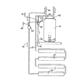
Referring now to Figure 3, there is shown a
baseboard heating system which is fed hot water from a gas-
fired hot water reservoir or furnace 15 through the hot
water circuit 14. The heat exchangers or baseboard heaters
20 are connected in series in the hot water circuit and a
pump 40 circulates the water through the hot water circuit
14 in the direction of arrows 41. The hot water source is
fed city water under pressure through the feed pipe 42 and
the hot water from the tank will exit through the feed pipe
43 whereby to feed the hot water circuit 14. The feed pipe
43 is also provided with a circuit 44 to provide hot water
for domestic use. A thermostat 45 is connected to the pump
40 and to the automatic modulating regulator device 10 to
circulate hot water through the hot water circuit when the
temperature sensed by the thermostat falls below a desired
setting. Of course, there may be more than one thermostat
45 connected to the pump and to the automatic modulating
regulator device depending on the extent of the hot water
circuit and its heat exchangers.
CA 02233279 1998-03-26
Referring now to Figure 4, there is shown a
radiant heating system utilizing the automatic modulating
regulator device 10 of the present invention. The automatic
modulating regulator device is connected in the same manner
as described in Figure 3 with the exception that the hot
water circuit 14 feeds a serpentine array of tubes 50 which
are cast in a concrete slab 51 during the construction of a
building. The hot water circulated therethrough as
indicated by arrows 41 and the automatic modulating
l0 regulator device 10 is connected in the return conduit 52.
the operation is the same as previously described with
reference to Figure 3.
Referring now to Figure 5, there is shown a multi
level residential building application and wherein the heat
source 15 has in its hot water circuit 14 a branch circuit
14' to feed hot water radiators 20' located in a different
dwelling or apartment of a multi-level residential building.
Each of the circuits 14 and 14' are provided with regulating
valves 55 and 55' which are controlled by respective
thermostats 56 and 56' to open or close their respective hot
water circuit 14 or 14' . The valves 55 and 55' as well as
the pump 40 are controlled by a transformer or relay 57
which, when subjected to an electrical power failure, places
the valves 55 and 55' as well as the pump 40 in an open
circuit condition. The transformer or relay device 57 is
also connected to the solenoid actuator 17 of the normally
open valve 11 in the automatic modulating regulator device.
It is within the ambit of the present invention to
cover any obvious modifications of the preferred embodiment
of the present invention as described herein. For example,
the automatic modulating regulator device need not be
coupled together and its main valve components may be
connected to the return conduit at separate locations
whereby to provide the same results. However, it is
preferred for ease of installation that the normally open
valve 11, the self-powered thermostatic valve 18 and the
CA 02233279 1998-03-26
_ g_
flow restrictor be connected together as a unit as shown in
Figure 2A. Those skilled in the art will appreciate that
the conception, upon which this disclosure is based, may
readily be utilized as a basis for the re-designing of other
structures, methods and systems for carrying out the several
purposes of the present invention. It is important,
therefore, that the claims be regarded as including such
equivalent constructions insofar as they do not depart from
the spirit and scope of the present invention.