Note: Descriptions are shown in the official language in which they were submitted.
CA 02233678 1998-04-01
W O 97/13459 PCT~US96/15873
STAMPED CLEVIS FOR ENDOSCOPIC INSTRUMENTS
AND METHOD OF MAKING THE SAME
BACKGROUND OF THE INVENTION
1. Field of the Invention
The invention relates to endoscopic instruments. More
particularly, the invention relates to clevises which are
stamped from a sheet material and progressively formed to obtain
a substantially cylindrical end and at least one clevis arm.
The invention is particularly useful in conjunction with
endoscopic biopsy forceps although it is not limited thereto.
For purposes herein, the term "endoscopic" is to be understood
in its broad sense to include laparoscopic, arthroscopic, and
other microsurgical instruments whether or not used with an
endoscope. In addition, as used herein the term "clevis" means
a member for rotatably coupling at least one end effector to the
distal end of an endoscopic instrument, and not necessarily a U-
shaped member.
2. State of the Art
Endoscopic biopsy forceps are medical instruments which are
used in conjunction with an endoscope for taking tissue samples
from the human body for analysis. As seen in Figures 1-4, a
prior art endoscopic biopsy forceps instrument 10 generally
includes a proximal handle 12, a distal end effector assembly
14, and a long, slender, flexible coil 16. The coil, which is
typically 8 feet long and several millimeters in diameter, has a
pair of axially displaceable control wires 18, 19 extending
therethrough and coupled to the handle 12 and the end effector
assembly 14. The coil 16 is preferably covered with a PTFE, FEP
or polyolefin sheath 15 along substantially all of its length,
and a strain relief sleeve 17 may be provided to cover a
proximal portion of the coil which extends from the handle 12.
The control wires 18, 19 are preferably flexible but
longitudinally inelastic and are ideally formed from 304 steel.
CA 02233678 l998-04-Ol
W O 97/13459 PCT~US96/15873
The proximal handle 12 includes a central shaft 20 and a
displaceable spool 22. The proximal end of the shaft 20 is
provided with a thumb ring 24 and a longitudinal bore 26 is
provided at the distal end of the shaft 20. A longitudinal slot
28 extends from the proximal end of bore 26 to a point distal of
the thumb ring 24. The displaceable spool 22 is provided with a
cross member 30 which passes through the slot 28 in the central
shaft 20. The cross member 30 is provided with a coupling means
32 for attaching the proximal ends of the control wires 18, 19.
The end effector assembly 14 includes a clevis 34 which is
coupled to the distal end of the coil 16, and a pair of forceps
jaws 36, 38. The clevis 34 has a pair of clevis arms 34a, 34b
between which the jaws 36, 38 are rotatably mounted on an axle
pin 40. Each jaw 36, 38 is provided with a distal cutting edge
36a, 38a, a proximal tang 36b, 38b, and a mounting hole 36c, 38c
therebetween. The proximal tangs 36b, 38b are each coupled to
the distal end of a respective control wire 18, 19. From the
foregoing, those skilled in the art will appreciate that
relative movement of the shaft 20 and spool 22 results in
movement of the control wires 18, 19 relative to the coil 16.
Such action results in opening and closing of the jaws 36, 38.
Optionally, as shown in Figure 3, an end effector assembly 14'
may also include a flat knife or spike which is mounted between
the jaws 36, 38.
As seen best in Figure 4, the tang of each jaw is offset
from the centerline CL of the jaw cup, thereby permitting the
jaw 36 to be substantially identical to jaw 38. The clevis 34
is typically formed as a unitary molded or cast member and has a
substantially cylindrical proximal end 34c from which the clevis
arms 34a, 34b extend. The proximal end 34c of the clevis 34 is
crimped or welded to the distal end of the coil 16.
The endoscopic biopsy procedure is accomplished through an
endoscope which is inserted into a body and guided by
CA 02233678 1998-04-Ol
W O 97/13459 PCTrUS96/15873
manipulation to the biopsy site. The endoscope typically
includes a long narrow flexible tube with an optical lens and a
narrow lumen for receiving a biopsy forceps. The practitioner
guides the endoscope to the biopsy site while looking through
the optical lens and inserts the biopsy forceps through the
lumen of the endoscope to the biopsy site. While viewing the
biopsy site through the optical lens of the endoscope, the
practitioner manipulates the actuating handle to effect a tissue
sampling operation at the distal end of the instrument. After a
sample has been obtained, the practitioner and/or an assistant
carefully withdraws the instrument from the endoscope while
holding the actuating handle to maintain the jaws in a closed
position.
It is understood that in order to be effective in obtaining
a biopsy sample, the cutting edge of the forceps jaws should be
very sharp. Moreover, the entire end effector assembly should
be relatively durable since it may be necessary to apply
considerable force to the end effector assembly in order to
obtain a biopsy sample. However, due to the small size of the
end effector assembly (typically a few millimeters in diameter),
durable components are expensive to manufacture. The presently
preferred method of making a clevis and end effectors is by
investment casting of bronze or other suitable material,
although other methods such as molding and ma~h; n; ng are also
known in the art.
SUMMARY OF THE INVENTION
It is therefore an object of the invention to provide a
durable clevis for use in an endoscopic biopsy forceps
instrument.
It is also an object of the invention to provide a durable
clevis which is inexpensive to manufacture.
.
-
CA 02233678 1998-04-01
W O 97/13459 PCTrUS9611S873
It is another object of the invention to provide a method
of making an inexpensive yet durable clevis for use in an
endoscopic biopsy forceps instrument.
In accord with these objects which will be discussed in
detail below, the stamped clevis of the present invention is
preferably made from a stainless steel sheet which is cut
(stamped) to form at least one relatively narrow distally
extending arm and at least one relatively broad proximal base.
The distal arm is provided with at least one mounting hole for
receiving an axle pin and the proximal portion is wrapped to
form a cylinder or a broken cylinder. According to a presently
preferred first embodiment of the invention, a stainless steel
sheet is cut to form two relatively broad proximal bases and two
relatively narrow substantially parallel distal arms, one arm
extending from each base. The distal end of each arm is
provided with a mounting hole and the arms are joined by a
substantially orthogonal cross member proximal of the mounting
holes. Preferably, a central tab extends distally from the
cross member and is provided with a third mounting hole. The
cut sheet is formed by bending the cross member on either side
of the central tab in an "S" configuration so that the mounting
holes are aligned substantially coaxially. The two proximal
bases are bent towards each other to form a bifurcated cylinder.
The bifurcated cylinder can be crimped or welded to the distal
end of a coil and tangs of jaws can be mounted between the
central tab and a respective arm on an axle pin which passes
through the three holes. In an alternative first embodiment of
the invention, the steel sheet is cut so that a distal spike
extends from the central tab.
According to a second embodiment of the invention, a
stainless steel sheet is cut to form a single central tab with a
distally extending spike and a pair of relatively broad proximal
bases. The bases are bent in opposite directions to form a
substantially cylindrical member having an "S-shaped" section
CA 02233678 1998-04-01
W O 97/13459 PCTrUS96/15873
adjacent to the central tab. The central tab is provided with a
single mounting hole for receiving an axle pin so that jaws may
be mounted on either side of the tab with the spike extending
between the jaws. The proximal cylindrical portion may be
crimped or welded to the distal end of a coil.
According to a third embodiment of the invention, a
stainless steel sheet is cut to form two substantially parallel
distal arms extending from a single base. Each arm is provided
with a distal mounting hole. The base is wrapped to form a
cylinder or a broken cylinder with the arms parallel and the
mounting holes substantially coaxial. A pair of jaws can be
mounted between the distal arms and the proximal cylinder can be
crimped or welded to the distal end of a coil.
Additional objects and advantages of the invention will
become apparent to those skilled in the art upon reference to
the detailed description taken in conjunction with the provided
figures.
BRIEF DESCRIPTION OF THE DRAWINGS
Figure 1 is an enlarged broken side elevation view in
partial section of the proximal end of a prior art biopsy
forceps instrument;
Figure 2 is an enlarged broken side elevation view in
partial section of the distal end of a prior art biopsy forceps
instrument;
Figure 3 is a view similar to Figure 2 of the distal end of
a prior art biopsy forceps instrument incorporating a spike
between the forceps jaws;
Figure 4 is an enlarged top plan view in partial section of
the distal end of a prior art biopsy forceps instrument;
CA 02233678 l998-04-Ol
W O 97/13459 PCT~US96/15873
Figure 5 is an enlarged plan view of a first embodiment of
a stamped clevis according to the invention prior to forming;
Figure 6 is an enlarged perspective view of the clevis of
Figure 5 after forming;
Figure 6a is an enlarged partially transparent top view in
partial section of the clevis from Figures 5 and 6 as part of
the distal end of a biopsy forceps instrument;
Figure 7 is an enlarged plan view of an alternate first
embodiment of a stamped clevis according tot he invention prior
to forming;
Figure 8 is a sectional view taken along line 8-8 of Figure
7;
Figure 9 is an enlarged perspective view of the clevis of
Figure 7 after forming;
Figure 10 is an enlarged plan view of a second embodiment
of a stamped clevis according to the invention prior to forming;
Figure 11 is an enlarged top plan view of the clevis of
Figure 10 after forming;
Figure 12 is an enlarged plan view of a third embodiment of
a stamped clevis according to the invention prior to forming;
and
Figure 13 is an enlarged perspective view of the clevis of
Figure 12 after forming.
CA 02233678 1998-04-01
W O 97/13459 PCTrUS96/15873
DETATT~F~n DESCRIPTION OF THE PREFERRED EMBODIMENTS
Referring now to Figures 5, 6, and 6a, a first embodiment a
stamped clevis 100 according to the invention is made from a
stainless steel sheet preferably approximately .007 inches thick
and cut to the pattern shown in Figure 5. More particularly,
the sheet is cut to form two relatively broad proximal bases
102, 104 and two relatively narrow substantially parallel distal
arms 106, 108, one arm extending from each base. The distal end
of each arm is provided with a mounting hole 110, 112 and the
arms are joined by a substantially orthogonal cross member 114
proximal of the mounting holes. The cross member 114 is
preferably provided with a central tab 116 which extends
distally from the cross member and is provided with a third
mounting hole 118. The stamped clevis 100 is then formed by
bending the cross member 114 on either side of the central tab
116 in an "S" configuration so that the mounting holes 110, 112,
and 118 are aligned substantially coaxially. The two proximal
bases 102, 104 are bent towards each other to form a bifurcated
cylinder having a proximal opening 119 and slits 121, 123. The
bifurcated cylinder can be crimped or welded to the distal end
of a coil 16 as shown in Figure 6a, and the tangs 36b, 38b of
jaws 36, 38 can be mounted between the central tab 116 and a
respective arm 106, 108. As shown in Figure 6, the formed
clevis 100 has an overall length of approximately 0.3 inches and
the bifurcated cylinder formed by the bases 102, 104 has an
overall diameter of approximately 0.09 inches. According to a
preferred aspect of this embodiment, the arms 106, 108 are bent
inward at an angle of approximately 15~ along a portion 106a,
108a just proximal of the mounting holes 110, 112.
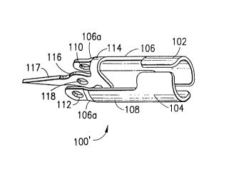
An alternate first embodiment of a stamped clevis 100' is
shown in Figures 7 through 9. This embodiment of the invention
is substantially identical to the first embodiment with
identical reference numerals referring to identical features.
The difference between this embodiment and the first embodiment
CA 02233678 l998-04-Ol
W O97/13459 PCTrUS96/lS873
is a spike 117 which is formed on the central tab 116 and
extends distally therefrom for a distance of approximately .135
inches from the center of the hole 118. In order to provide the
spike 117 with a relatively sharp knife-like quality, a zone "z"
in the center of the cross member 114 is coined on both sides
with a smooth taper to a thickness of approximately .005 inches.
The clevis 100' is formed in the same manner as the clevis 100
to the shape shown in Figure 9.
According to a second embodiment of the invention, shown in
Figures 10 and 11, a clevis 200 is formed from a stainless steel
sheet which is cut to form a pair of relatively broad proximal
bases 202, 204 with a single central tab 216 having a distally
extending spike 217 and a mounting hole 218. The bases 202, 204
are preferably provided with angled distal edges 202a, 204a
which ramp proximally away from the central tab 216. The clevis
200 is formed by bending the bases 202, 204 in opposite
directions to form a substantially cylindrical member having an
"S-shaped" section adjacent to the central tab 216. When formed
into a cylindrical member, the angled distal edges 202a, 204a
form distal spiral sections which provide room for the movement
of tangs of jaws coupled to the central tab 216. Those skilled
in the art will appreciate that in order to assure sufficient
strength, in this embodiment of the clevis, the mounting hole
must be located relatively close to the cylindrical portion.
Therefore, in order to provide room for jaw tangs, portions of
the cylindrical portion must be cut back as shown. The proximal
cylindrical portion may be crimped or welded to the distal end
of a coil.
According to a third embodiment of the invention, shown in
Figures 12 and 13, a clevis 300 is formed from a stainless steel
sheet which is cut to form a single base 302 with two
substantially parallel distal arms 306, 308 extending therefrom.
Each arm is provided with a distal mounting hole 310, 312. The
base 302 is wrapped to form a cylinder or a broken cylinder with
CA 02233678 1998-04-01
W O 97/13459 PCT~US96/15873
the arms 306, 306 parallel and the mounting holes 310, 312
substantially coaxial. A pair of jaws can be mounted between
the distal arms and the proximal cylinder can be crimped or
welded to the distal end of a coil.
There have been described and illustrated herein several
embodiments of a stamped clevis for an endoscopic instrument and
methods of making the same. While particular embodiments of the
invention have been described, it is not intended that the
invention be limited thereto, as it is intended that the
invention be as broad in scope as the art will allow and that
the specification be read likewise. Thus, while particular
~lmengionS and materials have been disclosed, it will be
appreciated that other ~lm~nsions and materials could be
utilized. Also, while cylindrical portions have been shown as
incomplete or broken cylinders, it will be recognized that
welding, soldering, brazing, or other operations may be used to
complete the cylindrical portions if desired. Further, while
the clevis was shown with respect to use in a biopsy forceps
instrument, it will be appreciated that the clevis could be used
as part of an endoscopic clamp, scissors, dissectors, etc., and
that the proximal cylindrical end of the clevis can be coupled
to a hollow tube or a flexible coil. Moreover, while particular
configurations have been disclosed in reference to the mounting
holes and the spike, it will be appreciated that other
configurations could be used as well. It will therefore be
appreciated by those skilled in the art that yet other
modifications could be made to the provided invention without
deviating from its spirit and scope as so claimed.