Note: Descriptions are shown in the official language in which they were submitted.
CA 0223374~ 1998-04-02
Docket No.: HENS-0013
ROTARY LOCK SYSTEM FOR EXCAVATING TOOTH/ADAPTER ASSEMBLY
BACKGROUND OF THE INVENTION
The present invention generally relates to material
displacement apparatus and, in a preferred embodiment
thereof, more particularly relates to a specially designed
rotary lock structure for releasably holding a replaceable
earth excavating tooth point on a nose portion of an
associated adapter structure.
A variety of types of material displacement apparatus,
such as earth working structures, are typically provided
with replaceable portions that are removably carried by
larger base structures and come into abrasive wearing
contact with the material being displaced. For example,
excavating tooth assemblies provided on digging such as
excavating buckets or the like typically comprise a
relatively massive adapter portion which is suitably
anchored to the forward bucket lip and has a reduced cross-
section, forwardly projecting nose portion, and a
replaceable tooth point having formed through a rear end
thereof a pocket opening that releasably receives the
adapter nose. The removability of the tooth point
advantageously permits the more massive adapter to have a
substantially longer operating life than if the point was
an integral portion thereof.
To captively retain the tooth point on the adapter
nose, aligned transverse openings are formed through these
interengageable elements adjacent the rear end of the
CA 0223374~ 1998-04-02
point, and a suitable connector structure is forcibly
driven into and retained within the openings to releasably
anchor the replaceable tooth point on its associated
adapter nose portion. These connector structures adapted
to be driven into the aligned tooth point and adapter nose
openings typically come in two primary forms - (1) wedge
and spool connector sets, and (2) flex pin connectors.
A wedge and spool connector set comprises a tapered
spool portion which is initially placed in the aligned
tooth and adapter openings, and a tapered wedge portion
which is subsequently driven into the openings, against he
spool portion, to jam the structure in place within the
openings in a manner exerting high rigid retention forces
on he interior opening surfaces and press the nose portion
into a tight fitting engagement with the interior surface
of the tooth socket.
Very high drive-in and knock-out forces are required
to insert and later remove the steel wedge and typically
require a two man effort to pound the wedge in and out -
one man holding a removal tool against an end of the wedge,
and the other man pounding on the removal tool with a
sledge hammer. The drive-in and knock-out forces, of
course, increase with the size of the tooth/adapter nose
assembly involved. This creates a safety hazard due to the
possibility of flying metal slivers and/or the second man
hitting the first man instead of the removal tool with the
sledge hammer. Additionally, wear between the
tooth/adapter nose assembly surface interface during
excavation use of the tooth tends to loosen the original
tight fit of the wedge/spool structure within the tooth and
adapter nose openings, thereby permitting the wedge/spool
structure to fall out of the openings and thus permitting
the tooth to fall off the adapter nose.
Flex pin connector structures, on the other hand,
typically comprise two elongated metal members held in a
CA 0223374~ 1998-04-02
spaced apart, side-by-side orientation by an elastomeric
material bonded therebetween. The flex pin structure must
be longitudinally driven into the tooth and adapter nose
openings to cause the elastomeric material to be compressed
and resiliently force the metal members against the nose
and tooth opening surfaces to retain the connector
structure in place within the openings and resiliently
press the adapter nose portion into tight fitting
engagement with the interior surface of the tooth socket.
This creates essentially the same potential safety hazards
as arise when a metal wedge member is being driven into the
tooth and adapter nose openings as previously described
herein. Subsequently, of course, the flex pin structure
must be pounded out of the tooth and adapter openings.
Conventionally constructed flex pin structures also
have other disadvantages and limitations. For example,
compared to wedge/spool structures they have a
substantially lower in-place retention force. This is due
to the fact that the elastomeric flex pin portion, as the
flex pin is being driven into place within the
tooth/adapter nose assembly, must be compressed more than
when it reaches its installed position within the assembly.
Thus, the elastomeric element partially "relaxes" when it
reaches its installed position and cannot exert its full
available resilient retention force on the tooth and
adapter nose surfaces.
Moreover, in conventionally configured flex pin
structures, the retention of the flex pin structure within
the tooth/adapter nose assembly is dependent upon
maintaining a certain minimum resilient force by the
elastomeric element on an interior surface portion of the
tooth/adapter nose assembly. When internal assembly
surface wear progresses to a certain point the connector
can fall out because this resilient force is no longer
large enough. It can be seen from the foregoing that it
CA 0223374~ 1998-04-02
would be desirable to provide improved excavating tooth
connector apparatus that eliminates or at least
substantially reduces the above-mentioned problems,
limitations and disadvantages commonly associated with
conventional excavating tooth and other material
displacement equipment connector apparatus of the general
type described above. It is accordingly an object of the
present invention to provide such improved connector
apparatus.
SU~ARY OF THE INVENTION
In carrying out principles of the present invention,
in accordance with a preferred embodiment thereof, improved
earth working tooth and adapter apparatus is provided for
use on an earth working structure such as an excavating
bucket. The improved apparatus includes a replaceable
tooth point having a pocket area, an outer wall, and a
first opening extending through the outer wall into the
pocket area and having a side surface; and an adapter
having a forwardly projecting nose portion with a second
opening extending therethrough and having a side surface,
the nose portion being removably insertable into the tooth
point pocket area in a manner causing the second opening to
underlie the first opening in the tooth point.
To releasably retain the replaceable tooth point on
the adapter nose, a specially designed rotary lock
structure is provided. The lock structure has a
resiliently deflectable force exerting portion and, with
the nose portion inserted into the tooth point pocket area,
is insertable along an insertion axis into the first and
second openings in a first rotational orientation and then
rotated about the insertion axis to a second rotational
orientation.
According to a key feature of the invention, the side
CA 0223374~ 1998-04-02
surfaces of the first and second openings are configured to
resiliently deflect the force exerting member, in a manner
causing the rotary lock structure to exert on the adapter
nose portion and the tooth point a resilient force tending
to tighten the tooth point rearwardly onto the nose
portion, in response to movement of the rotary lock
structure from its first rotational orientation to its
second rotational orientation within the first and second
openings.
In its preferred embodiment, the rotary lock structure
includes a generally cylindrical body portion having a side
surface recess formed therein, a force exerting member
movably received in the side surface recess, and first
resilient means for resiliently biasing the force exerting
member outwardly through the side surface recess. An
opening extends radially through the body portion and
movably receives a detent member movably received in the
opening. Second resilient means are provided for
resiliently biasing the detent member outwardly through the
opening.
The earth working tooth and adapter apparatus also
preferably includes structure associated with the adapter
nose for cooperating with the detent member to releasably
prevent the inserted rotary lock structure from rotating
from its second rotational orientation back to its first
rotational orientation. Representatively, such structure
includes a depression formed in the adapter nose and having
a ramped surface adjacent a detent pocket formed in the
adapter nose. As the inserted lock structure is rotated
from its first rotational orientation to its second
rotational orientation the ramped surface inwardly cams the
detent member into its associated lock structure body
opening, and then permits the retracted detent member to
snap outwardly into the adapter nose detent pocket.
In one embodiment of the tooth and adapter apparatus
CA 0223374~ 1998-04-02
the detent member is of a shearable construction and may be
broken, to permit removal of the installed rotary lock
structure, by forcibly moving the lock structure relative
to the balance of the apparatus. In other embodiments of
the tooth and adapter apparatus the adapter nose detent
pocket is provided with sloping side surfaces which cams
the detent member out of the detent pocket when the
installed lock structure is forcibly driven axially or
rotationally relative to the balance of the tooth and
adapter apparatus.
BRIEF DESCRIPTION OF THE DRAWINGS
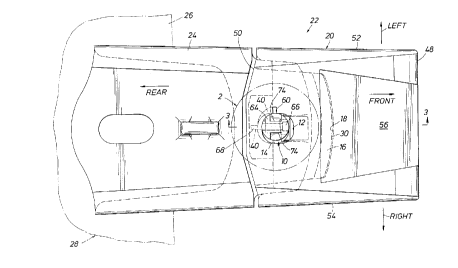
FIG. 1 is a top side view of an earth working
excavating tooth/adapter assembly in which a replaceable
tooth point is removably held in place on an adapter nose
portion using a specially designed rotary lock system
embodying principles of the present invention;
FIG. 2 is an enlargement a portion of the dashed
circle area "2" in FIG. 1;
FIG. 3 is an enlarged scale, somewhat simplified
cross-sectional view through the assembly taken along line
3-3 of FIG. 1;
FIG. 4 is a reduced scale top side view of the adapter
with the tooth point removed therefrom;
FIG. 4A is an enlargement of the dashed circle area
"4A" in FIG. 4;
FIG. 5 is a reduced scale top side view of the tooth
point removed from the adapter nose;
FIG. 6 is an enlarged scale side elevational view of
a rotary lock structure removed from the assembly;
FIG. 7 is an exploded perspective view of the rotary
lock structure;
FIG. 8 is a top side view of the excavating
tooth/adapter assembly prior to a rotational tightening of
CA 0223374~ 1998-04-02
the rotary lock structure therein;
FIG. 9 is an enlargement of a portion of the dashed
circle area "9" in FIG. 8; and
FIGS. 10 and 11 are schematic partial cross-sectional
views through alternate embodiments of the excavating
tooth/adapter assembly respectively illustrating the inward
release camming of a detent pin portion of the installed
rotary lock structure in response to axial and rotational
driving of the lock structure relative to the balance of
the assembly.
DETAILED DESCRIPTION
Referring initially to FIGS. 1, 3, 4 and 5, the
present invention provides a specially designed rotary lock
structure 10 which is extended into generally aligned tooth
and adapter nose openings 12,14 to releasably retain an
adapter nose portion 16 within the tapered socket 18 of a
replaceable excavating tooth point 20 in a tooth/adapter
assembly 22. The adapter nose 16 is a forwardly projecting
portion of a larger adapter body 24 secured to a portion of
an earth working structure such as, for example, the lower
front edge portion 26 of the excavating bucket 28 partially
illustrated in phantom in FIG. 1.
Turning now to FIGS. 1 and 3-4A, the adapter nose 16
has a front end 30, opposite top and bottom sides 32 and 34
between which the opening 14 extends, and opposite left and
right sides 36 and 38. Representatively, as best
illustrated in FIG. 4A, the adapter nose opening 14 has an
arcuate but noncircular configuration, being of a generally
ovoid shape with somewhat flattened opposite left and right
side surface portions 16a,16b and somewhat flattened
opposite front and rear side surface portions 16c,16d.
For purposes later described herein, a depression 40
is formed in the top side 32 of the adapter nose 16
~ ~ CA 0223374~ l998-04-02
adjacent the periphery of the opening 16 and extending
through a circumferential arc of approximately ninety
degrees. The depression 40 has an outer side wall portion
42 which is circumferentially ramped relative to the
opening 16, progressively sloping radially inwardly in a
counterclockwise direction as viewed in FIG. 4A. The
radially innermost end of the outer side wall portion 42 iS
adjacent a radially outwardly extending, generally
rectangular pocket portion 44 of the depression 40, while
at the radially outermost end of the wall 42 iS a generally
rectangular entry portion 46 of the depression 40.
Tooth point 20, as best illustrated in FIGS. 1, 3 and
5, has a front end 48, a rear end 50 through which the
pocket area 18 rearwardly opens, opposite left and right
side walls 52 and 54, and opposite top and bottom side
walls 56 and 58 through which the opening 12 extends into
the interior of the pocket area 18. For purposes later
described herein, the portion of the opening 12 that
extends inwardly through the top side wall 56 has a
generally rectangular radially outwardly extending portion
60. When the adapter nose 16 iS received in the tooth
pocket 18 the radially outwardly extending tooth opening
portion 60 directly overlies the entry portion 46 of the
adapter nose top side wall recess 40 (see FIG. 8). Formed
in the inner side surface of the top wall 54 iS an arcuate
recess 62 (see FIGS. 3 and 5) which, with the adapter nose
16 received in the tooth point pocket 18, generally
overlies the adapter nose recess 40 and forms an upward
extension thereof.
With reference now to FIGS. 6 and 7, the rotary lock
structure 10 includes (1) a cylindrical metal body 64, (2)
an elongated rectangular metal force exerting member 66,
and (3) a cylindrical metal detent member 68. Body 64 has
oppositely sloping upper and lower end surfaces 70 and 72,
a diametrically opposite pair of radially inwardly
CA 0223374~ l998-04-02
extending side surfaces recesses 74 at its upper end, and
an axially elongated rectangular side surface recess 76
positioned below and circumferentially between the upper
end recesses and configured to slidingly receive the force
exerting member 66 as later described herein.
The force exerting member 66 has three longitudinally
spaced, counter-sunk circular bores 78 extending
therethrough and configured to slidingly receive three
elongated cap screws 8 O. Screws 8 0 extend through three
coil spring members 82 which underlie the force exerting
member 66 and are positioned within the recess 76. As best
illustrated in FIG. 6, the springs 82 bear at their outer
ends against the underside 84 of the force exerting member
66, with inner end portions of the springs 82 being
received in countersunk circular bores 86 which extend
inwardly through the inner side surface of the body side
surface recess 76. The inner ends of the screws 80 are
threaded into the reduced diameter inner end portions of
the bores 86 as illustrated in FIG. 6.
Accordingly, the force exerting member 66 iS
resiliently biased outwardly through the side surface
recess 76 to its relaxed position shown in FIG. 6 by the
springs 82. To provide such outward biasing another type
of resilient structure, such as an elastomeric material,
could be used in place of the springs 82. Upon receiving
a laterally inwardly directed force, the member 66 iS
displaced into the recess 76, against the resilient
resistance force of the springs 82, as indicated by the
arrow 88 in FIG. 6.
A circular bore 90 extends transversely through an
upper end portion of the lock structure body 64, between
its upper end recesses 74, and has an enlarged, threaded
outer end portion 90a on the same side of the body as the
recess 76, and a countersunk inner end portion 90b on the
side of the body 64 opposite from the recess 76. The
~ CA 0223374~ l998-04-02
cylindrical detent member 68 has a chamfered outer end 92,
and a radially enlarged outer end 94, extends through a
resilient O-ring seal member 96, is slidably received in
the bore 90, and projects outwardly through the inner end
of the bore 90 (see FIG. 6) with the enlarged inner end 94
of the detent member 68 preventing the detent member 68
from passing outwardly through the counterbored inner end
9Ob of the bore 90.
A tubular spring guide member 98 iS coaxially received
within the bore 90 and has a threaded plug member 100
threaded into its outer end and also threaded into the
enlarged outer end portion 90a of the bore 90. An
elongated coiled compression spring member 102 is received
within the spring guide member 98. Spring 102 bears at one
end against the inner end of the plug member 100, and at
its other end against the enlarged detent member end
portion 94, and resiliently biases the detent member 68 to
its radially outwardly extended normal position shown in
FIG. 6. A radially inwardly directed force on the detent
member 6 8 moves the detent member 6 8 inwardly into the bore
90, against the resilient resistance force of the spring
102, as indicated by the arrow 104 in FIG. 6.
Turning now to FIGS. 8 and 9, to removably install the
tooth point 20 on the adapter nose 16, the nose 16 iS first
inserted forwardly into the pocket area 18 of the tooth
point 20 in a manner bringing the portion of the tooth
opening 12 in the top tooth wall 56 into an overlying
relationship with the adapter nose opening 14 as may be
best seen in FIG. 9. It should be noted that, with the
tooth 20 placed on the adapter nose 16 in this manner, the
tooth and adapter nose openings 12,14 are relatively
configured and arranged in a manner such that they are
generally aligned in a left-to-right direction, but are
laterally offset from one another in a front-to-rear
direction.
-10 -
- CA 0223374~ 1998-04-02
More specifically, a rear side surface portion of the
tooth opening 12 is forwardly offset from a corresponding
rear side surface portion of the underlying adapter nose
opening 14, and a front side surface portion of the tooth
opening 12 is forwardly offset from a corresponding front
side surface portion of the underlying adapter nose opening
14. The somewhat ovoid tooth opening 12 is preferably
elongated in a front-to-rear direction so that the front-
to-rear offset between the corresponding front side surface
portions of the openings 12,14 is greater than the front-
to-rear offset between their corresponding rear side
surface portions. This provides a built-in tolerance that
keeps the front side surface portion of the tooth point
opening 12 from interfering with lock structure
installation when the tooth moves further back on the
adapter nose due to wear on the adapter nose.
Additionally, as can be best seen in FIG. 9, the distance
between the aligned left and right side surface portions of
the openings 12,14 is greater than the front-to-rear
distance between the rear side surface portion of the tooth
opening 12 and the front side surface portion of the
adapter nose opening 14. The distance between the aligned
left and right side surface portions of the openings 12,14
defines in the combined opening means 12,14 a minimum lock
structure insertion width which extends generally
transversely to the insertion axis and to the front-to-rear
direction of the assembly 22.
Still referring to FIGS. 8 and 9, with the tooth point
20 positioned on the adapter nose 16 as shown, the
previously described rotary lock structure 10 is installed
in the tooth and adapter nose openings 12,14 as follows.
With its top end up and its outwardly projecting detent
member 68 facing leftwardly as viewed in FIGS. 8 and 9, the
rotary lock structure body 64 is axially inserted
downwardly into the openings 12,14 (along an insertion axis
- CA 0223374S l998-04-02
which is the longitudinal axis of the body 64) SO that the
detent member 68 passes downwardly through the radially
outwardly projecting portion 60 of the tooth opening 12 and
enters the underlying adapter nose top side recess portion
46 (see FIG. 4A) and the outwardly projecting force
exerting member portion 66 of the inserted rotary lock
structure 10 is contiguous with the right side surface
portion of the adapter nose opening 14.
Next, using an appropriate torquing tool (not shown)
having portions inserted into the upper end recesses 74 of
the lock body 64, the inserted lock structure 10 is
forcibly rotated in a counterclockwise direction from its
initially inserted position shown in FIGS. 8 and 9 through
ninety degrees relative to the balance of the assembly 22
to its finally installed position shown in FIGS. 1 and 2.
During such forcible rotation of the inserted lock
structure two things occur.
First, as the lock structure 10 is rotated, because of
the relative positions and configurations of the openings
12 and 14, the initially outwardly projecting force
exerting member 66 (see FIG. 9) is brought into engagement
with the front side surface portion of the adapter nose
opening 14 which serves to rearwardly push the force
- exerting member 66 into the lock structure body side recess
76, against the resilient resistance force of the force
exerting member springs 82 (see FIGS. 6 and 7). In turn,
as illustrated in-FIGS. 1 and 2, this forces a now rear
side portion of the lock structure body 64 into engagement
with a facing rear side surface portion of the tooth point
opening 12, thereby causing the installed rotary lock
structure 10 to exert on the tooth point 20 a continuous
resilient force on the tooth point 20 tending to rearwardly
tighten it onto the adapter nose.
Second, as the lock structure 10 is rotated, the outer
end of the outwardly projecting detent member 68 iS slid
CA 0223374~ 1998-04-02
along the circumferentially ramped adapter nose recess side
surface 42 to thereby progressively cam the detent member
68 into the lock structure body bore 90 (see FIG. 6),
against the resilient resistance of the detent spring 102,
until the detent member circumferentially reaches the
adapter nose pocket area 44 at which point the detent
member 68 snaps into the pocket area 44 (see FIGS. 1 and
2). This releasably prevents the installed rotary lock
structure 10 from rotating back to its initially inserted
position (see FIGS. 8 and 9) which, until lock structure
removal is intended, would undesirably permit the force
exerting member to return to its outwardly projecting
relaxed position and thus permit the lock structure 10 to
fall out of the tooth and adapter nose openings 12 and 14
and the tooth 20 to fall of the adapter nose 16.
To facilitate removal of the installed rotary lock
structure 10, and thereby permit removal and replacement of
the tooth point 20, the detent member 68 is preferably of
a frangible or shearable construction. As schematically
illustrated in FIG. 3, this permits the lock structure body
64 to be axially driven, as indicated by the double-ended
arrow 103, relative to the balance of the assembly 22 (with
a relatively small force) to shear the detent pin 68
against a generally horizontal vertically facing side
surface of the pocket area 44 and permit removal rotation
and axial withdrawal of the installed rotary lock structure
10 .
FIGS. 10 and 11, respectively, schematically depict
interior cross-sectional portions of alternate embodiments
22a and 22b of the previously described excavating
tooth/adapter assembly 22. In the alternate assembly 22a
(FIG. 10), the lock structure detent member 68a has sloping
side surfaces which face similarly sloped vertically facing
side surfaces of the adapter nose depression 44a which
receives the detent member 68a. With this detent
-13-
- ~ CA 0223374~ 1998-04-02
member/detent pocket configuration the installed lock
structure lOa may be axially driven upwardly or downwardly,
as indicated by the arrows 108 in FIG. 10 to cause the
sloped vertically facing surfaces of the pocket 44a to cam
the detent member 68a inwardly (as indicated by the arrow
110) and permit removal rotation and axial withdrawal of
the lock structure lOa. In the alternate assembly
embodiment lOb (FIG. 11), the detent member 68b also has
sloping side surfaces, and the opposite horizontally facing
side surfaces of the adapter nose pocket 44b are similarly
sloped. This permits the body 64b of the installed lock
structure lOb to be forcibly rotated, as indicated by the
arrow 112, to thereby cause the sloped, horizontally facing
side surfaces of the adapter nose pocket 44b to inwardly
cam the detent member 64b, as indicated by the arrow 114
and permit the lock structure lOb to then be axially
removed from the balance of the assembly 22b.
As can be readily seen from the foregoing, the rotary
lock structure 10 provides a variety of advantages over
conventional connector structures which have been used in
the past to removably hold a tooth point on its associated
adapter nose portion. For example, there is no need to
drive the lock structure 10 into the tooth and adapter nose
openings 12 and 14 to compress the laterally resilient
portion of the lock structure. Instead, due to the unique
arrangement and configuration of the tooth/adapter opening
means 12,14 the lock structure 10 may be simply slipped
into the assembly 22 and subsequently rotated (with no
pounding force) to exert and maintain the resilient
tightening force on the tooth 20.
Additionally, since the force exerting member 66 does
not have to be depressed and then caused to snap into a
recess during installation of the lock structure, all of
the available resilient force associated with the force
exerting member 66 may be used to maintain a resilient
-14-
- CA 0223374~ 1998-04-02
tightening force on the tooth 20. Furthermore, the
resiliently biased force exerting member 66 desirably
compensates for operating wear along the adapter nose/tooth
pocket surface interface by automatically moving the tooth
20 further rearwardly along the adapter nose 16 in response
to such wear. Moreover, retention of the locking structure
10 within the tooth and adapter nose openings 12,14 is not
dependent upon the maintenance of a resilient spring force
on the force exerting member 66. Instead, the locking
structure 10 is provided with an independent structure in
the form of the separate detent member 68.
The foregoing detailed description is to be clearly
understood as being given by way of illustration and
example only, the spirit and scope of the present invention
being limited solely by the appended claims.