Note: Descriptions are shown in the official language in which they were submitted.
CA 02233912 1998-04-02
SPECIFICATION
TITLE OF THE INVENTION
HEAT COOKER
BACK~ROUND OF THE INVENTION
1. FIELD OF THE INVENTION
The present invention relates to a heat cooker. More
particularly, the present invention relates to an accessory storage
section disposed in a heat cooker.
2. RELATED ARTS
Aheatcookergenerallycomprisesabox-likecookerbodyhaving
ventholes at its bottom board, a heating room disposed in the cooker
body and a heat source disposed in the cooker body for heating foods
intheheatingroom. Theheatsourcemayemployamicrowavegenerator,
an electric heater and/or t-he like.
In the case of cooking by using a heat cooker, accessories
are used which are provided Ls an addendum to the heat cooke~, e.g.,
an oven plate, a gridiron, a recipe book, a heat insulation mitten,
a handle for taking the oven plate out and the like depending on
the needs. These accessories may include ones which are rarely used
by a cook depending on how the cooker is used. Then, it is not easy
to secure enough space for storing such accessories. Additionally,
there is a problem such that it is not easy to take accessories out
when it is necessary if these are once stored.
In order to solve thisproblem, a heat cooker with anaccessory
CA 02233912 1998-04-02
stor,~ge section at the bottom part thereof is disclosed, e.g., in
Japanese Unexamined Utility Model Publications Nos. SHO
55(1980)-3213 and SHO 57(1982)-119209.
However, the above-mentioned storage section is used for
inserting accessories into a storage space at the bottom part of
the cooker. Therefore, it is very inconvenient for taking
accessories in and out. Moreover, small accessories tend to be put
in an innermost part, as if they were missing, so that there is a
fear that they become useless because they cannot be found when they
are needed.
Moreover, there is a fear that the accessories block ventholes
formed on the bottom part of the heat cooker, so that it prevents
discharge of heat from cont:rol devices of the heat cooker.
Thepurposeofthepresentinventionistoprovideaheatcooker
equipped with an accessory storage section without preventing
discharge of heat from the inside of the cooker body.
SUM~RY OF THE INVENTION
Thus, the present invention provides a heat cooker comprising
a generally box-like cooker body having ventholes at a bottom board
thereof, a heating room disposed in the cooker body, a heat source
disposed in the cooker body for heating foods in the heating room
and ~n accessory storage section disposed under the bottom board
of the cooker body, wherein the accessory storage section comprises
a pair of leg bodies which support the cooker body and are attached
on both sides of the bottom board and a plate-like accessory storage
body which is supported by t:he leg bodies and inserted between the
leg bodies to be capable of being pulled out forward, and wherein
the :Leg bodies are further provided with ventilation slits forming
CA 02233912 1998-04-02
an airwaybetween an inside of the cooker body and an outside through
the ventholes of the bottom board and an area above the plate-like
acce,sory storage body.
According to the present invention, cooling of the inside of
thecookerbodyisnotprevent:edeveniftheaccessorystoragesection
includingastructure forinsertingtheplate-likeaccessorystorage
body between the leg bodies is disposed under the bottom board of
the cooker body, because tht leg bodies constituting the accessory
storage section are provided with ventilation slits that form an
airway between the inside of the cooker body and the outside through
the ventholes of the bottom board of the cooker body and an area
above the plate-like body.
The heat source to be used in the present invention may employ
microwave heating by a magnetron, heater heating by a heater or the
like.
Examples of accessories in the present invention include an
oven plate, a gridiron, a recipe book, a heat insulation mitten and
a handle for taking the oven plate out.
Theventilationslits inthepresentinvention areconstructed
so a, to form an airway between an inside of the cooker body and
an outside through the ventholes of the bottom board and an area
above the plate-like accessory storage body. In disposing the
ventilation slits, it is necessary to determine a size, a quantity
and an arrangement thereof specifically.
The heat cooker of the present invention is further provided
with a spacer protruding from the lower surface of the bottom board
toward an inside of the plate-like accessory storage body in order
to form a space for ventilalion between the accessories stored in
the plate-like body and the bottom board, thereby forcibly forming
CA 02233912 1998-04-02
an ai.rwaybetween an inside ofthe cooker body and an outside through
the ventholes of the bottom board and an area above the plate-like
acce,sory storage body.
Especially, in the heat cooker comprising a plate disposed
in the heating room for placing foods thereon, a rotating motor for
rotating the plate at the time of heating by the heat source and
a motor-storing recess formed by allowing the bottom board to
partially protrude downwarcl in order to store the rotating motor
between the heating room and the bottom board of the cooker body,
this spacer is preferably disposed under the moter-storing recess.
Alternatively, the spacer mayhave a "U"- shaped cross section
and .is disposed on the bott.om board so as to form an airway for
vent.ilation, the airway being parallel to a lower front end of the
heating room. This allows the airway for ventilation to be secured
and, moreover, smooth movements to put the plate-like body into the
acce.,sory storage section may be performed without the accessories
being caught.
Still alternatively, the spacer may comprise at least one
elongated protection formed to protrude downward by embossing the
bottom board. In this case, since the elongated protection can be
formed simultaneously at the time of producing the bottom board,
theproductionprocess thereofbecomes easier. Additionally, since
round edges can be formed, the accessories are not caught by the
edge,.
Further, each of the .leg bodies is preferably provided with
a gu.ide rail extending in a. rearward direction for slidably
supporting theplate-like accessorystorage body. In this case, the
plate-like body with the accessories stored therein can be drawn
out directly forward, so that less power is needed for drawing the
CA 02233912 1998-04-02
plate-like body out.
Further, each of the :leg bodies is preferably provided with
a recess formed in an outer periphery of said each of the leg bodies
in order to form a handhold surface on both ends of the bottom board
for lifting up the cooker body. This makes it easier to lift up and
tran,fer the cooker body.
Especially, when the heat cooker further comprises a control
component disposed beside the heating room of the cooker body for
supplying electric power tc and controlling the heat source, the
rece,s located nearer to the control component is preferably larger
than the other recess.
Further, the plate-like accessory storage body is preferably
providedwith a step section disposedat least at oneofintersecting
line, formed by an inside bottom surface of the plate-like body and
righ-t, left and rear side surfaces thereof in order to center the
accessories to be stored in the plate-like body away from at least
one ,ide of the plate-like body, the step section being formed to
lack a portion of a front p~rt in the direction from the front to
the back, whereby an accessory picking space is formed for picking
up the accessories stored in the plate-like body. This allows the
outer periphery of the accessories to be spaced apart from the side
surface of the plate-like body and therefore, the outer periphery
of the accessories stored in the plate-like body can be lifted up
with hands from the accessory picking space.
Still further, the plate-like accessory storage body is
cons-tructed to be capable of being inserted to a position such that
the Iront upper edge of the plate-like body is behind the front upper
edge of the heating room. This prevents dropping of broken pieces
and dregs of food materials to be heated from the heating room into
CA 02233912 1998-04-02
the plate-like body and thereby, the inside of the plate-like body
can be kept clean.
Furthermore, the plate-like accessory storage body is
preferably provided with ventholes on the bottom part thereof in
order to form an airway between the inside of the cooker body and
the outside through the ventholes of the bottom board and an inside
of the plate-like body. This can further improve efficiency of
cooling an apparatus in the cooker body.
BRIE:F DESCRIPTION OF THE DRAWINGS
Fig. 1 is a perspective view of an oven-range according to an
embodiment of the present invention;
Fig. 2 is a front view of the oven-range of Fig. 1;
Fig. 3 is a side view of the oven-range of Fig. 1;
Fig. 4 is a sectional view of Fig. 3 cut along a IV - IV line;
Fig. 5 is a sectional view of Fig. 2 cut along a V - V line;
Fig. 6 is an upper perspective view of a bottom board and a
spacer of Fig. l;
Fig. 7 is an upper perspective view for explaining a structure
of accessory storage section of Fig. 1;
Fig. 8 is an outlook bottom view of the oven-range of Fig.
l;
Fig. 9 is a view showing examples of accessories to be stored
in the accessory storage section of Fig. 1;
Fig. 10 is an upper perspective view for explaining an
embodiment of the bottom board and the spacer.
Fig. 11 is a sectiona:L view of an essential part of Fig. 10;
Fig. 12 is a view co:rresponding to Fig. 10 for explaining
another embodiment of the spacer;
CA 02233912 1998-04-02
Fig. 13 is a sectiona:L view of an essential part of Fig. 12;
Fig.14isaviewCOrre';pondingto Fig.6forexplaininganother
embo~iment of the spacer;
Fig. 15 is a sectional view of Fig. 14;
Fig. 16 is a front sectional view of the oven-range having
the spacer shown in Fig. 14;
Fig. 17 is a side sectional view of the oven-range having the
spacer shown in Fig. 14;
Fig.18isaviewcorrespondingtoFig.7forexplaininganother
embodiment of the accessory storage section;
Fig. 19 is a front sectional view of the oven-range provided
with the accessory storage section shown in Fig. 18;
Fig. 20 is a side sec-tional view of the oven-range provided
with the accessory storage section shown in Fig. 18.
DETA:rLED DESCRIPTION OF THE PREFERRED EMBODIMENTS
Hereafter, the present invention is described with reference
to the preferred embodiments illustrated by accompanying drawings.
However, the embodiments shown below are not intended to limit the
scope of the present invention.
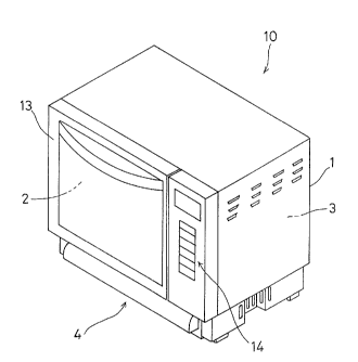
Figs. 1 to 3 show a microwave oven with a heating function
provided by a heater (hereafter referred to as an oven-range) in
accordance with an embodiment of the heat cooker in the present
invention. Theoven-rangelOismainlyconstructedwithanapparatus
body 1 constituting a cooker-body, a heating room 2 disposed in the
appa:ratus body 1, a high fre~uency supply section 3 disposed in the
apparatus body 1 and an accessory storage section 4 disposed under
the apparatus body 1.
The apparatus body 1 is mainly box-like and made of galvanized
CA 02233912 1998-04-02
steel plates. A base of the apparatus body 1 is made of a bottom
board 12 ~for example, see Fig. 4) having ventholes mentionedbelow.
A front of the apparatus body 1 is provided with a door 13 and an
operation panel 14 having a control section which is not shown in
Fig. 1. The high frequency supply section 3 is disposed behind the
operationpanell4intheapparatusbodyl. Thehighfrequencysupply
section 3 comprises a magnetron 31, a waveguide 32 and ahigh-voltage
transformer 33 as shown in Figs. 4 and 5. One end of a waveguide
7 is connected to the magnetron 31 and the other end thereof is open
to the heating room 2. A cooling fan 34 is disposed behind the
magnetron 31 and the high-voltage transformer 33 for supplying a
high voltage to the magnetron 31 is disposed below the fan 34.
The heating room 2 is box-like and made of steel plate with
an open front. A ceiling board 21 and a bottom board 22 each are
provided with a tubular heater 24 and a heater cover 23 constituting
a reflection board, the tubular heater 24 and the heater cover 23
facing the heating room 2. Further, a turntable 26 as a plate for
placing a stuff to be heated is rotatably held on the bottom board
22, lhe turntable being supported by a geared motor 25 constituting
a rotary motor disposed uncler the bottom board 22.
Referring to Fig. 6, thebottom board 12 is a rectangularsteel
plate formed along the bottom board of the apparatus body 1.
Generally on the left of the center of the bottom board 12, a
motor-storing recess 15 protruding downward via a step section 15b
is formed in order to prevent contact of the bottom board to the
geared motor 25 in Figs. 4 and 5. A plurality of ventholes 12a and
15a ~re formed on the front~ back and around the right side of the
recess 15 and the bottom part of the recess 15.
The step section 15b has no ventholes. If ventholes are
CA 02233912 1998-04-02
provided on the step section 15b, there is a fear that, when the
plate-like body 46 is pulled out from the accessory storage section
4and ametallicstickisinsertedintoanopenspaceformedbypulling
the plate-like body 46 in Figs. 4 to 7, the geared motor 25 located
above the bottom board 12 may be poked and damaged by the metallic
stick penetrating through the venthole on the step section 15b.
Therefore, no ventholes are disposed there.
Under the bottom boarcl12, a spacer 5 is disposed which forms
a space for ventilation men ioned below between accessories to be
stored in the plate-like body 46 and the bottom board 12.
The spacer 5 is a frame body made of steel plate, comprising
a mounting base section 51 and a spacer body section 53 extending
rearward from the mounting base section 51 via a downward slope
section 52. Two rectangular openings 5a are formed in the combined
area of the downward slope ,ection 52 and the spacer body section
53. Under three longitudin~l sides of rectangle sections 54
extending in a rearward direction to form the rectangular openings
5a, vertical pressing pieces 55 are disposed extending in the
rearward direction along the longitudinal side of the rectangle 54
and ~7ertically protruding d~wnward. The spacer 5 is, as shown in
Figs. 4 and 5, mounted onto a lower surface of the bottom board 12
bymeansofthemountingbase51, sothattheverticalpressingpieces
55 protrude from the bottom board 12 to the inside of the plate-like
body46. Theaccessorystoragesection4isdisposedunderthespacer
5.
The accessory storage section 4 is mounted to the bottomboard
12 on both right and left sides thereof (in Fig. 4) and comprises
a pair of leg bodies 41 supporting the apparatus body 1, a back cover
42 disposed between the two leg bodies 41 and a plate-like accessory
CA 02233912 1998-04-02
storage body 46 which is supported by the leg bodies 41 and inserted
in a space between the leg bodies 41 so as to be capable of being
pulled out as shown Fig. 7. The leg bodies 41, the back cover 42
and -the plate-like body 46 are molded members made from a
polypropylene resin. The resin forming the accessory storage
section 4 may be a synthetic resin material having a heat resistance
totemperatureof60~Corhigher,butisnotlimitedtoapolypropylene
reslrL .
The leg bodies 41 are formed like a parallelepiped container
having a rectangular cross section and disposed symmetrically with
each other. Outer side boa:rds 43 extend rearward along the right
and :Left sides of the bottom board 12. Inner boards 44 extend to
faceeachotherwiththesurfacesoftheinnerboards44beingparallel
At a center part of the outer side board 43 and the inner board 43
as v ewed in the direction I-rom the front to the back, a plurality
of ventilation slits 43a and 44a are provided in order to form an
airway between the inside of the apparatus body 1 and the outside
through the ventholes 12a and 15a on the bottom board 12 and the
area above the plate-like body 45, respectively.
At the center part of the outer side boards 43 as viewed in
the direction of the front to the back, handhold recesses 43b are
disposed in order to form h,~ndhold surfaces 12b (Fig. 4) having a
sufficient width for lifting up the oven-range 10 on the right and
left ends of the bottom board 12. The handhold recesses 43b are
inwardly caved.
Especially, as shown n Fig. 8, when the handhold recess 43b
at the side where the high frequency supply section 3 constituting
a control component is disposed (Fig. 4), i.e., at the side where
the operation panel 14 is disposed, is constructed to be wider than
CA 02233912 1998-04-02
the other handhold recess 4-3b provided at the opposite side, it is
easier to lift the oven-range 10 up. This is because the side where
thehighfrequencysupplysection3isdisposed, i.e., thesidehaving
the components like the high-voltage transformer 33 (Fig.4) is
heavier than the other side, so that a wider handhold section helps
a user to lift it up.
At the center of the inner boards 44 as viewed in a vertical
direction, rearwardly extending guide rails 45 are disposed facing
each other and are integral with the leg body 41. Each of the guide
rails 45 is capable of holding the edge of the opening of the
plate-like accessorystoragebody46mentionedbelow, has a constant
width, protrudes into the inside andisprovidedwith a guidingslope
45a at a front end thereof for guiding the plate-like body 46 in
and out.
The back cover 42 has a "U"- shaped cross section and is a
stick-like member extending in the direction from the right to the
left, partially having ventholes. The right and left ends of the
back cover 42 are engaged with and fixed to the back part of the
inner board 44 and the back cover 42 works as a cover for protection
of the accessory storage section 4 against dust.
The plate-like accessory storage body 46 is formed like a
para lelepiped container having a rectangular cross section,
comprising a front board 47 having a handle 47a for pulling the
plate-like body forward and a storage body section 48 for storing
accessories. An edge of the opening of the storage body section 48
has a constant width except the front part thereof and forms a
horizontally protruding flange 48a for sliding movement, the lower
side of the flange 48a being slidably supported by the upper side
ofeachguiderail45. Apairofguiderails45arecapableofholding
11
CA 02233912 1998-04-02
theplate-likebody46insertedbetween the right andleft legbodies
41, keeping the plate-like body 46 parallel to the bottom board.
The storage body section 48 is provided with a step section 48b in
order to center the accessories to be stored in the plate-like body
46, especially an oven plate mentioned below, in the storage body
section 48 away from either side of the storage body section 48,
the step section being disposed at three intersecting lines formed
by the inside bottom surface 49 and the right, left and rear side
surfaces. Additionally, thestepsection48bis formedtolackabout
a third of the front part in the direction from the front to the
back" whereby an accessory picking space 6 (Fig. 4) can be formed
for picking up the oven plate stored in the storage body section
48.
When the plate-like body 46 is inserted between the right and
left leg bodies 41, an upper end 47b of the front board 47 can retreat
to the position of nearly touching a front end of the bottom board
12 (Fig. 5), so that the upper end 47b is retained behind the edge
2a o:. the front surface of the heating room 2. Therefore, it can
prevent dropping of broken pieces of food materials to be heated from
the edge 2a of the heating room into the storage body section 48.
Fig. 9 shows concrete examples of storable accessories in the
accessory storage section 4. Examples of accessories S are a heat
insu:Lation mitten 101, a recipe book 102, a gridiron 103, a square
oven plate 104 and a handle for taking the oven plate out (not shown).
A lower surface of the bottom of the oven plate 104 is held by the
upper surface of the bottom 49Of the storage bodysection 48, whereby
a lo~Jer surface of an outwardly and almost horizontally protruding
edge 104a and an upper surface of the step section 48b of the storage
body section 48 are spaced apart.
12
CA 02233912 1998-04-02
As forventilationintheoven-rangelO, especiallyventilation
around the accessory storage section 4, an air flow is shown by an
arrow illustrated in Figs. 4 and 5. A broken arrow represents an
air flow in the case of high--frequency heating by operating the high
frequency supply section 3 A solid arrow represents an air flow
in the case of oven heating by operating the heater 24. When the
plate-like body 46 is inserted between the left and right leg bodies
41 and the above-mentioned accessories S are stored in theplate-like
body 46, the heat insulation mitten 101 or the like are pressed down
by the vertical pressing pieces 55 placed above the accessories S
even if the accessories S are bulky, and a space for ventilation is
secured between the accessories S and the bottom board 12.
In the case of high-frequency heating, an air flow generated
by the cooling fan 34 cools the magnetron 31, the high-voltage
transformer 33 and inner apparatuses such as the geared motor 25,
and a part of the air flow is discharged from the side board of the
apparatus bodyl to the outside. Further, some ofthe air flowpasses
over the plate-like body 46 through the ventholes 12a and 15a of the
bottom board 12 and is discharged through the ventilation slits 44a
and 43a to the outside. Since the above-mentioned space for
ventilation is secured by the vertical pressing pieces 55 between
the lower surface of the recess 15 of the bottom board 12 and the
accessoriesSstoredinthep]ate-likebody46, sufficientventilation
is provided also through the ventholes 15a of the recess 15, so that
cooling of the inner apparatuses is not prevented by the accessory
storage section 4.
In the case ofoven heating, a natural air convection generated
inside of the apparatus body 1 by heating of the heater 24 forms a
cooling air flow which flows towards the apparatus body 1 from the
13
CA 02233912 1998-04-02
outside. A fresh air flows inside from the ventilation slits 43a,
passes through the inside ventilation slits 44a and over the
plate-like body 46, and then a part of the above-mentioned fresh air
flows into the apparatus body 1. Moreover, a part of the above-
mentioned fresh air passes through the room for ventilation ensured
by the vertical pressing pieces 55 between the lower surface of the
recess 15 of the bottom board 12 and the accessories S, and flows
into the apparatus body 1 through the ventholes 15a. This air flow
cools the inner apparatuses such as the geared motor 25 and prevents
a damage thereof. Moreover, the vertical pressing pieces 55 keep
the accessories S away from the comparatively hot bottom board 12,
so t]-Lat a safe storage of the accessories S can be maintained.
In the above embodiment, the spacer 5 is constructed with the
vertical pressing pieces 55 which protrude to the inside of the
plate-like body 46 inserted between the leg bodies 41, the spacer
5 being disposed under the bottom board 12. However, as shown in
Figs. 10 and 11, a pairofelongatedprojections 59 formed toprotrude
downward by embossing the bottom board 12 can act as a spacer that
form., a space for ventilation between the accessories S to be stored
in the plate-like body 46 and the bottom board 12 as mentioned above.
Because the elongated projections 59 may be formed by embossing
simultaneously with making holes for the ventholes 12a at the time
offormingthebottomboard12, theproductionprocessbecomeseasier.
Moreover, since round edges can be formed, the accessories S are not
caught by the elongated projections 59.
Another embodiment of the spacer 5 is shown in Figs. 12 and
13. Here, at four corners of the lower surface of the bottom board
12, ahemisphere 69madeofasyntheticpolymeris disposedtoprotrude
downward and can act as a spacer that forms a space for ventilation
14
CA 02233912 1998-04-02
between the accessories S to be stored in the plate-like body 46 and
bottomboardl2 asinthe abo~e-mentionedembodiment. Thehemisphere
69 may be fixed to the bottom board 12 by allowing at least one
engagement projection (not shown) protruding upward from the upper
flat surface of the hemisphere 69 to engage with the engagement hole
(notshown) ofthebottomboard12. Alsointhiscase, theaccessories
S can be prevented from being caught by the hemispheres 69.
Because the legbodies41 are formed in a container-like shape,
they have enough strength and contacting area so as to support the
oven-range 10 stably.
Because the leg bodies 41 each are provided with a guide rail
45 w]-Lich is formed integral with the leg body and extends in the
direction from the front to the back, the plate-like body 46 may
be pulled out directly forward with small power. Moreover, it is
not necessary to attach an additional separate component as a guide
rail. Moreover, because the leg bodies 41 are provided with the
hand]~Lold recesses 43b, the handhold surfaces 12b for lifting up the
oven--range 10 are formed at the right and left outer ends of the
bottom board 12 and therefore, it is easler to lift up and transfer
the oven-range 10.
Theplate-likebody46isprovidedwithstep sections48bwhich
are :Eormed to lack a portion of the front part, whereby the space
for ]ighting up the oven plate stored in the plate-like body 46 can
be formed, so that the oven plate 104 can be kept apart from the
side surface of the plate-like body 46 and thereby, the oven plate
104 and the accessories stored therein can be easily taken out from
the plate-like body 46. Moreover, because the plate-like body 46
is constructed to be capable of being inserted to a position behind
theedge2aoftheheatingroom2, itcanpreventdroppingofmaterials
CA 02233912 1998-04-02
to be cooked from the heating room 2 into the plate-like body 46
andt:hereby, the lnside of the plate-like body 46 can be kept clean.
Figs 14 to 17 are views for explaining a spacer 500 as another
embodiment of the spacer 5 in Fig. 6.
The spacer 500 comprises a rectangular base board 501 having
a pll1rality of ventholes 502, a side board 503 disposed on the
longitudinal side of the base board 501 to secure a space for
ventilation between the base board 501 and the bottom board 12 and
a fixing piece 504 extending from a portion of the side board 503
contactingthebottomboardl2 forfixingthespacer500tothebottom
board 12 by fastening screws. That is, the spacer 500 is formedlike
a di-ch having a "U"-shaped cross section.
The spacer 500 is fixed under the motor-storing recess 15 of
the bottom board 12 in order to ensure the ventilation through
ventholes 15a provided on the motor-storing recess 15. The spacer
500protrudes fromthemotor-storingrecess15becausethebaseboard
501 is a rectangle. At the protruding part, a broad section 503a
conslituting a partially wider side board 503 is disposed so as to
be attached onto the motor-storing recess 15 and the base board 12
having ventholes 12a, as shown in Fig. 15.
Moreover, this spacer 500 is positioned in such a manner that
the two openings formed by the "U"-shaped cross section face to the
righ1 and left directions as viewed from the front of the oven range
10. That is, the side board 503 of the spacer 500 is disposed so
that the side board 503 stands parallel to the front board 47 of
the plate-like body 46.
The reason why the spacer 500 is disposed in such a direction
isasfollows. Thatis, ifthespacer500isdisposedinthedirection
from the front to the back, mittens or the like to be stored will
16
CA 022339l2 l998-04-02
touch an opening part formed by the "U" shape, raising a fear that
theycannotbestoredwellbecausetheywillbecaughtbythisopening
part. If the spacer 500 is disposed in the direction from the right
to the left as in the present invention, mittens or the like can
be stored smoothly even if they touch the side board 503, because
the side board 503 forms a wall as shown in Fig. 15.
Moreover, themotor-storingrecess15isdisposedtobeshifted
to the left side of the bottom board 12, as viewed from the front,
for placing the high frequency supply section 3 behind the operation
panel 14 at the right side of the apparatus body 1. Accordingly,
inthisembodiment,thespacer500ismountedsothatthebroadsection
503a is disposed at the left side of the motor-storing recess 15.
As a result, the spacer 500 is placed near the ventilation slits
44aofthe legbodies 41, thus enabling a more efficient ventilation.
Figs. 18 to 20 show another embodiment of the plate-like body
46 in the accessory storage section 4. Here, a sliding step section
78bisformedatthreeintersectinglinesformedbythebottomsurface
49 and the right, left and rear side surface of the storage body
section. The sliding step section 78b protrudes horizontally with
a constant width and is formed to lack about a third of the front
part in the direction from the front to the back. The sliding step
section 78b supports accessories to be stored in the plate-like body
46, especially the oven plate mentioned below, keeping them spaced
away from the bottom 49 of the storage body section 48. That is,
the oven plate 104 is retained in the state of being spaced away
from the bottom 49 of the storage body section 48 as shown in Figs.
18 and 19, thereby preventing the ventholes 49a from being blocked
by the bottom of the oven plate 104 and securing a space for
ventilation.
17
CA 02233912 1998-04-02
When an oven heating is conducted, a natural convection
generatedintheapparatusbodylbyheatingoftheheater24generates,
in this space, a cooling air flow that flows to the inside of the
appa:ratus body 1 from the outside. A fresh air flows in through the
ventilation slits 43a and 44a and passes over the plate-like body
46, with a part of the air flowing into the apparatus body 1 through
the ventholes 12a of the bottom board 12. A part of the fresh air
flow passes through a space secured between the bottom surface of
the recess 15 of the bottom board 12 and the accessories S by the
vert:ical pressing pieces 55 and flows into the apparatus body 1
through the ventholes 15a. Moreover, a fresh air can also be taken
in through the ventholes 49a formed on the bottom surface 49 of the
stor~ge body section 48. By such an air flow, the geared motor 25
and lhe like are cooled and therefore, a damage of the inside
apparatuses can be prevented. Accordingly, because the plate-like
body 46 is provided with the step section 78b, the oven plate 104
can be kept spaced apart from the bottom of the plate-like body 46
and t:he accessories S can be easily taken out from the plate-like
body 46.
As is apparent from the embodiments of the present invention,
the heat cooker of the present invention does not prevent discharge
of heat from the inner apparatuses even if the accessory storage
sectionincludingastructureforinsertingtheplate-likeaccessory
storage body between the leg bodies is disposed under the bottom
boarcl of the cooker body, because the leg bodies constituting the
accessory storage section are provided with ventilation slits that
form an airway between the inside of the cooker body and the outside
through the ventholes of the bottom board of the cooker body and
an area above the plate-like body.
18