Note: Descriptions are shown in the official language in which they were submitted.
CA 02233960 1998-04-03
W O 97/12S4Q - PCT~US96/15989
IMPROVE~) APPAR~TUS FOR APP~Y~NG X-RAYS TO AN
INTERIOR SURFACE OF A BODY CAVlTY
,.
REF~RENCE TO RELATED APPLICATION
This application claims the benefit of U.S. Patent Application Serial
No. 60/004,921, entitled Improved Ap~a~dlus for Applying X-rays to an
Interior Surface of a Body Cavity, filed October 6~ 1995
BACKGROUND OF DISCLOSURE
The present invention relates ~o a mini~nlrizedr low power,
pro~,ldmlllable x-ray source for use in delivering specifically contoured
doses of x-rays to a specified region. More specifically, the invention
relates to appalal~ls and mefh~ s for delivering desired x-ray flux to interior
surfaces of body cavities.
X-radiation applied to the soft tissue lining body cavities is known to
be useful in the treatment of certain cancers, including cancer of the
bladder, vagina and cervix, urethra, uterus, colon and rectum. In an ideal
Ll~ P.-t for many conditions, only the surface of the body cavity, i.e., the
target tissue, is exposed to the radiation. However, most conventional,
radiation therapy utilizes an external radiation source which directs relativelyhigh energy, and thus tissue--l~m~ging, x-rays toward the patient, so that the
x-rays must first penetrate the skin and other tissue of the patient, prior to
re~ching the tissue lining the body cavity. Undesirable radiation of non-
target tissue is thus an unavoidable consequence of having a conventional x-
ray source located outside the patient's body. Further, the use of relatively
high energy, and thus tissue ~l~m~ing, x-rays are required to insure that a
sllfflrient dose is delivered to the target tissue.
Convemion~l methods of radiation treatment for tissue lining body
cavities also fail to provide the ability to deliver a specific dose of radiation
CA 02233960 1998-04-03
W O 97112540 PCT~US96/15989
to the target tissue, whicn may have an arbitrary contour. In some cases, it
is desirable to providë a subst~7nti~lly ul~iru~ dose of radiation over a
relatively large target area. In other cases, specifically contoured non-
uniforrn doses may be desired. As used herein, the tern "isodose collLuui"
5 refers tO a surface over which the x-ray flux density is substantially
constant. In tne context of an interior surface, or lining of a body cavity, a
uniform dose implies generating an x-ray distribution having an isodose
contour that is coincident with the interior surface of the cavity.
Some of these disadvantages of the prior art approaches can be
10 overcome through the use of a mi~ ed low power x-ray source, such as
the one described in the above-referenced U.S. Patent No. 5,153,900
granted to Nomikos et al. That x-ray source includes an elongated tube
ext~?n~lin~ along a source axis, and has an electron beam ge~ or at one
end which generates and directs an election beam along the source axis to
15 the other end and in here it is inric~en~ upon a target which is reprone to tne
beam to gellel~Le x-radiation.
That source can be inserted into a patient's body, and imm~ tely
ent to a tissue to be treated, and then activated to genelaLt; x-rays from
within, perrnitting g~ne~dlion of x-rays from points local to the target
20 tissue. When such an x-ray source is used to treat the tissue lining a body
cavity, the x-rays need not pass through the patient's bone mass, and skin,
and other tissue prior to reaching the target tissue.
One useful a~a-aLus for delivering radiation to the interior surface
of a body cavity uses a combination of a mini~hlrized low power x-ray
25 source of the type disclosed in U.S. Patent No. 5,530,900, and an inflatable
balloon. The above-referenced U.S. Patent Application Serial No.
0~/273,645, entitled X-ray Apparatus for Applying a Predetermined Plux to
an Interior Surface of a Body Cavity, describes one such combination. This
a~ aLus uses a g~ nre (or balloon) tube with a balloon affixed to its
30 distal tip, where the balloon stretches the body cavity to a desired known
shape, such as a sphere. The x-ray source is advanced through the balloon-
CA 02233960 1998-04-03
W O 97/12540 - PCT,~US96/15989
tube so that its x-ray generating distal tip is positioned at a pred~ p{~f
location, for example, the center, within the infl~t~d balloon, and then is
activated. In cases where it is desired to apply a uniforrn dose to the lining
of a body cavity having a flexib}e defining boundary (such as the bladder), a
5 substantially spherical (when inflated) balloon is positioned in the cavity and
in~ttod, thereby forcing a spherical shape to the def,ining boundary, and
thus the lining. Then a subst~nti~lly omni-directional x-ray source is
positioned at the center of the inflated balloon. With such a configuration,
x-rays gen~l.tLed from within the inflated balloon establish a ~b~ ly
10 ullirOllll dose at the surface of the body cavity.
One important aspect of that approach is the ability to locate the x-
ray source at a predetermined location within the body cavity. Tnfl~ting the
balloon can stretch the body cavity to a known shape, but internal pressures
near the cavity can cause the balloon-cavity structure to shift in position
15 relative to the balloon tubes, thereby causing a mi~lignment between the
balloon axis and the axis of the x-ray source. If the x-ray source can not be
positioned accurately, it then becomes ~iiffi~ to deliver a unifolln dose to
the surface of the body cavity.
Another combination of an x-ray probe and a balloon is described in
20 U.S. Patent Application Serial No. 08/273t963, entitled Improved ~-ray
Apparatus for Applying a Predeterrnined Flux to an Interior Surface of a
Body Cavity. In this combination, opposite ends of a balloon are
p~ ly aff~ed to and disposed about an extension of a balloon-tube,
which passes along a ~ m~t~r of the balloon when infl~te(l In operation
25 with this configuration, the balloon-tube and ~efl~d balloon are inserted
into the body such that the deflated balloon is initially positioned within the
cavity and the balloon is then inflated. The balloon-tube and its extension
m~int~in ~lignm-ont between the balloon-tube and the balloon. The x-ray
probe is then inserted into the balloon-tube and positioned with its x-ray
30 gel~ldL,i1~ distal tip at a predetermined location along a ~i~m~t~r of the
CA 02233960 1998-04-03
W O 97/12540 PCT~US96/1~989
balloon so that x-rays can be g~ d from a known location within the
. .
body cavity.
One problem the with latter configuration is that the deflated balloon,
when packed around the balloon-tube, forms a structure that is relatively
5 large in diameter making insertion into and retraction from body
passageways difficult. This is an important factor for relatively small
passageways, such as the urethra, into which the structure is inserted for x-
ray treatment of the bladder. Further, in such configurations, the balloon-
tube is typically only partially tr~ ,ni.c~ e of x-rays and hl~ ,s with the
10 ability to deliver a ~ecificdlly collL(lul~d dose to the target tissue.
Also, with the above described configurations, the M~ tin~ tip of the
probe can not be placed close to a cavity wall in a manner perrnittin~
radiation of local lesion on that wall.
It is therefore an object of the invention to provide an improved
15 method and apparatus for delivering a specifically col.L~ ed dose of
radiation to the tissue lining body cavities.
It is a further object of the invention to provide an ~al~lus, that
inr~ es a ~ low power x-ray source and a balloon, for delivering
unirollll or other desired doses of radiation to the tissue that lines a body
20 cavity.
Other objects and advantages of the present invention will become
a~L~alell~ upon consideration of the appended drawings and description
thereof.
25 SUMMARY OF THE INVENTION
The fol~goillg and other objects are achieved by the hl\~nlion which
in one aspect comprises a balloon assembly for stretching a body cavity to a
predeterrnined shape. The assembly includes a g~ n~e ç~nn~ , a balloon-
tube and a balloon. The c~nm-l~ is relatively rigid and has proximal and
30 distal ends and extends along a c~nm-l~ axis. The balloon-tube has ~lv~hllal
and distal ends and defines an interior channel exton~ling along a central
,
CA 02233960 1998-04-03
W O 97/12540 - PCT~US96/1~989
axis. The balloon-tube has an outer contour adapted to slidingly fit within
the c~nm-l~ so that the c~nn~ and central axes are s~hst~nti~lly coaxial.
An inflatable subst~nti~lly inelastic balloon is affixed tO the distal end of the
balloon-tube. The interior channel of the balloon-tube is contiguous with
S and connPctf~rl to the interior of the balloon so that inflation and deflation of
the balloon may be controlled from the proximal end of the balloon-tube.
When infl~t~l, the balloon de~mes a predeterrnined surface contour disposed
about an interior region extending along a balloon ~tt~f~hment axis, or
balloon axis, which extends across a ~ m~ter of the balloon from the
10 junction of the balloon-tube and the balloon. The balloon axis inLcl~e~ the
central axis of the balloon-tube near the distal end of the balloon-tube.
In operation, the c~nnnl~ may be inserted through a body
passageway, e.g., the urethra, so that the distal end of the c~nn~ is
positioned near a body cavity, e.g.~ the bladder, and so that the proxirnal
15 end of the c~nn~ c.,laills external to the body. The balloon~tube and
balloon, when deflated, may then be il~.Lcd through the c~nmll~ so that the
balloon is positioned beyond the distal end o~ the ç~nmll~ and within a body
cavity. The balloon may then be inflated and thereby stretch the body
cavity to a pre~l~t~rmin~d shape. When the balloon-tube is inserted into the
20 c~nmll~, the central and canula axes are nnrrn~lly coaxial.
Although the balloon axis and the central axis of the balloon-tube
intersect, they are generally not axially aligned imrnediately following
inflation of the balloon. While the balloon is sllbst~nti:llly in~ ti~, the
m~teri~l forming the balloon at the ~tt~chment between the balloon and the
25 balloon-tube somewhat ~lexible, permitting the oliell~tion b~Lwe~n the
balloon axis and the balloon-tube to be easily ch~n~ The angle between
the central and balloon axes may be adjusted by rotating the c~nm~l~ about
the point of i~lhl~ection of the balloon and central axes, thereby permitting
ctrnPnt of the central and ~nmll~ axes into a desired angular ~lignmPnt
30 The assembly of an aspect of the invention further includes an ~lignm~nt
mf ch~ni~m that is operative from the proximal end of the c~nmll~ for
CA 02233960 l998-04-03
W O 97/12540 PCT~US96/lS989
selectively adjusting the angle between the balloon and c~nmll~ axes to a
prec~etermin~l angular orientation. Preferably, the angle between the
balloon and c~nn--l~ axes is adjustable between zero and 90 degrees.
The ~ nm~nt mechanism may include a .~re,~;nce mark, or region,
S which is rletPct~ble (e.g., optically (letect~hle) from the interior of the
balloon. The reference mark may be located at f~e intersection o~ the
balloon and the balloon axis opposite the intersection of the balloon and
central axes, and the reference mark may be located on the exterior of the
balloon in the case of a transparent or tran~ll-rPnt balloon, or on the interior10 of the balloon. The position of the reference mark relative to the c~nn~
axis is determinable from within the interior region of the balloon, so that a
user can observe the position of the mark relative to the c~nmll~ axis? and
thus know the angular orientation of the balloon axis relative to the c~nn
axis.
In one form the reference mark may fluoresce in response to incident
light in a predele~ ed spectral range. For that form, light in that spectral
range may be directed via a filter to the balloon interior. An operator may
m~nipul~te the c~nn--l~ axis relative to the balloon axis of the infl~t~d
balloon while mo~ h.g the balloon interior via an output filter at a wave-
20 length associated with the fluo,cscellce, to detect fluo.~scellL light from the
reference mark and determine when the cannula axis is aligned with the
balloon axis.
The assembly may also include an inflation assembly disposed near
the proximal end of the balloon-tube for controlling the pressure in the
2~ interior region of the balloon. The inflation assembly may provide a gas
flow path exf~n~ing between a pressure source and the interior channel.
In another aspect, the invention provides a kit for applying x-rays to
an interior surface of a body cavity. The kit includes an x-ray source that is
cooperative with the above-described assemblies. The x-ray source in-
30 cludes an x-ray gel~dtol disposed at or near a target end of an elongated
tubular element.
CA 02233960 1998-04-03
W O 97/12540 - - PCTAUS96/15989
The x-ray generator may be an ornnidirectional generator. The target
end may also include a shield for controlling the spatial distribution of
isodose contours of the x-rays emitted by the x-ray generator. The shield
may be characterized by a selected x-ray trrn~mi~ion spatial profile.
The balloon when inflated may be spherical. However, the use of
ba}loons having cylindrical, or other shape that may be desired for a
particular cavity-to-be-illllmin ~ Symmetry, or no syrnmetry at all is also
used for various forms of the invention. In such cases, to deliver a pre-
scribed dose of radiation to the body cavity walls, the x-ray source may be
mrQ~ , as is described for example in tne above-.Gf~ ced U.S. Patent
Application Serial No. 08/184,271, entitled X-ray Source With Shaped
Radiation Pattern, and/or tr~.ncl~f~i along the c~nmll~ axis during the
exposure to radiation as described in U.S. Patent 5,153,900.
BRIEF DESCRIPTION OF DRAWINGS
The foregoing and other objects of this invention, the various fea-
tures thereof, as well as the invention itself, may be more fully understood
from the following description, when read together with the accompanying
drawings in which:
Figure 1 is a cross sectional view of an ~IJald~Us according to the
invention useful for providing radiation treatment to the interior surface of a
body cavity, including a balloon-tube and an inflated balloon;
Figure 2 is a view of tne a~~~aldLlls shown in Figure 1 in which the
balloon is deflated;
Figure 3 is a perspective view of a mini~hlre x-ray probe according
tO the invention;
CA 02233960 1998-04-03
WO 97/12540 PCT/US96/l5989
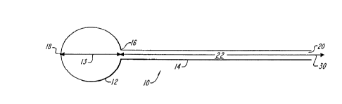
Preferably, balloon l2 contains a ~t;felcllce, or fiducial, region or
mark 18 at the distal ënd of balloon axis 13. The mark 18 is observable
from the interior of the inflated balloon for facilit~ting ~ nmPnt of balloon-
tube axis 30 and the inflated balloon axis 13, as will be ~ cl-cse~1 further
5 below. Thus, l~ft;l~nce mark 18 is preferably located where axis 13
intersects the surface of balloon 12 as shown in Figure 1. In alternative
embodiments, lc~f~.~nce region 18 may include a plurality of marks disposed
in a circularly symmetric pattern centered on the distal end of axis 13 and
balloon 12. The mark 18 may be located either inside or outside balloon
10 12.
In use, balloon 12 contacts the tissue 1ining a body cavity and
therefore is preferably composed of a biocompatable material. In the illus-
trated emboclimt~nt, balloon 12 is an inelastic balloon, m~:lning that inflationwill expand balloon 12 to a predeLe~ P~i shape and further inflation will
not further alter the balloon's shape but will only increase interior ~ ule,
and accordingly, the rigidity of the balloon. Balloon 12 is also preferably
lld~ arenL, so body surfaces and any .o~rt~rn~l reference mark can be
viewed from the interior of the infl~tPd balloon.
The balloon-tube 14 is sized to permit insertion into a ~nmll~ which
in turn is sized to facilitate insertion into body passageways such as the
urethra, and the balloon is preferably chosen so that when deflated, as
shown in Figure 2, the balloon 12 can be packed into a region having a
m~ter no larger than that of the inner ~ m~ter of the c~nmll~ or more
preferably no larger than the outer ~ mloter of the balloon-tube 14.
The a~dldLIls of the present invention may also include an electron-
beam (e-beam) activated x-ray source. That source may operate at relative
low energy as in the range of approximately 10 kV to 90 kV, and relatively
small electron beam ~;u~,~.,~, as in the range of approximately 1 nA to 1
mA. Such a source is described more completely in the above-ltferellced
U.S. Patent No. 5,153,900 granted to Nomikos et al.
lQ
CA 02233960 1998-04-03
W O 97/12~4Q - - PCT~US96/15989
Figure 3 shows sucp an x-ray source 110 which includes an elon-
gated cylindrical probe 114 e~t~n~in~ along a lcrt~ ce axis 116 from a
housing 112 and having a target assembly 126 at its distal end. The housing
112 encloses a power supply 112A. The probe 114 is a hollow tube having
at its proximal end an electron beam gelle.dLOl (cathode) 122 and an associ-
ated high voltage power supply 112A. Cathode 122 is located in close
proximity to an annular focusing electrode 123 typically at nearly the same
potential as the catnode 122. The hollow, tubular probe 114, the cathode,
grid, and tne hole in the anode all extend along an axis 116. An associated
controller controls the greater of these elements to generate an e-beam, and
direct that beam along axis 116 to the target assembly 126. The target
assembly, in response to this incident e-beam, generates x-rays. In various
embodiments, parts of the probe 114 are preferably selectively .shiPI~Pd to
control the spatial distribution of x-rays. In addition, the probe 114 is
preferably m~n~ti~lly ~hieldpf~ to prevent external m~gn~-tir fields from
deflecting the beam away from the target.
Figure 4 shows a kit 210 according to the invention for delivering x-
rays to the tissue lining a body cavity. Kit 210 includes balloon 12,
balloon-tube 14, and x-ray probe 114 (housing 112 is not shown). Kit 210
2û further inc~ s an elongated tubular carmula 214. ~nmll~ 214 defines an
axis 230 and has an inner diameter slightly larger than tne outer di~m~tPr Of
balloon-tube 14, such that balloon-tube 14 and balloon 12 when deflated are
slidably positionable within an interior channel 222 of cannnl~ 214 so that
balloon-tube axis 30 is substantially coaxial with c~nnnl~ axis 230. Prefera-
bly, the walls of c~nmll~ 214 includes interior channels which permit flow
therethrough of a fluid coolant. Preferably, the walls of c~nn~ 214 also
include channels permit~ing flow of urine from the bladder, as well as the
flow of gas into the bladder (so that the bladder can be inflated to facilitate
inflation of the balloon 12).
A proximal end 220 of c~nm-l~ 214 is integrally mounted to a
cooled-c~nn-ll~ water and urine manifold 223 which is supported by a
11
CA 02233960 1998-04-03
W O 97112540 PCTAUS96/15989
r~ocking clamp (or block) 224 useful for ~lignin~ c~nn~ 214 as will be
c~-ssed further below. Manifold 223 also allo~s gas (preferably (CO2) to
be introduced through the urine channel in order to inflate the bladder.
Balloon inflation is accomplished by means of gas inlet 64 as described
5 be10w.
In a preferred embodiment the c~nmll~ 214 is constructed from
surgical steel or other biocompatable material. In use, the c~nn-~l~ 214 is
inserted into body passageways, such as the urethra, or surgically made
passageways. Since c~nnl~l~ 214 is relatively rigid, balloon-tube 14 may be
10 relatively flexible and may be fabricated from, for example, light weight,
thin, plastic.
Figure 4 shows proximal end 20 of balloon-tube 14 integrally
mounted in a pressure-lock module 50, which provides for the introduction
of gas pressure into the balloon and subsequent introduction of an endoscope
15 or the x-ray probe into the balloon without losing pre~u-e in the balloon.
Pressure-lock module 50 defines an interior channel 52 e~ctP~r~ing from
proximal end 20 of balloon-tube 14 to an end 60 of ~ u~e-lock module 50
such that interior channel 52 is conn~oct~rl to and coaxial with interior
channel 22 of balloon-tube 14 (shown in Figure 1). Interior channel 52 is
20 sized such that x-ray probe 114 is slidably positionable within channel 52.
The balloon-tube 14 is affixed to pressure-lock module 50 by way of
a clamp 233. Figure 4 shows balloon-tube 14 inserted within c~nmll~ 214
such that the distal end 16 of balloon-tube 14 extends beyond a distal end
216 of c~nmll~ 214. In this position, balloon 12 is free to expand without
25 being constricted by c~nmll~ 214. Figure 4 further shows x-ray probe 114
inserted within balloon-tube 14 such that x-ray target 126 is centered within
inflated spherical balloon 12.
Pressure-lock module 50 includes a sealing 0-ring 62 for forming an
air-tight seal with probe 114 for ~c~elllhlg p~ u~ ed gas from escaping
30 inflated balloon 12 when probe 114 is inserted within channel 52. 0-ring 62
is preferably made of rubber or other resilient material suitable for forming
CA 02233960 1998-04-03
W O 97/12540 PCT~US96tl~989
air-tight seals. In addltion to O-ring 62, pl~;s~ulc-lock module 50 may
include other o-rings distributed in a conventional ~ashion through module
50 to assist in forming a gas-tight seal with probe 114.
Plc:s~ul~-lock module 50 further provides a plts~ul~ port 64 which
S may be coupled to a tank of ~lcs~uliGed gas or a pump (not shown) for
controlling inflation and deflation of balloon 12. Pressure-lock module 50
further provides gate valve 66 and O-rings 68 for sealing channel 52 and
thereby m~int~ining pressure within balloon 12 when the x-ray probe or an
endoscope are not present in o-ring 62. Gate valve 66~ which is shown in
10 an open position in Figure 4, is slidably mounted within pressure-lock
module 50. In its open position, gate valve 66 does not obstruct channel 52
and allows probe 114 to be inserted into balloon-tube 14. When probe 114
is withdrawn, gate valve 66 can slide dowllwdlds such that O-rings 68 and
gate valve 66 form a gas-tight seal preventing gas from flowing between the
15 interior of balloon 12 and end 6() of ~lc;,~ e-lock module 50.
P~ ù~e lock module 50 thus provides several methods for control-
ling the inflation and deflation of balloon 12 while introducing either the
probe or endoscope into the balloon. For example, if balloon 12 is initially
deflated, gate valve 66 may be moved dow--wdl-ls to its closed position and
20 a gas pump (not shown) can pump gas through pressure port 64 into balloon
12 until the balloon is inflated to a desired pressure. Gate valve 66 and O-
rings 68 prevent any gas from escaping through end 60. Once probe 114,
or other such instrument, is inserted into channel 52 such that target end 126
is beyond O-ring 62, gate valve 66 can be retracted to its open position as
25 shown in Figure 4. The seal formed by O-ring 62 and probe 114 will
prevent any gas from escaping the balloon. Probe 114 can then be inserted
such that target 126 is positioned at a desired location within inflated balloon12 as shown in Figure 4. This final insertion of probe 114 increases the
ples:,ulc; inside balloon 12 slightly because probe 114 drives some of the gas
30 that was inside ch~nn~l 22 into balloon 12. This slight increase in pressure
is gen~rally nPgligihle and does not illL~ with the operation of kit 210.
CA 02233960 1998-04-03
W O 97/12540 - PCT~US96/15989
However in some situations, it is desirable to connect a pressure control
valve (not shown) to port 64 to m~int~;n constant pressure within balloon 12
as probe 114 is being inserted.
The operation of kit 210 will now be ~ c~ e~l in col~n~ ion with
providing an exemplary radiation treatment to a bladder. As those skilled in
the art will appreciate, radiation treatment of other body cavities can be
accomplished in a similar manner. Referring to Figures 5A and SB, initially
c~nmll~ 214 is inserted into tne urethra of a patient such that distal end 216
is positioned near the i,lLe.~eclion of a uretnra and a bladder 300. Proximal
end 220 of c~nmll~ 214 remains outside the body of the patient. The body
wall of tne patient is shown schem~3ti~lly at 302 in ~igure 5A. As is
further shown in Figure 5A, the bladder 300 initially has an irregular shape.
In the preferred embodiment, kit 210 includes a V-guide 410 used
for ~lignmpnt as will be ~ cl~ssecl further below. V-guide 410 provides a
surface bearing a V-shaped groove 412 exl.ontling along an axis 430.
Docking clamp 224 may be fixed to one end of V-guide 410, and manifold
223 may be clamped to docking clamp 224. When manifold 223 is cl~ml~ed
to ~lock~tng clamp 224, the c~nnlll~ axis 230 of c~nmll~ 214 is parallel to axis430 of V-guide 410.
Once c~nmll~ 214 is inserted into the patient so that the distal end
216 is positioned near the intersection of the urethra and the bladder, V-
guide 410 and c~nmll~ 214 are aligned by clamping manifold 223 to docking
clamp 224. Next, pressure-loclc module 50 is positioned on V-shaped
groove 412 as shown in Figure SA. When ~ s~.ul~-lock module 50 is
positioned on groove 412, the balloon-tube axis 30 of balloon-tube 14 is
sll'cst~nti~lly coaxial with c~nmll~ axis 230. Initially, balloon 12 is deflatedand is packed so that it extends along central axis 30 and so that the outer
mPt~r of balloon 12 does not exceed the outer diameter of balloon-tube
14. Pressure-lock module 50 is tnen advanced along groove 412 towards
docking clarnp 224 so that deflated balloon 12 and balloon-tube 14 are
inserted through c~nml~ 214. Preferably, the components are sized so that
14
....
CA 02233960 1998-04-03
W O 97/12540 PCT~US96/15989
when pressure-lock module.50 abuts docking clamp 224, the distal end 16 of
. .
balloon-tube 14 extends just beyond the distal end 216 of c~nn~ 214 so
that balloon 12 extends into the bladder 300.
Pigure 6 shows ~r~ c-lock module 50 abutting docking clamp 224
S and balloon 12 inflated so that balloon 12 has stretched b}adder 300 to a
uniform spherical shape. In many cases it is desirable to inflate bladder 30û
(via gas flow in the urine channels of cannula 214) prior to inflation of
balloon 12 so that minim~l stress is applied to the bladder during inflation of
the balloon. As is shown in Figure 6, after balloon 12 is infl~t~-d, internal
pl'cS~w'~S from the patient's body typically cause balloon 12 to shift relative
to c~nn--l~ 214 so that balloon axis 13 is angularly of~set with respect to
c~nn~ /balloon-tube axes 30, 230. This mi~lignm~nt occurs because, even
though balloon 12 is inelastic or non-stretchable, the junction between
balloon 12 and guidance tube 14 is flexible. As a consequence of such a
15 mi~lignm~nt of axes 13 and 30, it is ~iffi~lllt to insert an x-ray probe 114
through g-liA~n~e tube 14 so that its tip 126 is positioned at the center of
balloon 12.
Figure 7 shows an endoscope 500 inserted into the balloon 12. The
mi~lignment of axes 13 and 30 can be corrected by rotating V-guide 410
20 con~;ullcl~Lly with c~nn--l~ 214 and balloon-tube 14 about distal end 16 of the
balloon-tube ~which has been previously located near the neck of the blad-
der, i.e., the intersection of the urethra and the bladder, which is the most
anatomically desirable point of rotation for the tubes). The ~ nm~-lt of
axes 13 and 30 can be confinnf~A by use of an endoscope, or other optical
25 viewing instrument, for viewing fiducial mark 18.
As is well known in the art, endoscopes are normally constructed
from optical fibers or lenses held in ~ nm~nt by an e~ongated cylin~1ri~
casing. The outer Ai~m~-ter of endoscope 500 is preferably chosen to be
similar to that of X-ray probe 114 so that endoscope 500 forms a gas-tight
30 seal with IJ~cs~ulc-lock module 50. Insertion of endoscope 500 into balloon-
tube 1~ ll~Le~l~ does not cause loss of plCS:iUlC from balloon 12. ~ndo-
.
CA 02233960 1998-04-03
W O 97/12540 PCTAJS96/15989
scope 500 is shown fixed tQ a cylindrical endoscope holder 502 which is
sized so that when holder 502 rests on V-groove 412 the axis of endoscope
500 is coaxial with the axis 30 of balloon-tube 14 (shown in Figure 4) so
that endoscope 500 may be inserted into balloon-tube 14 simply by advanc-
S ing holder 502 along V-groove 412 towards pressure lock module 50. A
CCO camera 504 is attached to holder 502 to provide a display of the
interior of balloon 12 as viewed by endoscope 500. The optics of endo-
scope 500 preferably contain cross-hairs which are aligned with the central
axis of the endoscope 500. Alignm~nt of balloon axis 13 and balloon-tube
10 axis 30 may be achieved by aligning the cross-hairs of endoscope 500 with
fiducial mark 18.
Once ~lignm~nt of axes 13 and 30 has been achieved, V-guide 410 is
preferably locked into the proper position to preserve the ~lignm~nt Kit
210 preferably includes a multi-axis support system for supporting V-guide
15 410 (as shown in Figures 8A-B). Figures 8A and 8B show front and side
views, respectively, of a multi-axis support system 600. Preferably, support
system 600 provides at least five degrees of freedom (x, y, z, ~ (polar
angle) and ~ angle)) so that it can conveniently support V-guide
410 at any arbitrary angle while keeping the distal end of the balloon-tube
20 fixed in space. Figure 8A shows pr~ ul~-lock module 50 and endoscope
holder 502 resting on V-guide 410, and support system 600 SU~pOl~illg V-
guide 410. V-guide 410 is positioned so that axes 13 and 30 are not
~lign~-l Once ~ nm~ont has been achieved, the positions OI V-guide 410
and support system 600 are preferably fixed, or locked, so that a ~llr~eoll
25 may remove endoscope 500 and subseql~ntly insert x-ray probe 114 without
fear of disturbing the ~lignm~?nt.
Withdrawal of endoscope 500 and insertion of probe 114 are accom-
plished without loss of pressure from balloon 12 by use of gate valve 66
(since loss of pressure from, and reinflation of, balloon 12 may disturb the
30 ~lignn7~nt). Withdrawal of endoscope 500 is accomplished by retracting
holder 502 so that the distal tip of endoscope 500 is retracted Just beyond
16
. . .
~ : =
CA 02233960 1998-04-03
W O 97112540 ' PCT~US96/15989
gate valve 66 and such that it is still forward of O-ring 62 so that endoscope
500 still m~int~;n~ a gas-tight seal with pressure-lock module 50. Gate
valve 66 is then moved to its closed position (as shown in Figure ~) and
endoscope 500 is completely withdrawn from pressure-lock module 50.
Probe 114 is then inserted into pressure-lock module 50 so that target 126 is
forward of O-ring 68 so that probe 114 forms a gas-tight seal with pressure-
lock module 50. Gate valve 66 is then moved to its open position and probe
114 is inserted into balloon 12.
Figure 9 shows probe 114 inserted so that target 126 is centered
within infl~tt?(l balloon 12. Housing 112 of probe 114 is configured so that
when housing 112 rests on V-groove 412, probe 114 is aligned with axis 30
of balloon-tube 14 so that probe 114 may be inserted into balloon-tube 14
sirnply by advancing housing 112 along V-groove 412 towards pressure-lock
module 50. Further, housing 112 and probe 114 are preferably sized so that
when housing 112 abuts ~les~ -lock module 50, target 126 is centered
within infl~fed balloon 12.
Once target 126 is centered within balloon 12, x-ray source 110 is
operated to direct an e-beam to be inadent on target 126, which in turn
g~ W~t~:S x-rays. Since target 126 acfs as a nominal point source, it gener-
ates an x-ray field having spherical isodose contours. Therefore, a ulliro
dose of x-rays is delivered to the tissue lining the bladder 300.
After treatment, probe 114 is removed, and then balloon 12 is
~lefl~tP-1 as described above. Deflated balloon 12, gni~l~nre tube 14 and
c7~nmll~ 214 are then withdrawn from the body.
Accol.li,lgly, kit 210 allows delivery of a uniform dose of x-rays to
the tissue lining a body cavity. Since the x-rays are generated from witnin
the cavity, the x-rays need not first penetrate the patient's bone mass or
skin, and other tissue prior to reaching the target site. Thus, kit 210 allows
delivery of a uniru~ln dose of x-rays to the target tissue subst~nti~lly withoutr~ fing non-targeted tissue. Further, since the x-rays need not first
17
CA 02233960 1998-04-03
W O 97/12540 PCTAJS96/15989
pe"etl~te non-target tissue p}ior to reaching the target site, relatively low
energy x-rays can be used, compared to the prior art.
In addition ~o providing a uniform dose of radiation to tissue lining a
body cavity as has been described above, apparatus according to the inven-
5 tion may also be used to provide a specifically contoured dose useful fortreating a tumor or other local lesion. Figure 10 shows an ~L~pal~Lus. for
treating a tumor 310. In this embodiment, the normal probe tip of x-ray
probe 114 which generally acts as a point, or omnidirectional, source of x-
rays is replaced with a probe tip 146 which generates an x-ray field having a
10 specific controlled spatial distribution. Probe tip 146 is generally fabricated
by covering the normal probe tip with a variable thi~kness x-ray shield, or a
shadow maslc as itiS sometimes called in the art. The structure of such x-
ray shields is more fully ~ cllc~ed in the above-referenced U.S. Patent
Application Serial No. 08/184,271, entitled X-ray Source with Shaped
15 Radiation Pattern.
Probe tip 146 is preferably positioned so that it almost touches
balloon 12 ~diaeent to tumor 310, and probe 114 is then op~,d~ed to gener-
ate x-rays. As shown in Figure 10, probe tip 146 gelleldlt:s an x-ray field
cnnt~in~r~ within the boundaries shown by lines 148 and 150, so tumor 310
20 is effectively radiated while only a minim~l amount of healthy tissue is
exposed to radiation.
The above-described methods of ~ligning tube 14 and balloon 12 are
also useful in l~ealing tumor 310. For example, after inflation of balloon
12, an endoscope may be inserted to locate tumor 310. Once ~lignment has
25 been achieved between axis 30 of balloon-tube 14 and tumor 310, the
endoscope is withdrawn and probe 114 is inserted until target 146 almost
makes contact with the interior surface of balloon 12.
Figure 10 shows tr~tmPnt of a tumor 310 that is directly opposite
the distal end 16 of balloon-tube 14. As shown in Figures 11-13, the same
30 appalalus is useful for treating tumors which are located in different regions
of the bladder. The tumor 315 shown in Figure 11 is also on the dome of
18
_
CA 02233960 1998-04-03
W O 97/12540 ~ PCT~US96/15989
the bladder but displaced from the apex. Therefore, to position probe tip
146 adjacent tumor 315, tube 14 is aligned such that balloon-tube axis 30 is
not coaxial with balloon axis 13. Alignment may be accomplished as
described above by using an endoscope to align balloon-tube axis 30 with
5 tumor 315. Axes 13 and 30 can be mi~lignPd either because they were
mi~ligne~ due to m~n-lf~rtnring imperfection, the balloon has been pushed
to one side by body forces or the c~nn~ has been pulposely mi~lignlod in
order to place the probe near a tumor on the wall of the body cavity. In the
latter two cases crinlcle 28 develops in balloon 12 as shown in Figure 11.
10 Since the balloon material is essentially inPl~ctic there will be no ~I1GL~;hi1Ig
of the balloon to accommodate the mic~lignment of axes 13 and 30. After
~lignment x-ray probe 114 is inserted into tube 14 until target 146 almost
contacts the surface of balloon 12 adjacent to tumor 315. Again probe tip
146 is a~plopliately masked such that x-rays emitted from target 146 are
15 confined within boundaries in~ ted by lines 148 and 150.
Figure 12 illl-str~s treatment of a tumor 320 that is even closer to
the junction of the urethra and the bladder than is tumor 315 shown in
Pigure 11. Treatment of tumor 320 is accomplished by ali~ning axis 30 of
g~ nre tube 12 with tumor 320 as described above. In the preferred
20 embo~liment, the connectiorl between balloon 12 and tube 14 will permit
nm~nt~ such that the angle between balloon axis 13 and guidance tube
axis 30 is adjustable between zero and 90 degrees. After ~lignm~nt, x-ray
probe 114 is inserted into tube 14 until probe tip 146 almost contacts the
surface of balloon 12 ~ c~nt to tumor 320. Again probe tip 146 is appro-
25 priately masked such that x-rays emitted from target 146 are confined within
boundaries inrlic~tt~l by lines 148 and 150.
Figure 13 shows tre~tmPnt of a tumor 330 that is even closer to the
intersection of the urethra and the bladder than is tumor 320 shown in
Figure 12. Tumor 330 is so close to the intersection of the urethra and the
30 bladder that it is not possible to align axis 30 with tumor 330. In this caseLl-,al~ L is accomplished by placing probe tip 146 as close as possible to
19
. .
CA 02233960 1998-04-03
W O 97/12~40 - PCT~US96/15989
tumor 330. One method of positioning the probe tip at the optimal treat-
ment location is to use the endoscope to locate the tumor and measure the
diit~nre that the endoscope has been inserted into the balloon when the tip
of the endoscope is as close as possible to the tumor. Then the x-ray probe
5 tip can subsequently be placed at the same position since the probe is of
known length. Again, probe tip 146 is selected such that x-rays ge~ dL~d
thele~ are confined within boundaries in(licat~ by lines 148 and 150 and
tumor 330 is radiated while exposing only a minim~1 amount of healthy
tissue to x-rays. As those skilled in the art will appreciate, the trezltmrnt
10 time of tumor 330 will be longer to c~ )elLsale for the ~ nre between
target 146 and tumor 330 due to the l/R2 decrease in radiation ill~l~ily with
t~nre. Alternatively, the treatmen~ time may remain constant if the
power delivered by the x-ray probe is correspondingly increased.
The invention may be embodied in other specific forms without
15 departing from the spirit or essenti~l clldla~;~e~ ics thereof. For example,
the invention has been described in terms of use with a spherical balloon for
treatment of the bladder. As those skilled in the art will a~pl~cia~e, bal-
loons with other shapes are useful for tre~trn~nt of other body cavities, e.g.,
a cylindrical balloon may be useful in colljullc~ion with treatment of the
20 colon.
The present embo~limrnt~ are therefore to be considered in all
respects as illustrative and not restrictive, the scope of the invention being
inrlir~te~l by the appended claims rather than by the foregoing description,
and all changes which come within the mr~ning and range of equivalency of
25 the claims are therefore inoended to be embraced therein.
....