Note: Descriptions are shown in the official language in which they were submitted.
CA 02234074 1998-04-06
WO 97/13007 PCT/U~ 96/I5375
-I-
STORAGE-STABLE, FLUID DISPENSING DEVICE
USING A HYDROGEN GAS GENERATOR
BACKGROUND OF THE INVENTION
Field of the Invention: Thisinvention relates generally to fluid: dispensing
devices employing gas-generating cells as a propulsion component.
State of the Art: Various devices have been utilized as fluid-dispensing
apparatus, especially for liquid fluids, where the fluids are dispensed over
an
i0 extended period of time at a predictable, substantially constant rate.
Battista in U.S. Patent 3,115,280 disclosed a device which can be utilized to
dispense fluids by generating HZ and 02 gases by electrochemically
de<:omposing
water at electrodes. Fluid contained in a flexible reservoir is dispensed. as
the
generated gases pressurize an adjacent chamber in which the reservoir is
contained
except for an outlet through which the dispensing fluid leaves the device. The
aqueous medium which is decomposed to form Hz and 02 gases surrounds the
dispensing liquid reservoir.
Richter in U.S. Patent 3,894,538 disclosed a similar device for dispensing a
fluid. In this case, the electrochemically generated gas enters a separate
chamber
(gas chamber) which shares a flexible diaphragm wall with a liquid containing
reservoir. As gas is generated, the liquid is dispensed. Richter suggests
several
means by which gas may be electrochemically generated including through the
use
of a cell utilizing an anode consisting of zinc, cadmium, or aluminum.
Orlitzky in U.S. Patent 4,023,648 discloses a similar device which utilizes
zinc or magnesium anodes in a cell to electrochemically generate hydrogen gas
to
pressurize a gas chamber separated from a fluid chamber by a "gas-proof dia-
phragm." Orlitzky claims that the device is constructed "so that it is almost
impossible for any of the generated gas to escape. "
Similarly, in U.S. Patent 5,242,565, Winsel discloses a hydrogen generating
galvanic cell which utilizes zinc anodes in an alkaline electrolyte to
displace a fluid.
Bae et. al. in U.S. Patent 5,354,264 discloses a similar device where water
is electrochemically decomposed from an aqueous soaked hydrogel to :Form hydro-
gen and oxygen to pressurize a gas chamber with a flexible diaphragm shared by
a
CA 02234074 1998-04-06
WO 97/13007 PCTJUS96/15375
-2-
fluid chamber, or the generated gas enters a chamber of a syringe separated
from
the liquid by a plunger or cylinder.
The devices described hereinabove are not designed for long shelf life,
especially when they are mated to bladder type fluid delivery reservoirs.
Moreover,
the existing art has ignored the fact that the actual fluid delivery rate is a
function of
both the rate of gas generation and the raze of transport through the gas
chamber
walls and seals. This is especially true for slow rate devices.
The fluid dispensing devices described above all generate gas in amounts
directly proportional to the electrical current passing through the device
circuit;
however, it has been discovered that the actual fluid delivery rate is a
function of
materials of construction which affect the rate of gas transport across the
gas
chamber walls and seals to and from the ambient air in addition to the rate of
gas
generation. These fluxes can be very significant when hydrogen is the primary
gas
generated. Typically the gas chamber outer shell of the devices described
above is
< 0.076 centimeters ( < 0.030 inches) thickness, and the flexible diaphragm
between
the gas and liquid chamber is < 0.0127 centimeters ( < 0.005 inches)
thickness.
Syringe barrels typically are < 0.1524 centimeters ( < 0.060 inches)
thickness. Since
there is virtually no hydrogen in air, the gradient for permeation of hydrogen
leaving the gas chamber is high. In addition, for plastics which are commonly
utilized as materials for such devices, the permeation coefficient for
hydrogen is
higher than that for air. The ratio of hydrogen to air permeation coefficients
at
°C ranges from as low as 2.1 for cellophane to 93 for polypropylene.
Thus
permeation of hydrogen leaving the gas chamber always exceeds the permeation
of
air entering the chamber, resulting in a net flux of gas leaving the chamber.
It has
25 been discovered that the overall rate of liquid dispensed from the type of
devices
described above is a function of the materials utilized for construction, the
area of
the surfaces, and the material thicknesses, in addition to the gas generation
rate.
The effects of permeation are most evident when low pumping rates are desired
because the effect of permeation is proportionally higher.
Conversely, many users of such devices are concerned about the presence of
hydrogen since the gas can react exothermically in the presence of the oxygen
in air
if exposed to a spark. Thus, it may be desirable to permit the escape of
hydrogen
quickly and passively when the useful Life of the device has ended.
CA 02234074 1998-04-06
WO 97/13007 PCT/US96/15375
-3-
One of the most important success criteria, of fluid delivery devices is
having
adequate shelf life; typically shelf life greater than two years is required.
The prior
art does not address this issue. Shelf life of prior art devices is short
bc~ause of
three issues. First is the Ioss of moisture from the gas generating cell clue
to
permeation through the gas chamber shell or through the flexible diaphragm.
Since
most of the reactions which generate hydrogen involve the consumption of
water,
desiccation of the cells typically will have a negative impact resulting i:n
lower
performance or shorter than desirable life. Secondly, if the gas generators
are the
type which consume a metal, if oxygen is uncontrollably admitted to th.e cell,
the
metal will oxidize prematurely, and be spent when the device is to be
activated.
Third, if the gas generators are the type which consume a metal, hydrogen is
generated to some degree prematurely. Corrosion inhibitors may be utilized to
signif cantly reduce this effect; nevertheless, some hydrogen generation. will
occur if
the active metal is in the presence of the aqueous solution, especially if'
the device is
exposed to elevated temperature during storage. This hydrogen must be; vented
passively, otherwise the device will prematurely pressurize resulting in
premature
dispensing of the liquid, deformation of the device, or an undesirable burst
of fluid
delivery when the device is first activated. Thus, another object of this
invention is
to provide guidelines for selection of materials and design of the device
which will
be conducive to Iong shelf Iife.
Another concern of the users of fluid delivery devices when the device is of
the type which electrochemically consume a metal to form hydrogen, is the
delay
before pumping occurs once the device is activated. This is because an;y
oxygen
which has diffused into the headspace between the gas generating cell and the
flexible diaphragm must be consumed before hydrogen generation begins. It is
also
an object of this invention to disclose ways to minimize or avoid this start-
up delay.
Another concern of the users of fluid delivery devices when the device is of
the type which electrochemically consume a metal to form hydrogen is that
typically
in the prior art, the metals are amalgamated with mercury to reduce the amount
of
corrosion while being stored. Ultimate disposal of the device results in
environmen-
tal problems since mercury is toxic and accumulates in the food chain. Another
object of this invention is to disclose ways to avoid the need to amalgamate
the
electrochemically active metals without sacrificing performance.
CA 02234074 1998-04-06
WO 97/13007 PCT/US9b/15375
-4-
Winsel in German Patent 3,602,214 discloses a chemical corrosion technique
of generating hydrogen gas from a metal in the presence of an aqueous
solution.
The technique involves plating a second metal over the corroding metal.
Similarly,
hydrogen generation from chemical corrosion of a metal for fluid delivery is
disclosed in German Patent 2,139,771 and Canadian Patent 961,420. Sancoff has
disclosed in U.S. Patents 5,398,850 and 5,398,851 storage stable devices
utilized
for dispensing fluids which are driven by carbon dioxide gas released when a
material containing carbonates or bicarbonates is combined with an acid.
Sancoff's
devices have separate compartments for the reacting constituents to prevent
them
from reacting during storage, and a means to enable the combining of the
active
constituents at the time of activation. Such devices utilizing carbonates and
bicar-
bonates have the tendency to not deliver at consistent rates without the
utilization of
pressure relief valves. The devices present herein are capable of providing
nearly
constant rate delivery without the added complexity of incorporating a
pressure
relief valve.
SUMMARY
While the general concept of fluid delivery with hydrogen is not new, this
invention relates to novel means of generating the hydrogen by chemical
corrosion
at predictable rates and include features such as long shelf life, adequate
utilization
eff ciency of the hydrogen with respect to fluid delivery, and subsequent
passive
bleeding of the hydrogen from the gas chamber so that little hydrogen remains
shortly after the dispensing process is completed.
A storage-stable fluid dispensing device utilizing a gas-generator, particular-
ly a H2 generator, has been invented. Fluid-dispensing devices of this type
are
utilized for various purposes, such as the dispensing of fluid medications,
vitamins,
hormones, pet foods, fertilizers, aromatic substances, insecticides, insect
repellents,
fragrances, machinery lubricants, and the like. Whether the devices are
utilized in
consumer, industrial, or medical applications, shelf life is important in all
cases.
Typically, a shelf life of two years minimum is expected. To satisfy this
require-
ment, several novel embodiments of hydrogen generating devices are disclosed
which potentially have shelf life exceeding two years.
CA 02234074 2000-08-24
-S-
One embodiment includes gas generating cells of the type disclosed in the
prior U.S. Patents 3,894,538; 4,023,648; 5,354,264; or 5,242,565.
The cells with metal anodes and hydrogen
evolving cathodes may be operated galvanically. That is, they do not rc;quire
a
battery in the circuit to function. However, it is advantageous to incorporate
in the
circuit a DC power supply such as one or more batteries in series or parallel.
This
enables the same type of cell to generate hydrogen at a higher rate or enables
the
usage of a larger resistor in the circuit which provides for more stable
delivery rate
with respect to time, especially if a power supply or battery of flat
discharge curve
is utilized. Suitable batteries with flat discharge curves include silver
oxide / zinc,
mercury oxide / zinc, and zinc / air. An embodiment of (this invention is the
gas
generating embodiment where a gas generator which could be operated
galvanically
is assisted with a non-gas generating battery to increase level of
performance.
In all cases, when the gas generating cells are attached to the gas chamber,
an opportunity exists for moisW rc to permeate through the gas chamber to the
atmosphere either directly through the gas chamber wall to the atmosphere or
else
through the flexible diaphragm into the fluid chamber and through the fluid
chamber's exterior walls. Conversely, in very high humidifies, the gas
generating
cell may absorb moisture. In the extreme it is possible for the gas generating
cell to
absorb enough moisture so that the hydrogen evolving electrode structure
becomes
flooded to the point that when the device is activated, it will- not fimction
properly,
or leak.
In general it is undesirable to utilize a shell which is completely
impermeable
such as a metal shell because of the likelihood of some hydrogen which will be
generated as the result of metal anode corrosion while the device is in
storage. If
this hydrogen does not have a minor path to escape, then the gas chamber
pressure
rises before activation of the device, resulting either in rupture of the
device, in
premature pumping of the fluid or a fluid delivery surge when the device is
activat-
ed. Thus, in general it is desirable to utilize a material which has some
hydrogen
permeability, or combination of impermeable metal shell with a small area of
hydrogen permeable material; however, a very good moisture barrier is required
between the gas generator's aqueous constituents and the environment.
Otherwise
CA 02234074 1998-04-06
WO 97/13007 PCT/EJS96/I5375
-6-
the device will become desiccated or flooded and not perform steadily, if at
all,
once activated.
Some of best materials in terms of moisture barriers which posses some
hydrogen permeability axe metallized films such as PET or nylon or other
polymer
materials with metal coatings in the range of 0.76 x 1 D-6 centimeters to 3.
81 x 10-6
centimeters (0.3 x 10⁻⁶ to 1.5 x 10⁻⁶ inches), also excellent is
polychlorotrifluoro-
ethylene (PCTFE or Aclaz~'), and polychlorotrifluoroethylene co polyethylene
(PCTFE/PE or Halal), also good are polyvinylidene chloride (PVDC or Saran~),
high density polyethylene (HDPE), oriented polypropylene (OPP},
polytetrafluoro-
ethylene (PTFE or Teflon~), PFA (Hostaflon~), and polytetrafluoroethylene-co-
hexafluoropropene (Teflon FEP~). Low density polyethylene (LDPE), linear low
density polyethylene (LLDPE), and polyester (PET or Mylar~) can also be
utilized
to reduce moisture permeation. All of these materials have the advantage over
metal
foil barners in that the former posses some hydrogen permeability which would
permit the escape of any premature hydrogen generation. These materials,
utilized
themselves or utilized in combination with other materials a.s a laminate or
coating,
may be considered for the moisture barrier.
There are alternatives as where to place the moisture barrier. The gas
chamber shell itself may be the barrier if a very low moisture permeability
material
is selected. A disadvantage of this approach is the generally large area
through
which moisture permeation may occur. Or an impermeable shell may be utilized
which includes a port covered with a low moisture permeable but somewhat
hydrogen permeable material. Also, an intermediate moisture barner between the
gas generating electrode or constituents and the gas chamber may be utilized.
For
example, a moisture burner may be placed internally or externally against the
gas
generating device gas exit ports) or between the gas generating electrode of a
gas
generating cell and the gas exit port(s). In most locations, the intermediate
moisture
barrier would be permanent, thus the material selected for the moisture
barrier
would require enough hydrogen permeability such that hydrogen would permeate
through the moisture burner during operation under a reasonable pressure
gradient.
If the moisture barrier is external to the gas generator gas exit port(s), the
moisture
burner may be applied in a manner such that the effective area during storage
is the
area of the gas exit port(s), but during operation, under pressure of the
hydrogen
CA 02234074 1998-04-06
WO 97/13007 PCT/US~96/15375
_7_
flow, the effective moisture barrier is a larger diameter as the moisture:
barner
material bows away from the gas exit port(s). Another possibility, if th.e
moisture
barner is to be external to the gas generation device is to have a releasable
moisture
barrier using good moisture barrier material with releasable adhesive which
provides
an excellent moisture barner during storage but flaps open under the pressure
of the
initial hydrogen generated, or the material may be weak enough so that the
material
ruptures under the stress of the initial pressure buildup from the initial
hydrogen
generated. With this approach the effective moisture barrier area can be very
small
resulting in excellent containment of moisture, but hydrogen may flow freely
into
IO the: gas chamber once the moisture burner has released or ruptured.
When gas generating cells are utilized with corrodible anodes such a zinc,
aluminum, or magnesium. The moisture burners mentioned above also increase the
shelf life by impeding oxygen from permeating into the gas generating cells at
a
high rate. A polymer film with a thin coating of palladium is particularly
suited as a
moisture barrier material at the gas generation cell because it has low
moisture
permeability, and a very high ratio of hydrogen to oxygen permeabilit~/.
Utilizing a permanent moisture burner of a material with a high hydrogen to
oxygen permeability ratio has another advantage which is not obvious, that is,
pumping due to hydrogen generation begins sooner after activation if a.
moisture
burner is utilized. Typically while stored on the shelf, the head space :in
the gas
chamber between the gas generation cell and the flexible diaphragm wall
equilibrate
with air and contain typically 20.9 % oxygen. If the gas generation device is
the type
where a metal oxidizes such as zinc, aluminum, or magnesium, and if there is
no
moisture barrier between the gas generating cell and the chamber, then the
oxygen
in the head space will be consumed by the gas generating cell before
appreciable
hydrogen will be formed. But if a moisture barrier is present between the gas
generating cell and the gas chamber with a high hydrogen to oxygen
permeability
ratio, then oxygen movement into the gas generating cell is impeded and
hydrogen
generation begins sooner after the time of activation than would other«ise
occur
without the moisture barrier. This effect is illustrated in Figure 14 below.
To
maximize this effect, if the moisture barrier is metallized with a thin layer
of
palladium, iron/titanium alloy, nickel or such, then the permeability ratio of
hydrogen to oxygen will be extremely high resulting in virtually no delay in
the
CA 02234074 1998-04-06
WO 97/13007 PCT/US96/f 5375
_g_
onset of pumping due to the presence of oxygen external to the gas generating
device. A thin layer of palladium in particular is nearly transparent to
hydrogen but
will dramatically reduce the transport of oxygen and moisture. Such a thin
layer
may be applied to a polymer film such as OPP which has high hydrogen
permeabili-
ty. The palladium may be applied for example by vapor deposition or sputtering
to
achieve to achieve layer thickness of a few angstroms.
Another feature of this invention which relates to minimization of pumping
delay at start-up, is the discovery that certain hydrogen generating cells are
ex-
tremely ineffective in utilizing oxygen at the cathode, and begin evolving
hydrogen,
even in the presence of oxygen. Such is the case with non-alkaline cells,
particularly
if the electrolyte includes ammonium chloride. For example, a galvanic cell
constructed like a zinc/air cell but with nickel or ruthenium plated nickel or
ruthenium plated nickel plated steel mesh electrodes, zinc anode, and an
electrolyte
consisting substantially of ammonium chloride, zinc chloride and water, will
only
have an open circuit potential near 500 mV rather than 1.4 V as is the case of
a
typical zinc/air cell. Then when a load is placed across the cell so that
current may
pass though the cell, hydrogen will immediately begin evolving from the former
cell, while no hydrogen will evolve from the latter cell until virtually all
oxygen is
absent from the cathode.
To further the end of maintaining long shelf storage life, another construc-
tion involves a device designed in a way that the liquid and solid components
of the
ultimate gas generators are stored in separate compartments. The isolated
constitu-
ents are then combined at the time of activation. This approach can be
utilized for
both electrochemical and chemical type gas generators. For electrochemical
type gas
generators as described in U.S. Patents 3,894,538; 4,023,648; 5,354,264; or
5,242,565 or such, the design is mod~ed such that the solid active materials
are
contained in their normal locations, but either water or liquid components
such as
electrolyte are stored in a moisture tight pouch or compartment with a
perforatable
member. The pouch can be made of materials with low or no moisture
permeability
such as low corrosion metals, metallized films of PET, nylon or other
metallized
polymer materials with metal coatings in the range of 0.76 x 10⁻⁶ centimeters
to
3.81 x 10⁻⁶ centimeters (0.3 x 10⁻⁶ to 1.5 x 10⁻⁶ inches), also excellent is
polychloro-
trifluoroethylene (PCTFE or Acla~), and polychlorotrifluoroethylene co
polyethyl-
CA 02234074 1998-04-06
WO 97/13007 PCT/US!~6/15375
-9-
ene (PCTFE/PE or Halar'~), also good are polyvinylidene chloride (PVDC or
Saran~), high density polyethylene (HDPE), oriented polypropylene (OPP), poly-
tetrafluoroethylene (PTFE or Teflon~), PFA (Hostaflon~), and polytetrafluoro-
ethylene-co-hexafluoropropene (Teflon FEP~). Low density polyethylerde (LDPE),
linear low density polyethylene (LLDPE), and polyester (PET or Myla~) can also
be utilized, or combinations of the above materials with other materials as
laminates
or coatings. If moisture is not allowed to reached the active metal anode of
the gas
generator, then the material can be completely impermeable to both moisture
and
hydrogen, thus metal foils could be utilized for the barrier as long as they
them-
selves did not react with the constituents to form gas prematurely while; in
storage.
At the time of activation, the pouch or compartment wall is perforated by some
means such that the liquid constituents flow into the solid constituents,
resulting in a
mixture that is electrochemically active. With this strategy, premature
hydrogen
generation is negligible and moisture loss is prevented. In addition, the need
to
include a gassing inhibitor is eliminated unless very low gas generation rate
is
required once the device is activated since the constituents are separated
until the
time when gassing contributes to the fluid delivery. This is a tremendous
advantage
over Winsel's gas generating cell which required amalgamation to minimize
gassing
to an acceptable level during storage.
A similar structure may be utilized to separate the liquid and solid compo-
nents of a hydrogen generating corrosion mixture. Certain active metals when
in
contact with an acid or alkaline solution oxidize and evolve hydrogen. The
rate of
hydrogen evolution can be very reproducible and is a function of the type of
corroding metal such as zinc, iron, aluminum, magnesium, sodium, calcium,
manganese, and such, the surface area, and agents which may be added to reduce
the rate of reaction. Such agents are commonly utilized in the battery
industry to
reduce gassing of gas generating cells and are the subjects of numerous
patents.
The agents may be classified into three categories, alloying agents which
serve to
make impurities in the active metal to behave less cathodic, coatings which
form a
passivating oxide layer over the surface of the active metal, or organic
inhibitors
which axe attracted to the active metal surface which becomes coated and
inactive.
One widely utilized agent for alkaline systems is mercury which is amalgamated
with the corrodible metal or mercuric chloride or mercurous chloride arhich
reduce
CA 02234074 1998-04-06
WO 97/13007 PCT/US96115375
-10-
to form amalgamations. Other agents utilized are aluminum sulfate and aluminum
potassium sulfate (U.S. Patent 5,034,291), a surfactant (X) - CnF2n - (~ -
(CH~CH20)~, - (Z) wherein X is -H or -F, Y is - CZH2 - O - CHZCH(OH) - CHZO -
Z is -CH3, -P03Wa or - S03W, wherein W is an alkali metal, n is 4 to 14 and m
is 20 to 100, and the zinc alloy consists of 0.01 to 1 weight % of indium,
0.005 to
0.5 % of one or more of lead and bismuth {U.S. Patent 5,128,222), an oxide
from
the group antimony, bismuth, cadmium, gallium, indium, lead, mercury,
thallium,
and tin (U.S. Patent 5,232,798), or the agent is at least one element of the
group
consisting of bismuth, lithium, calcium and aluminum which is free from
mercury,
lead, cadmium, indium and thallium but includes gallium hydroxide or oxide
(U.S.
Patent 5,308,374), an oxide or hydroxide of indium, lead, gallium, or bismuth
(U.S. Patent 5,376,480), an organic siliconate with 6 or Iess carbon atoms
including
methyl siliconate (U.S. Patent 4,617,242) , a surface active heteropolar
material
having polar affinity comprised of an organic phosphate ester having the
formula:
[RO(Et0)~]x - PO - (OM)Y where x+y = 3, and M=H, ammonia, amino, or an
alkali or alkaline earth metal and R = phenyl or alkyl or alkylaryl or 6-28
carbon
atoms (U.S. Patent 4,840,644), the agent is comprised of at least one anionic
surfactant and at least one non-ionic surfactant where the anionic surfactant
is
represented by the formula R' (CHz CHZ-O)n - Xl wherein R' is selected from
the
group consisting of allcyl, aryl alkylaryl and combinations thereof and Xl is
selected from an anionic group consisting of an anionic acid group, salt of an
anionic acid group, and an anionic phosphate ester group; and n is between
about 3
and 40, and where the non-ionic surfactant is represented by the formula
RZ(CHZ-
CHZ-O)n - XZ wherein RZ is selected from the group consisting of alkyl, aryl
alkylaryl, fluorinated aliphatic groups and combinations thereof; X2 is a non-
ionic
group and n is between about 3 and 250 (U.S. Patent 5,401,590). Other agents
suitable for the battery industry to utilize to reduce gassing in alkaline
battery
systems may be considered for adjusting the gas generation rate for the fluid
delivery application. The disclosure of said patents related to reducing anode
corrosion in an alkaline electrolyte are incorporated herein by way of
reference. For
non alkaline electrolytes, the agents utilized by the battery industry to
reduce
gassing in Leclanche type cells may be utilized to varying degrees to achieve
the
desired gas generation rate. Many of the effective agents are disclosed by
CA 02234074 1998-04-06
WO 97/13007 PCT/US96/15375
-11-
Morehouse et.al. in "Effect of Inhibitors on the Corrosion of Zinc in I)ry-
Cell
Electrolytes," J. I:Z.es. Nat. Bur. Standards, Vol. 40, pp151-161 (1948) These
agents
include alloying agents, oxidizing agents, and organic coatings including
compounds
containing the carbonyl group, heterocyclic nitrogen-containing compounds,
starches, flours, gluten and organic colloidal compounds. It must be pointed
out that
Morehouse refers to some agents which are effective at inhibiting hydn~gen
evolu-
tion but which are not suitable for batteries because they have a negative
impact on
electrochemical performance; however, such agents are still acceptable for a
corrosion type gas generator because electrochemical performance is
irrelevant. The
disclosure of agents related to reducing anode corrosion in a non-alkaline
electrolyte
is incorporated herein by way of reference.
With respect to gas generation with acidic solutions, Porbaix and Zoubov in
Atlas of Electrochemical Equilibr~ia in Aqueous Solutionss Cebelcor, Brussels,
1974,
p.119 report the relationship between hydrogen gas generation and area for
solutions
i5 at ph=0 and containing 0.01 mole per liter of lead, iron, or zinc. Thus a
particular
gas generation rate can be adjusted by adjusting the particle size of the
metal
powder or pellets. In addition, oxidizing agents such as potassium chromate or
dichromate may be utilized to reduce the rate of hydrogen evolution. From an
ecological standpoint, it is preferable to avoid the use of amalgamation with
mercury and control the rate utilizing other agents. Like the strategy above,
the
liquid is stored in a moisture tight pouch or compartment, separate from the
corrodible metal. The pouch would be made of materials with low or no moisture
permeability such as non-corroding metal, PET or nylon or other polyruer
materials
with metal coatings in the range of 0.76 x 10⁻⁶ centimeters to 3.81 x 1()~
centime
ters (0.3 10-6 to 1.5 x 10~ inches), also excellent is
polychlorotrifluoroe;thylene
(PCTFE or Aclar~), and polychlorotr~.fiuoroethylene co polyethylene (PCTFE/PE
or
Halal), also good are polyvinylidene chloride (PVDC or Saran~), high density
polyethylene (HDPE), oriented polypropylene {OPP), polytetrafluoroethylene
(PTFE
or Teflon~), PFA (Hostaflon~), and polytetr~afluoroethylene-co-
hexafluoropropene
(Teflon FEP~). Low density polyethylene (LDPE), linear low density
polyethylene
(I T nPE), and polyester (PET or Mylar~) can also be utilized, or combinations
of
the above materials with other materials as laminates or coatings. At thre
time of
activation, the pouch is perforated by some means such that the liquid
constituents
CA 02234074 1998-04-06
WO 97/13007 PCT/US96/15375
-12-
flow into the solid constituents, resulting in a mixture that is chemically
active.
With this structure, premature hydrogen generation is negligible and moisture
loss is
prevented. Also there are many alternatives which avoid the need to amalgamate
the
active metal with harmful mercury.
Whether the hydrogen is generated electrochemically or chemically and
whether the liquid and solid constituents were initially separated or
premixed, the
actual fluid delivered from the device will be a function of both the gas
generated
and the net flux of gases from the gas chamber. In general, the flux of a
particular
gas constituent across a film or membrane can be calculated using well known
equations:
J. = I'. x WP~)~t
where: J; is the flux of constituent I across the film or membrane,
P; is the permeation coefficient for constituent I at the relevant
temperature,
gyp; is the pressure difference of constituent I across the film or membrane,
A is the area of the film and,
t is the film thickness
Hydrogen permeation coefficients typically are 2-100 times higher than oxygen
coefficients and are 7 to 400 times higher than nitrogen coefficients. With
respect to
the relative concentrations of oxygen and nitrogen in air, hydrogen permeation
coefficients are 2 to 200 times higher than air. Thus, the net flux of gases
through
the gas chamber shell is outward, resulting in a pumping efficiency of the
fluid to
be delivered less than 100& with respect to the volume of hydrogen generated.
In
addition, much of the oxygen which permeates into the gas chamber is consumed
by
the gas generating cells to form metal oxide since this is a parasitic
reaction which
will typically occur with the zinc, aluminum, magnesium or such anode in
prefer-
ence to reaction with the electrolyte to form hydrogen. Thus, for a particular
volume of liquid to be dispensed from the device, the gas generating cell will
require excess capacity to make up for the hydrogen which will permeate
outward
from the gas chamber and for the oxygen which will permeate into the gas
chamber,
ultimately reacting with active gas generating cell constituents. From the
viewpoint
of efficiency, gas chamber shell materials should have low hydrogen and oxygen
CA 02234074 1998-04-06
WO 97/13007 PCT/US96/15375
-I3-
permeability. The impact of the material is greater as the intended delivery
rate is
decreased. Polypropylene has one of the highest hydrogen permeation
coefficients of
the polymers. If polypropylene is selected for the gas chamber shell and the
intended delivery rate is on the order of 100 cc/d, then an efficiency of 95
9b very
likely is tolerable, but at 1 cc/d the efficiency for a gas chamber shell of
10 cmz and
0.0381 centimeters (0.015 inch) thickness would be only < I5 gb . For ;~. rate
of 0.2
cc/d the efficiency would be < 3 % . Under the same conditions, if the shell
were
constructed from polyvinylidene chloride (PVDC}, then the efFciency would
remain
above 95 % for the same range of dispensing rates. Materials which have low
hydrogen permeation coefficients in addition to PVDC include. metalliz;ed
films such
as PET, nylon or other metallized polymer materials with metal coatings in the
range of 0.76 x 10⁻⁶ centimeters to 3.81 x 10⁻⁶ centimeters (0.3 x 10⁻⁶ to 1.5
x 106
inches), ethyl vinyl alcohol (EVOH}, cellophane, polyacrylonitrile (PAN or
Barex~), polyvinylfluoride (PVF or Tedlar~), polyvinylidenefluoride (1?VDF or
Kynar~), nylon, and PET. Polychlorotrifluoroethylene (PCTFE or Acl;ar'~), poly-
vinylchloride (PVC) and HDPE also have low hydrogen permeability.
Films with metallized coatings of aluminum have hydrogen permeability low
enough to result in high e~ciencies, even at low fluid dispensing rates. For
example, a gas chamber constructed from material such as unmetallized PET with
10 cma area and 0.0381 centimeters (0.015 inch) thickness would provide
relatively
high efficiency ( > 95 % ) at a delivery rate of I cc per day but < 50 %
efficiency if
the rate were only 0.04 cc per day; however, even a modest metallized coating
1.27 x 10⁻⁶ centimeters (0.0000005 inch) of aluminum would provide a
combination
which would offer > 90 °r~ efficiency even at the lower rate or 0.04 cc
per day.
Thus for low rates, materials must be selected which have the best ba~~rier
charac-
teristics or the device must be provided with very large capacity to
compensate for
the low efficiency. The materials mentioned above may be used in connbination
with
each other or with other materials to attain the desired properties by
lamination or
coating.
On the other hand, since it is desirable to design the device so that the
hydrogen dissipates quickly and passively after it has completed its delivery
cycle,
materials or combinations of materials may be selected such that the hydrogen
CA 02234074 1998-04-06
WO 97/13007 PCT/US96/15375
-14-
permeation is as high as possible but with acceptable efficiency. Another
embodi-
ment of this invention is described below were hydrogen is immediately
dissipated.
While EVOH has excellent barrier properties at modest humidifies, at high
humidifies or in the presence of moisture, the gas permeability coefficient of
EVOH
increases 1000 fold and therefore must be avoided far many applications;
however,
if the liquid to be dispensed is non-aqueous, and if the gas chamber and
liquid
chamber shells have low moisture permeability, then EVOH serves well as a
flexible diaphragm to separate the gas chamber from the liquid chamber. This
is
especially true because of its flexibility and extremely low gas permeability.
Another consideration is the concentration of hydrogen in the gas chamber.
Some users have a concern about utilizing hydrogen as a driving gas and would
prefer that the hydrogen concentration be minimized while the device is
operating.
Minimizing the hydrogen concentration is accomplished by maximizing the
nitrogen
permeation into the gas chamber. If an intermediate moisture barner is not
utilized,
since any oxygen permeating into the gas chamber is consumed to a large degree
by
the gas generating cell, nitrogen is the only gas which will significantly
accumulate
in the gas chamber as the device operates other than on hydrogen. The upper
limit
to the nitrogen concentration which can be attained while the device operates
is the
concentration of nitrogen in air (assuming that the device operates in air).
Assuming
that oxygen is consumed by the device, the minimum theoretical limit to
hydrogen
concentration in the gas chamber while it is operating is 20.9 °'o .
The materials with
the highest nitrogen permeation coefficients include polybutadiene, ethyl
cellulose,
FEP, PTFE, PFA, LDPE, and LLDPE.
Another embodiment of the device which provides for immediate dissipation
of the hydrogen driving gas is one where a hydrogen gas generator is utilized
but
where the hydrogen flows directly into the liquid to be dispensed and carries
the
liquid vapor into the gas phase. This embodiment requires that the liquid to
be
dispensed has a significant vapor pressure at the dispensing temperature. The
hydrogen flows through the liquid, becoming somewhat saturated with the
liquid,
then flows through a micro-porous film which is highly permeable to gas or
vapor
but virtually impervious to liquid. Such a material may be non sintered PTFE.
To
properly design this device, the liquid chamber should be designed such that
the gas
must pass through the liquid before passing to the chamber outlet. This type
of
CA 02234074 1998-04-06
WO 97113007 PCT/US!16/15375
-15-
embodiment is suited for dispensing fluids such as insecticides or fragrances
which
are to be dispersed into the air. The maximum dispensing efficiency of this
embodi-
merit with respect to the gas generated is the ratio of the liquid vapor
pressure to the
barometric pressure of the environment.
The gas generator disclosed by Orlitzky in U.S. Patent 4,023,648 generates
hydrogen electrochemically from a Leclanche type electrolyte which is near
neutral
pH. In Orlitzky's gas generating cell, the electrolyte substantially is
contained
together with cathode materials, in particular carbon, and the active anode
material
substantially only contacts electrolyte at the separator. The gas generator
disclosed
by Winsel in U.S. Patent 5,242,565 is similar in that hydrogen is
electrochemically
generated; however, an alkaline electrolyte is utilized which is substantially
stored
with the anode materials and the hydrogen evolving cathode is substantially
only in
contact with the electrolyte at the separator.
A disadvantage of Winsel's disclosed gas generating cell is the allcaline
electrolyte which is a hazard in the workplace and ultimately in disposal.
Also the
alkaline electrolyte in Winsel's can slowly absorb carbon dioxide while in
storage
which can lead to the precipitation of carbonates in the device which may
negatively
impact performance when the device is activated. Also the active material e.g.
zinc
in the presence of alkaline electrolyte is more likely to release gas during
storage in
the absence of gassing inhibitors as discussed above. However, Winsel
illustrates
that the construction of the gas generating cell may be very similar to a
commercial
zinc/air button cell battery. Winsel points out that commercial zinclair
'button cells
. can be utilized as hydrogen gas generators when shorted through a load in
the
absence of oxygen gas. This fact has been well known in the button celll
industry for
the last 30 years.
The instant invention involves modifications to cells similar to commercial
zinclair batteries which enable them to have long shelf life for the purpose
of fluid
delivery. This invention also discloses that it is advantageous to utilize the
general
construction of a zinc/air button cell which is conducive tv manufacturing but
in
which a non-alkaline electrolyte is utilized. Such an electrolyte may be
premixed
with the anode active material or stored separately, contained in a pouch or
com-
partment in a manner such that the electrolyte mixes with the anode active
material
when the device is activated. Such electrolyte does not appreciably absorb
carbon
CA 02234074 1998-04-06
WO 97/I3007 PCT/US96/15375
-16-
dioxide, and is not an hazard in the workplace or concern with regard to
disposal.
Also, unwanted gassing during storage from a combination of a near neutral
electrolyte with active metal anode can be readily prevented without resorting
to
amalgamation with mercury or other heavy metal alloying agents which may be a
S concern during disposal.
Another embodiment of this invention is one where the active metal anode is
incorporated into the cap of the electrochemical gas generating cell. This
embodi-
ment, quite unlike constructions utilized in the button cell battery industry,
is
conducive to manufacturing and provides an advantage over the prior art
approaches
to hydrogen gas generating cells. The advantage is especially observed in the
embodiment where the separator is omitted. As is normal practice in the
battery
industry, and shown in the figures of Winsel's U.S. Patent 5,242,565, a
separator
between the electronically conductive cathodic current collector and the
electronical-
ly conductive anode paste is required. But when the anodic material is part of
the
cap, and when no electronically conductive material is added to the
electrolyte,
then the grommet sufficiently isolates the anode from the cathode. Elimination
of
the separator simplifies the manufacturing of the device and reduces the
material
requirements.
The advantages of this invention, and how the embodiments are designed for
particular applications will be illuminated with the following figures and
further
description.
BRIEF DESCRIP'ITON OF THE DRAWINGS
Figures la-c are cross-sectional views of embodiments of the gas generating
portion of the invention which are constructed similar to button cells but
where the
electroactive metal anode is incorporated into the cap and where ionically
conduc-
tine separators are not included in the construction.
Figure 2 is a cross-sectional view of an embodiment of the gas generating
portion of the invention which is constructed similar to a zinc-air button
cell but
where an ionically conductive separator is included in the construction.
Figure 3 is a cross-sectional view of an embodiment of the invention where
an electrochemical gas generator is integrated with a bladder type fluid
container to
form an electrochemically controlled fluid delivery.
CA 02234074 1998-04-06
WO 97!13007 PCT/US96/15375
_I7_
Figures 4a-f show different locations where the intermediate moisture barner
may be located relative to the gas chamber and other gas generating cell compo-
nents.
Figure S is a schematic,! representation of an embodiment of the invention
S where an electrochemical fluid delivery device with a syringe type fluid
container.
Figure 6 is a schematic,! representation of an embodiment of the invention
where a fluid delivery device with a metallic bladder type shell with a
permeation
window.
Figure 7 is a schematic,! representation of an embodiment of the invention
where a battery is utilized to drive the gas generating cell to achieve higher
or more
stable fluid delivery rates.
Figure 8a is a schematic,! representation of an embodiment of the invention
where an electrochemical gas generator has liquid and solid component,
isolated
from each other before activation. The figure also represents, with some
modifica-
tion, the embodiment of the invention which is a corrosion type gas generator.
Figure Sb is a schematic,! representation of the embodiment shown in Figure
8a after the device has been activated by breaking the divider.
Figure 9 is a is a cross-sectional view of an embodiment of the gas generat-
ing portion of the invention which is constructed similar to a dry cell
battery but
where depolarizer (manganese oxide or dioxide} and separator are omitted from
the
construction. In the embodiment shown, a porous carbon or graphite rod serves
as
the hydrogen evolving cathode and passageway for hydrogen to be directed from
the
cell into a tubing leading to a fluid containing reservoir.
Figures l0a and lOb are schematic,! representations of fluid delivery
embodiments utilizing the type of gas generator shown in Figure 9. In Figure
IOb
the gas generator is coupled with a commercially available battery to increase
enable
operation at a higher fluid delivery rate or to enable the utilization of a~
larger
resistor in the circuit for more stable delivery.
Figure 11 is a schematic,! representation of an embodiment of the invention
where hydrogen flows directly through the liquid and carries the liquid. vapor
into
the gas phase.
CA 02234074 1998-04-06
WO 97/13007 PCT/US96/I5375
-18-
Figure 12 shows a plot of liquid dispensed versus time with an electrochemi-
cal type gas generator, more specifically, a zinc/alkaline Ha generator with
seal,
where the gas chamber and liquid chamber shells were constructed of Barex~
film.
Figure 13 shows a plot of gas generation versus time with a chemical type
gas generator with HZ gassing from Zn powder.
Figure 14 shows a plot of efficiency versus hydrogen permeability coeffi-
cients at various rates.
Figure 15 shows a plot of the time it takes for the hydrogen concentration to
dissipate to 10 % versus shell construction material of two thicknesses.
Figure 16 shows the relative concentrations of hydrogen and air versus the
relative time until the hydrogen concentration reaches 10
Figures 17a and 17b show a plots of hydrogen concentration versus inverse
nitrogen permeability coefficient with varying areas and varying rates
respectively.
Figure 18 is a plot showing the benefit of utilizing an intermediate moisture
barrier between an electrochemical gas generating device and the gas chamber.
The
plot shows liquid volume dispensed from devices operated at different rates,
with
and without the intermediate moisture barrier; the graph illustrates results
from a
zinc HZ generator with an alkaline electrolyte.
Figure 19 shows a plot of fluid delivery volume versus time of a device as in
Figure 7. The plot shows the benefits of driving the gas delivery cell with a
battery.
D$TAILED DESCRIPTION OF THE ILLUSTRATED EMEODIMENT
Figure 1 A is a cross-sectional view of a gas generating device employing an
electrochemical cell ga.s generator, typically generating hydrogen gas. This
embodi-
ment is constructed similar to a button cell but with some differences. The
embodi-
ment differs from most button cells in that the anode metal is not a powder or
gel,
thus it is possible to construct the cell without an ionically conductive
separator as is
typical in battery manufacturing and illustrated by Orilitzky and Winsel in
their gas
generator designs. The cell, circular in design to simplify manufacturing, is
comprised of a cylindrical can 9 which is open at one end and closed except
for one
or more gas outlet ports) 6a at the opposite end. The end of said can which
has the
gas outlet ports) may be flat or slightly convex. This can may be like the
cans
typically used in the construction of zinc/air button cell batteries. An
optional
circular gas diffusion mesh 16 is adjacent to the gas outlet ports) on the
interior of
CA 02234074 1998-04-06
WO 97/13007 PCT/US96/15375
-19-
said can. The diffusion mesh diameter is smaller than the inner diameter of
said can
9. A sealing layer 15a is comprised of either a hydrophobic, micro-porous or
gas
permeable/liquid impermeable film. Examples of suitable films include micro-
porous or sintered PTFE. An adhesive between sealing layer 15a and i:he
interior
perimeter of can 9 is beneficial in improving the effectiveness of the seal. A
second
hydrophobic, micro-porous layer 15b is intimately contacting a current collec-
tor/catalyst layer 14. Said current collector is comprised of a metallic :mesh
screen.
Typically the hydrophobic Iayer 15b is pressed onto the metallic mesh before
die
cutting and insertion into said can 9. Said current collectorlcatalyst Iayer
14 may be
pre-coated by dipping in a slurry of suspended PT'FE to facilitate adhesion of
said
hydrophobic Iayer 15b. Layers 15a and 15b also may optionally be one single
layer.
An electronically conductive cell cap 10 comprised of electroactive metal is
fitted
into an electronically and ionically insulating grommet 1 i which together are
fitted
into said can. The can is crimped around the grommet l cap assembly forming a
seal at the perimeter and mechanically pressing the grommet face agavnst said
current collector - catalyst layer l hydrophobic layers) forming an rote>rnal
seal.
Electronically insulating aqueous electrolyte 80 is contained within the cap.
If
electrolyte 80 is alkaline such as sodium hydroxide or potassium hydroxide,
then
nickel or nickel plated steel mesh are examples of suitable materials for said
current
collector/catalyst layer 14. If electrolyte 80 is non-alkaline such as zinc
salt,
ammonium salt, lithium salt, magnesium salt, aluminum salt, or combiinations
thereof, then ruthenium, iridium, platinum, or meshes coated with such are
suitable
materials for said current collector/catalyst layer 14. It also is desirable
to add
various corrosion inhibitors to the electrolyte to minimize corrosion of the
electro-
active metal anode while in storage. For example, if the anode is zinc,. and
the
electrolyte is alkaline, then the addition of zinc oxide, indium oxide,
gallium oxide
and such are desirable. If the anode is zinc, and the electrolyte is non-
alkaline, then
the addition of quaternary ammonium salts, gluten containing organics and such
are
desirable. In addition, gelling agents may be added to the electrolyte to
reduce the
incidence of leakage.
To activate the gas generator, an activation clip is slid onto the generator.
Said activation clip has electronically conductive contact ring 21 which
contacts the
side wall of the generator can 9. Said contact ring is inserted into one end
of an
CA 02234074 1998-04-06
WO 97/13007 PCT/US9b115375
_20_
electronically insulating cylinder 22 which has height greater than said
contact ring.
An electronically conductive contact cup 23 is fitted to the opposite end of
said
insulating cylinder. The contact cup has a contact indent which contacts said
cap of
the gas generator at the time of activation. A resistor 25 is placed in
electrical
communication with both contact ring and contact cup. The activation clip may
be
already in contact with the can wall when stored, but with the contact indent
away
from the cap, then at the time of activation said clip is slid so that the
circuit is
completed.
If the electrolyte 80 is non-alkaline and particularly if the electrolyte
substantially includes ammonium salt, as the circuit is completed, hydrogen
gas is
generated at a rate which is directly proportional to the electrical current
flowing
through the circuit. As the gas is generated, it flows out of the gas outlet
ports) 6b.
The rate of flow of the fluid is affected by the ohmic resistance of said
resistor 25.
The rate is higher if the resistance is smaller. If the electrolyte is non-
allcaline,
when the circuit is completed, any oxygen present near the gas outlet ports)
will be
consumed by the cell at a rate proportional to the current. Once the oxygen
has
been consumed, then hydrogen gas generation will begin which is directly
propor-
tional to the current.
The active anode metal may be a metal such as zinc, aluminum, or magne-
sium.
Figure 1B is a cross-sectional view of a variation of the gas generating
device shown in Figure lA. Here the cell cap 82 is comprised of an outer shell
fabricated from a typical material utilized in the button cell battery
industry such as
tri-clad nickellsteellcopper laminate, and an insert 83 of the active anode
metal is
attached to the interior of the cap. The insert may be attached to the cap
through
various means including welding, adhesives, mechanical, and such. Said cap 82
and
insert 83 are in electronic communication with one another.
Figure 1 C is a cross-sectional view of a variation of the gas generating
device shown in Figure lA. Here the cell cap 84a is comprised of an outer
shell
fabricated from a typical material utilized in the button cell battery
industry such as
tri-clad nickel/steel/copper laminate but which in addition is clad 84b on the
interior
with the electroactive metal anode.
CA 02234074 1998-04-06
WO 97/13007 PCT/US96/15375
-21-
Figure 2 is a cross-sectional view of a gas generating device which shares
many features of the device shown in Figure 1; however, in this case a
separator is
utilized. Cylindrical can 9, gas outlet ports) 6a, gas diffusion mesh 1 fi,
sealing
layer 15a and second hydrophobic, micro-porous layer 15b perform the same
functions as in Figure 1 A-C. Current collector/catalyst layer 14, in addition
to a
the metallic meshes described in Figure 1, may also include catalyst powders
or
catalyst supported on carbon or graphite powder.
The catalyst may be mixed with a binder such as 5 -30 % PTFE or mixed
with PVA and applied to said metallic meshes. An sonically conductive,
eiectroni-
cally insulative, moisture permeable separator 13 is placed adjacent to said
current
collector / catalyst layer. Several readily available separators are available
such as
micro-porous polyolefin, paper, ionomers, or one of the separators utilized
for the
same purpose in battery manufacturing. if an alkaline electrolyte is utilized,
said
separator must be conductive to hydroxyl ions and permeable to water. If an
alkaline electrolyte is utilized, an example of a suitable catalyst powder for
the
current collector / catalyst layer includes Raney nickel. If a neutral or
acidic
electrolyte is utilized, the separator must be conductive to cations. If a
neutral or
acidic electrolyte is utilized, examples of suitable catalyst powder for the
current
collector / catalyst layer include supported or unsupported ruthenium,
iridium,
platinum, or combinations thereof. An electronically conductive cell cap 10 is
fitted
into an electronically and sonically insulating grommet 11 which together are
fitted
into said can. Said can is crimped around the grommet / cap assembly forming a
seat at the perimeter and mechanically pressing the grommet face against said
separator / current collector - catalyst layer / hydrophobic layer formnng an
internal
seal. Electrolyte mix I2 is contained within the cap. The active anode metal
of the
gas generator is incorporated into said electrolyte mix as a powder or
granules. Said
electrolyte mix may include a gelling agent. Also, said electrolyte may
include an
agent to reduce corrosion of the anode during storage.
The gas generating device depicted in Figure 2 is especially suited for high
rates because of the higher surface area of the anode material and the cathode
catalyst. If either a powdered anode is utilized or powdered cathode catalyst
is
utilized, then the separator 13 is required. The devices depicted in Figures 1
A-C
are conducive to manufacturing, have fewer raw materials, and do not: have the
CA 02234074 1998-04-06
WO 97/13007 PCT/US96/15375
-22-
internal resistances attributable to the separator; thus the devices depicted
in Figures
i A-C are preferable over a wide range of gas generation rates.
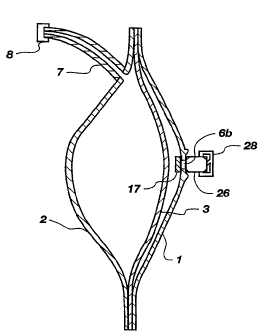
Figure 3 is a schematical representation of a gas generating device employ-
ing a galvanic cell, gas generator, typically generating hydrogen gas.
External gas
chamber shell 1 is comprised of a material which has some minimal hydrogen
permeability but which is sufficiently Iow to obtain acceptable efficiency.
The shell
1 has very low moisture vapor permeability, a suitable gas chamber shell is
some-
what spherical with flanges and is preferably rigid. The liquid chamber shell
2 is
also somewhat spherical and is hermetically attached at the perimeter to the
perime-
ter of said gas chamber shell with a flexible diaphragm 3 therebetween. Said
liquid
shell 2 is comprised of a material which is chemically compatible with the
liquid to
be dispensed and which has low permeability to the liquid to be dispensed and
is
preferably is rigid. Flexible diaphragm 3 is comprised of a material with low
hydrogen permeability, eg. EVOH or metallized polymer films. Initially the gas
IS chamber 5, which is the space between said gas chamber shell l and said
flexible
diaphragm 3 has virtually no volume. Conversely, the liquid chamber 4 which is
the
space between said liquid chamber shell 2 and flexible diaphragm 3, is filled
with
the liquid to be dispensed. Liquid chamber 4 has an outlet through which
liquid may
flow when pressurized. In the embodiment illustrated, a tube 7 and plug 8 are
attached to said liquid chamber outlet. Plug 8 is removed at the time of
activation.
The gas generation cell may be one of those depicted in Figures I-2. The
gas generator shown generally as 26 is sealed to the gas chamber shell 1. A
gas
inlet port 6b in said gas chamber shell is concentric with gas outlet port 6a
in said
can. In the embodiment shown in this figure, an intermediate moisture harrier
is
located between said gas inlet port and gas outlet port. The activation clip
is shown
generally as 28. To activate the gas generator, an activation clip is slid
onto the
generator. At the time of activation said clip is slid so that the circuit is
completed.
As the circuit is completed, hydrogen gas is generated at a rate which is
directly
proportional to the electrical current flowing through the circuit. As the gas
is
generated, it flows into the gas chamber and exerts a force against the
flexible
diaphragm which in turn forces the fluid to flow through the liquid port and
outlet
tube. The rate of flow of the fluid is affected by the ohmic resistance of
said
resistor 25. The rate is higher if the resistance is smaller.
CA 02234074 1998-04-06
WO 97/13007 PCT/US96/15375
-23-
Figures 4A-E show different locations where an intermediate moisture
burner 17 may be located relative to the gas chamber and gas generator compo-
nents. If an intermediate moisture barrier is utilized as shown in Figurc;s 4A-
E, then
the gas chamber shell 1 does not require very low moisture permeability
properties.
The gas generator as a unit is labeled generally as 26 with seal 27 to the gas
chamber shell 1.
In Figure 4A the intermediate moisture barrier 17 is positioned on the
interior of the gas chamber shell i over the gas inlet port 6b. A barrier in
this
location may be permanent or releasable.
In Figure 4B the intermediate moisture barrier 17 is positioned 'between said
gas outlet port 6a of the gas generator and gas inlet port 6b of the gas
chamber
shell. In this position the effective moisture permeation area during storage
is the
area of said gas outlet port which may be very small.
Figure 4C shows the position of intermediate moisture burner 17 after the
device has been activated and pressure pushes the barrier away from the can 9
such
that the effective hydrogen permeation area increases from that of the gas
outlet port
6a to that of the Larger gas inlet port 6b. This provides a better situation
for
controlling moisture loss during storage but permitting adequate flow of
hydrogen
during operation.
Figure 4D shows that the intermediate moisture barrier 17 may also be
placed inside said gas generator. In this location the effective permeation
area
before and after activation is that of the gas outlet port.
Figure 4E also shows the intermediate moisture barrier 17 place~,d inside said
gas generator but in this case, diffusion mesh 16 is placed against said can 9
and
said intermediate moisture burner 17 is between said hydrophobic banner 15 and
the
mesh 16. In this case the effective permeation area before and after
activation is
nearly the area of said can.
Figure 4F shows an intermediate moisture burner which released under the
pressure generated from the gas generating device. Thus the benefit of
moisture
retention during storage was realized without any hindrance to the flow of
hydrogen
from the gas generating cell during operation.
The moisture barrier useful in the structure illustrated in Figures 4A through
4F is one in which water vapor permeation is minimal, preferably approaching
zero,
CA 02234074 1998-04-06
WO 97/13007 PCT/US96/15375
-24-
while hydrogen gas permeation is sufficiently high such that hydrogen
permeates
through the barrier substantially as rapidly as it is formed during operation
of the
gas (hydrogen) generator. The rate of fluid delivery ultimately is controlled
by the
rate of gas generation. Thus, it is preferred that the moisture vapor barrier
has a
hydrogen gas permeability which does not retard the rate of hydrogen passage
into
the gas chamber below the rate of hydrogen generation. Although the gas perme-
ability through the moisture vapor barrier could be used as the rate
controller, such
a system is not preferred.
Figure 5 is a schematical representation of an embodiment of the invention
where an electrochemical fluid delivery device with a syringe type fluid
container.
The gas generator as a unit is labeled 26 with seal 27 and activation clip 28.
Fluid
to be dispensed 4 is contained in a syringe body 30. The gas generator is
attached to
an adapter 31 constructed of heavy plastic which is fitted into said syringe
body. A
piston 33 constructed of heavy plastic or metal is placed into the syringe
body. Said
piston has one or more seal rings 34 which may be O-rings or U-rings made of
elastomer. The U-ring is superior for this application since the rate of fluid
delivery
is affected less by deviations of the syringe body inner diameter. Polysulfide
rubber,
nitrite rubber, polyurethane, and FEP rubber, butyl rubber are among the
better
materials for the seal since they have relatively low hydrogen permeability.
Nitrite
rubber or Buna N is particularly suitable because it is pliable enough to make
a
good seal against the syringe body. A threaded insert 35 is provided so that a
removable handle (not shown) with female thread can be utilized to drive the
piston
manually stroke the piston for the purpose of filling the fluid 4 into the
syringe.
Said adapter 31 is formed in a manner such that said threaded insert 35 of
said
piston 33 fits into a pocket, minimizing headspace between said adapter and
piston.
A fluid delivery tip 36 may be connected to a tube set or hypodermic needle.
An
intermediate moisture barner in this embodiment was placed between said gas
generating cell 26 and adapter gas inlet port 6b.
Figure 6 is a schematical representation of an embodiment of the invention
where the fluid delivery device has a non-permeable gas chamber shell 40 with
a
permeation window 41. A film 42, which is somewhat permeable to hydrogen to
vent inadvertent hydrogen generated during storage but which will inhibit
moisture
loss, is sealed over the window either on the interior of the shell, as shown,
or on
CA 02234074 1998-04-06
WO 97/13007 PCT/US~96/15375
-25-
the exterior. In this embodiment the gas chamber shell is crimped over' the
flexible
diaphragm and liquid chamber shell in the manner of the beverage can packaging
industry.
Figure 7 is a schematical representation of an embodiment of the invention
where a battery is utilized to drive the gas generating cell to achieve
hiigher or more
stable fluid delivery rates. This embodiment is shown to be utilized with a
syringe.
A housing 50 contains the gas generating cell 26 and a button cell battery 51
which
is placed such that the positive battery terminal contacts the cap 10 of ;said
gas
generating cell. In this case a commercially available switch is utilized
instead of
the activation clip. Contacts 53 and 54 are in electrical communication with
the
switch and a resistor {not shown) to form an electrical circuit with the
battery and
gas generating cell. In this figure the device is shown with the piston 33
already
pushed away from said housing 50 by the generated hydrogen.
Figure 8A is a schematical representation of an embodiment of the invention
where an electrochemical gas generator has liquid and solid components
isolated
from each other before activation. The figure also represents, with some
modifica-
tion, the embodiment of the invention which is a corrosion type gas generator.
Construction is similar to the embodiment shown in Figure 1. Cylindrical can
9, gas
outlet ports) 6a, gas diffusion mesh 16, sealing layer 15a and second
ihydrophobic,
micro-porous layer 15b perform the same functions as in Figure 2. Current
collector
/ catalyst Layer 14, and separator are in the same relative positions and.
serve the
same functions as in Figure 2. Adjacent to the separator and fitted secure
against the
can wall is an electronically insulating cylindrical anode grommet 60 which
open at
both ends. Fitted against said separator and within said anode grommet opening
is
the active anode metal 61. Said active metal may be a powder pressed into a
porous
pellet or may be a solid piece but must have access holes such that
electrolyte may
pass through to the separator. The active anode metal pellet or piece has a
void
. space 62. Divider 63 is formed of a material with low moisture permeability
and
fits against said anode grommet and is sealed thereto. Breaking structure 64
is either
- 30 formed with said divider 63 or is a separate part. Electronically
conductive flexible
cap 67 is fitted into the cap grommet 63. The flexible cap / grommet assembly
fits
against said divider 63 and is sealed thereto. The can is crimped at the. open
perimeter over said cap grommet to hold said assembly in place and to compress
the
CA 02234074 1998-04-06
WO 97/13007 PCT/US96/15375
-26-
internal seal joints. Within said flexible cap is stored the electrolyte 68
with inactive
but electronically conductive powder such as graphite or carbon black. The
activa-
tion clip consisting of contact ring 21, electronically insulating cylinder
22, elec-
tronically conductive contact cup 23, contact indent, and resistor 25 have the
same
configuration and serve the same functions as in Figure 1. In addition, when
said
activation clip is slid to complete the circuit, said contact indent presses
against
flexible cap 67 such that said cap presses against said breaking structure 64
which
breaks or shears the divider 63 at break zone 65. As said divider is broken,
electrolyte and electronically conductive powder flow into void 62 and into
the
pores within said anode metal 61. As this occurs, the gas generator becomes
functional and begins to produce hydrogen galvanically at a rate proportional
to the
current in the completed circuit. Since the electrolyte is separate from the
active
metal during storage, there is no inadvertent hydrogen produced during
storage,
thus the gas chamber shell 1 can be constructed of a completely impermeable
material. Also there is negligible moisture loss or gain during storage.
Figure 8B shows the gas generating device illustrated in Figure 8A after it
has been activated. The divider 63 has been perforated at break zone 65. Fluid
68
has been forced into contact with active metal 61.
A corrosion type gas generator can be constructed identical to the gas
generating cell in Figure 8A and 8B except said current collector l catalyst
layer 14,
and separator 13 may be omitted. Also the electronically conductive powder in
said
electrolyte can be omitted since the active anode metal does not require
electrical
continuity with said cap. Corrosion reducing agents would either be added to
the
electrolyte or to the active metal anode to achieve a particular fluid
delivery rate.
Also said resistor in the activation cap can be omitted. The contact ring 2I,
insulat-
ing cylinder 22, conductive cup 23, and indent 24 can be integrated into a
single
part formed of a material which is either conductive or insulating. Such a
corrosion
type gas generating device can also be utilized with a syringe type
embodiment.
Figure 9 is a cross-sectional view of an embodiment of the gas generating
portion of the invention which is constructed similar to a dry cell battery
but where
depolarizer (manganese oxide or dioxide) and separator are omitted from the
construction. Cylindrical can 90 is formed of the electroactive metal anode
material
such as zinc, aluminum or magnesium or alloys thereof. The can is closed at
one
CA 02234074 1998-04-06
WO 97/13007 PCT/CJS96/15375
-27-
end. Electronically insulating washer 91 is placed inside the can against: the
closed
end. Electronically porous rod 92 serves as cathode and passageway for the
generat-
ed hydrogen to exit the cell. Suitable material for the rod would be porous
carbon
or graphite, particularly carbon or graphite which has some electrocatalytic
coating
on the surface. Said rod is held concentrically in said can by an insulating
washer
93 with a hole through which the rod passes. The can is filled with aqueous
electrolyte 94 which may be either alkaline or non-alkaline such as in the
cell
illustrated in Figure 1. If the electrolyte is alkaline, examples of suitable
electro-
catalytic coatings on said rod 92 include nickel or Raney nickel. If the
.electrolyte is
non-alkaline, examples of suitable electxocatalytic coatings on said rod '92
include
ruthenium, iridium, platinum or combinations thereof. A gas impermeable,
electron-
ically conductive tube 95 such as metal tubing is fitted over the end of said
rod 92
so that generated gas can flow axially and not escape radiaily into the
environment.
A hydrogen permeable intermediate moisture barrier 96 is placed over 'the end
of
said rod 92. The moisture burner may be permanent, releasable or rupt:urable
so
that moisture loss during storage is minimal but hydrogen may pass through the
end
of the rod at a sufficient rate fox the intended application. A sealing
material 97
such as pitch is placed adjacent to insulating washer 93 to prevent escape of
electrolyte or generated gas. Cathode contact washer 98 electronically
communicates
with tube 95 and covers sealing material 97. Anode contact washer
electronically
communicates with the electroactive metal can 90. Said cathode washes' and
anode
washer are crimped to electronically insulating cylindrical jacket 100. The
jacket
may be comprised of several layers as is common with dry cell batteries. For
example, the jacket may include layers of polymer films and paper.
To activate the gas generator, an electrical circuit is completed L~etween the
cathode contact washer 98 and anode contact washer 99. The electrical circuit
may
include a resistor, switch, and optionally a D.C. power source such as a
battery. If
a D.C. power source is utilized, the negative pole communicates with i:he
cathode
contact washer and the positive pole communicates with the anode contact
washer.
As current is passed, hydrogen forms at the rod 92. As hydrogen is generated,
it
flows through the rod axially toward the intermediate moisture burner 96,
through
which it passes into the gas chamber of a fluid deliver reservoir which is not
shown.
CA 02234074 1998-04-06
WO 97/13007 PCT/US96/15375
-28-
Figure l0A is a schematical representation of fluid delivery embodiment
utilizing the type of gas generator shown in Figure 9 which is depicted
generally as
110. Gas chamber 111 and liquid chamber 112 share a flexible diaphragm I13.
Liquid chamber is connected to liquid flow tube 114. Electrical circuit 115
includes
resistor 116 and pull tab switch 117. When pull tab switch 117 is removed, the
electrical circuit is completed and generated hydrogen enters the gas chamber
111.
Flexible diaphragm 113 moves under the increase in pressure to cause fluid to
flow
from liquid chamber 112 into said liquid flow tube.
Figures lOB is a schematical representation of fluid delivery embodiment
utilizing the type of gas generator shown in Figure 9 which depicted generally
as
110. Tn this embodiment, a commercially available battery is utilized to
enable
operation at a higher fluid delivery rate or to enable the utilization of a
larger
resistor in the circuit for more stable delivery. Both gas generator 110 and
battery
120 are contained in housing 121. During activation, contact 122 communicates
with the anode contact of the gas generator and switch 123. Contact 124
comrnuni-
sates with the positive terminal of battery 120 and said switch. Contact 125a
communicates with the negative terminal of said battery 120 and resistor 12b.
Contact 125b communicates with cathode contact of said gas generator 110 and
the
resistor. As current passes through the circuit, gas flows into bellows 128.
As
bellows expand, liquid 129 is pushed from liquid chamber 127 into flow tube
130.
Figure l I shows an embodiment of the invention where the hydrogen is
dissipated continuously as it is produced. This embodiment can be utilized if
the
liquid is to be dispensed so that it can vaporize into the environment. Such
liquids
include some fragrances and insect repellants or insecticides. Liquid 7I is
contained
2S within syringe container 70. Hydrogen gas generator / activation clip
assembly is
sealed to fixture 75 which fits into the base of said liquid container 70. A
hydrogen
permeable film 72 such as OPP or PFA may be utilized to prevent the liquid
from
entering the gas inlet part 76. Micro-porous film covers the liquid vapor exit
port
73. As hydrogen gas is generated, it passes directly through the liquid to be
dispensed. The hydrogen becomes saturated with the liquid before it passes
through
said micro porous film at the vapor exit port.
Figure 12 shows a plot of volume liquid dispensed versus time utilizing a
galvanic gas generating cell and reservoir similar to the embodiment of the
inven-
CA 02234074 1998-04-06
WO 97lI3007 1'CT/US96l15375
_29_
tion shown in Figure 2. The gas generation cells were constructed similar to
zinc/air
batteries in that they had an amalgamated zinc gel anode in an alkaline
electrolyte.
The cathode was a nickel expanded metal screen to which PTFE coated! carbon
was
pressed. A porous fluoropolymer hydrophobic barner 15b was pressed to the gas
side of the cathode mesh 14 and a second porous fluoropolymer hydrophobic
sealing
layer 15a was placed between barrier 15b and a nonwoven polypropylene gas
distribution mesh 16 which was placed between the cathode and the exit ports
6a of
the can 9. An intermediate 0.00254 centimeters (0.001 inch) thick Mylar~
moisture
barner 17 covered the gas flow holes as shown in Figure 4B and such that the
gas
permeated through the moisture barrier before entering the gas chamber. As the
gas
generated increased the pressure behind the intermediate moisture barrier 17,
the
moisture barrier flexed, increasing the effective permeation area as shown in
Figure
4C. The gas chamber 1 was constructed substantially of a PAN based material
Barex~ which was 0.03175 centimeters {0.0125 inches) thick and had
approximately
10 cma area, the Barex~ also had coating layers which facilitated forming a
hermetic
seal 23. The flexible diaphragm 3 was constructed of EVOH film of 0.00762
centimeters (0.003 inch) thickness. A non aqueous fluid was dispensed which
had a
viscosity of about 1 centipoise. The gas generating cells where operated
galvanically
with either a 4000 ohm or 6000 ohm resistor 20 in the circuit between anode
and
cathode. Two curves are shown indicating the volumes of fluid delivered with
respect to time over a period of several days.
The data plotted in figure 13 is from Jacus's U.S. Patent 5,034,291.
Hydrogen gas evolves from a mixture of zinc containing 150 ppm indium and
various amounts of additives when the zinc has been mixed with electrolyte
consist-
ing of 38 weight i~ potassium hydroxide, 3 weight ~ zinc oxide and water. The
additives in this case were mercury and or aluminum potassium sulfate.. The
plot
shows that rate of hydrogen generated is at a nearly constant rate, and that
the rate
is affected by the type and level of additives in the mix. These types of
hydrogen
generation curves are possible utilizing the embodiment of the invention as
shown in
Figure 6a&b. This embodiment is capable of very long shelf life.
Figure 14 shows the ratio of liquid volume pumped versus the volume of
hydrogen gas generated (or efficiency) for bladder systems composed of various
monolayer materials where the area is held constant at 10 cm2 and the material
CA 02234074 1998-04-06
WO 97/13007 PCT/US96/15375
-30-
thickness is held constant at 0.0381 centimeters (0.015 inches). The plot is
efficien-
cy versus hydrogen permeation coefficient which has been multiplied by 1013,
where
the coefficient units are cc-cm/cm2-s-Pa. Curves representing rates of 1, 0.2
and
0.04 cc's per day are shown. The efficiency is higher when the hydrogen
permeabil-
ity is lower, also as dispensing rates are lower, efficiency is lower because
of the .
increased gas loss over time.
Figure 15 shows the time in days at 25°C required for the hydrogen
concen-
tration inside a gas chamber bladder to drop to less than 10 % once the device
becomes inactive assuming that the starting concentration is 100 % and that
the gas
chamber shell is constructed of various monolayer materials of either 0.00254
crn
(0.001 inches) or 0.0381 crn (0.015 inches).
Figure 16 shows the relative concentrations of hydrogen and air versus the
relative time until the hydrogen concentration reaches 10 % . This plot
assumes that
the shell is constructed of PET but the plot is very similar for other
materials.
Figure i7a shows hydrogen concentration for bladder systems composed of
various monolayer materials possessing various nitrogen permeation constants,
and
where the area is varied from 1- 100 cm2 . The material thickness is held
constant
at 0.0381 centimeters {0.015 inches) and the fluid delivery rate is held
constant at
0.2 cc per day. The plot is hydrogen concentration versus inverse nitrogen
perme-
ation coefficient which has been multiplied by 1013, where the coefficient
units are
cc-cm/cm2 -s-Pa. Curves representing 1, 10 and 100 cm2 area are shown.
Similarly, figure 17b shows hydrogen concentration for bladder systems
composed of various monolayer materials possessing various nitrogen permeation
constants, and where the fluid delivery rate is varied . The material
thickness is
held constant at 0.0381 centimeters (0.015 inches) arid the area at 10 cma.
The plot
is hydrogen concentration versus inverse nitrogen permeation coefficient which
has
been multiplied by 1013, where the coefficient units are cc-cm/cm2 -s-Pa.
Curves
representing 0.04, 0.2 and I cc per day fluid delivery rate are shown.
Figure 18 shows the benefit of utilizing an intermediate moisture barrier
between an electrochemical gas generating device and the gas chamber. The gas
generator is a zinc H2 generator with dhulin electrolyte. The plot shows
liquid
volume dispensed of devices operated at different rates, with and without the
intermediate moisture barner. The gas generation cells and gas chamber /
liquid
CA 02234074 1998-04-06
WO 97/13007 PCT/US96/15375
-31-
chamber reservoir construction and fluid dispensed were the same as described
for
Figure 12.
Figure 19 shows a plot of fluid delivery volume versus time of a device as
shown schematically in Figure 7. The plot shows the benefits of driving the
gas
delivery cell with a battery. The results shown are for a zinc HZ generator
with a
syringe.
Example 1: A device was designed such that the gas generator was of the
type disclosed in Winsel's U.S. Patent 5,242,565. The gas generator was sized
such
that it was similar to a 675 zinc/air battery. The device needed to deliver 10
cc's of
fluid at 1 atmosphere pressure. The gas chamber had 10 cm2 area and could have
a
maximum thickness of 0.0381 centimeters (0.015 inches). Moisture loss through
the
flexible diaphragm and out through the liquid chamber shell was to be
considered
negligible due to low solubility in the liquid. The shelf life requirement was
2 years
in 37.8°C. (100°F.) at 20% relative humidity or 90~ humidity.
The alkaline
electrolyte used in Winsel's gas generating cell would typically have ara
moisture
equilibrium with environment at 60% relative humidity. That is, at humilities
above
60 ib , the electrolyte would absorb moisture from the environment; at
llumidities
below 60 °b , the electrolyte would lose moisture to the environment.
Such an
assumption is true for many electrolytes utilized in the battery industry. The
design
criteria called for SO 9& excess zinc than theoretical and to insure that the
device
would operate at a constant rate of 0.2 cc per day, the assumption is made
that less
than 20 °b volume change of the gas generating cell's constituents
could be permit-
ted. In the battery industry the assumption is typically made that less tlhan
15 ro
volume change can be permitted. Winsei provides in his gas generating; cells,
absorbent materials to provide moisture necessary to make-up the water
consumed
in the reaction:
Zn + H20 -> Zn0 + H2
' 30
Also moisture carried into the gas chamber must be considered. However, Winsel
neglects the overwhelming loss of moisture which may occur during storage or
during the life of the pumping device which can far exceed any moisture
consumed
CA 02234074 1998-04-06
WO 97/13007 PCT/US96/15375
-32-
in reaction or transported to the gas chamber. Winsel also neglects the
detrimental
condition which would occur if an initially full gas generating cell absorbed
appreciable moisture in a high humidity environment during storage or during
the
life of the product. The gas generating cell may leak electrolyte into the gas
chamber and flood the porous portions of the gas generating cell where
hydrogen is
intend to flow away from the site of hydrogen evolution. Such a condition has
a
detrimental impact on gas generating cell performance. The volume available in
the
gas generating cell exclusive of the hydrogen evolving cathode in 675 battery
hardware is approximately 0.330 cc. If PVDC is considered for the shell
because
of its low moisture permeability property, from Figure 14 it can be determined
that
at 0.2 cc per day dispensing rate that the efficiency will be about 95 9b .
Thus, the
required zinc is 42.2 mg or 0.0059 cc leaving 0.324 cc for electrolyte
assuming that
the gas generating cell is completely filled. If the absorbing members
recommend
by Winsel are utilized, then only a fraction of 0.324 cc would be available
for
electrolyte. But assuming the larger amount of 0.324 cc, approximately 302 mg
water would be contained. Of that 302 mg water, 7.7 mg water will be consumed
in
the gas generating cell reactions, and 0.1 rng water will be transported into
the fully
expanded gas chamber assuming that the gas chamber equilibrate with the gas
generating cell electrolyte at standard temperature and pressure. To insure
that the
volume change of the gas generating cell is less than 20 % , the moisture lost
to the
environment though the gas chamber shell or other pathways must be less than
68
mg. I~owever, the moisture loss during two year storage at 37.8°C.
(100°F.) and
20 °~ relative humidity would be approximately 84 mg. If the shell were
OPP,
HDPE, or PTFE, then the loss would be about 100 mg. If the shell were PET then
the loss approximately 320 mg. Only PCTFE based materials such as Ilalar~ or
Acla~ or metallized films would satisfy the criteria for 2 year shelf life.
These
materials may be prohibitively expensive for some applications.
Example 2: Under the same design criteria as described in Example 1, an
alternative which would increase the possibilities for gas chamber shell
materials is
to utilize an intermediate seal. If a moisture barner is utilized as shown in
Figures
4B or 4D and if the area of the gas outlet ports amount to 0.009 square
centimeters
and if the moisture barner is 0.00254 centimeters (0.001 inch) thick, then the
moisture Loss during the storage period under the conditions described above
would
CA 02234074 1998-04-06
WO 97/I3007 PCT/US96/I5375
-33-
be Less than 5 mg for a Large number of readily available materials including
OPP,
HDPE, LDPE, and PET, other materials which would Limit moisture loss to less
than 5 mg would include PFA, FEP, PTFE, PVDC, PCTFE or Acla~', PCTFE/PE
or Halal or metallized films. These materials would also permit permeation of
inadvertent hydrogen produced during storage. All of the materials would
reduce
start-up delay due to oxygen which may be in the headspace between in the gas
chamber at the time of activation to varying degrees. If a film were utilized
which
was metallized with palladium, iron/titanium alloy, or nickel, there would be
virtually no start-up delay. PET, PCTFE or Acla~ or PCTFE/PE or Halal have
low oxygen permeability but have high enough hydrogen permeability such that
permanent intermediate moisture barners could be utilized as shown in Figures
4B
and 4C and also provide adequate barner to moisture loss for the storage
criteria.
Example 3: Under the same design criteria as described in Example 1 a non
permeable gas chamber shell could be utilized constructed from metal with a
window covered with a material which would permit inadvertent hydrogen generat-
ed during storage but inhibit moisture permeation. If the window has area of
0.0581
square centimeters (0.009 square inches), then the same materials suit<~tble
for the
intermediate moisture burner in Example 2 would be suitable for covaring the
window assuming 0.00254 centimeters {0.001 inch) thickness.
Example 4: Under the same design criteria as described in Example 1 an
additional criteria is added where the gas chamber is to have a hydrogen
concentra-
tion less than 10 % within 10 days after the device stops generating hydrogen.
From
Figure 15 one can determine that the materials PFA, OPP, PTFE, FEP, poly-
carbonate or Lexan~, LDPE, or LLDPE, ETFE, and PCTFE/PE or f3:alar~ would
be candidates to meet the criteria. Suppose LDPE or T r nPE are considered
because they are readily available and Halar~ is considered because of its low
moisture permeability properties. The hydrogen permeability of typical
commercial
films of these materials is 7.4 x 10-'3 LDPE and T .T -nPE and 4.0 x 10u3 cc-
cm/sqcm-s-Pa for Haiar~. From Figure 14 it can be determined that with 10
square
centimeters area and 0.0381 centimeters (0.015 inch) thickness, the fluid
delivery
devices would operate at approximately 20 % and 30 ~ efficiency respc;ctiveiy.
Since
the moisture permeability of LDPE is high, an intermediate moisture barrier
would
be required to insure moisture retention during storage at low humidity or to
CA 02234074 1998-04-06
WO 97/13007 PCTlUS96l15375
-34-
prevent moisture gain in high humidifies. A gas generator sized like the 675
battery
is large enough to generate the extra hydrogen required to operate at either
20 % or
30 % if the volume to be delivered is 10 cc. Since more zinc must be utilized
and
more water consumed in the reaction, less water can be lost to the environment
during storage. In the case of 20 % efficiency, the maximum moisture loss
would be ,
48 rng and in the case of 30 % efficiency the maximum Loss would be 56 mg.
With
PCTFE/PE or Halal the moisture loss during 2 years at 37.8°C.
(100°F.) and
20 % humidity would be limited to 9 mg and thus be acceptable without an
interme-
diate moisture barrier. Another acceptable candidate would be a combination of
materials such as a 0.0076 centimeters (0.003 inch) layer of Halar~' and
0.0305
centimeters (0.012 inch) layer of LDPE or T T nPE. The materials could be
laminat-
ed or castrated. The Layer of Halal would provide adequate moisture barner,
limiting the moisture loss to 45 mg so that an intermediate moisture barrier
would
not be required and the final structure would meet the requirement that the
gas
chamber would be < 10 % hydrogen within 10 days after the device stops
generating
hydrogen.
These examples illustrate the importance of knowing the materials of
construction since they dramatically affect both shelf life, and ultimate
operating
efficiency which in turn affects the amount of active materials which must be
included in the gas generator for a particular application.