Note: Descriptions are shown in the official language in which they were submitted.
CA 02234084 1998-04-06
W O 97/13110 PCT~US96/13248
Title: APPARATUS AND METHOD FOR DRYING OR CURING WEB
MATERIALS AND COATINGS
Field of the Invention
The present invention relates generally, as is indicated, to apparatus
and method for drying or curing web materials and coatings, and, more
particularly, to the combined usage of electromagnetic energy and flowing
fluid for drying and/or curing.
Background
In the process of making a web, such as a paper web or a web made
of a plastic or plastic-like material, the web is moved through a dryer in
which the web itself is dried or cured and/or a coating or other material
which has been applied to, imbibed in, etc. the web material is to be dried
or cured. Drying usually is referred to as the removing of moisture, such as
water, solvent or another ingredient, e.g., by evaporation, from the web,
coating, etc. Curing usually refers to the carrying out of a chemical
reaction. However, drying and curing are used herein in the broadest sense;
and for brevity the term drying will be used below inclusive also of curing.
Also, for brevity reference herein to drying a web includes drying the web
itself and/or a coating thereof.
The line speed at which emulsions, which are coated on a web, can
be dried during a web manufacturing process, for example, is limited by how
quickly water can be removed from the emulsion coating (drying flux) and
the length of the dryer apparatus (dwell time of the web in the dryer). Line
speed increases are limited by drying flux capacity of the dryer to dry the
web without damaging the web. Line speed increases could be achieved if
the dryer were lengthened to provide the required dwell time to obtain
desired drying. There are similar considerations for curing a web. However,
there are some disadvantages in making a dryer longer, such as the need to
CA 02234084 1998-04-06
W O 97/13110 PCTAUS96/13248
increase the number of zones in the dryer, which adds to the size,
complexity, difficulty of control, and expense of the dryer, additional air
handling equipment, and a longer web path in the dryer apparatus. Also, a
longer unsupported span of web in a dryer, between dryers or drying zones,
etc. can increase the risk of web breaks, snags, and/or other web handling
problems; and, therefore, the risk of loss of material and time delays due to
shutdowns are increased. It would be desirable to increase the capacity of
a web dryer apparatus by running that apparatus at faster line speeds
without increasing the dryer length. Accordingly, and consistent with the
invention as is described in detail below, it would be desirable to provide an
emulsion drying method and apparatus in which the drying flux capacity is
increased so that emulsion coatings can be dried in a shorter dwell time in
the dryer.
Some prior web dryers have used an air flotation technique to dry a
web passing through the dryer. The air flotation oven dryer apparatus
usually includes several air bars or nozzles located, respectively, facing
opposite surfaces of the web. The web is moved along its path through the
dryer, and heated air is blown toward the surfaces of the web by respective
air bars. The air usually is heated to facilitate drying the web.
Blowing heated air toward the surfaces of a web, though, has been
found to be relatively inefficient to dry a web. For example, the process of
heating air is a relatively inefficient one, and the transferring of thermal
energy to the web by air also is relatively inefficient. Also, the enthalpy of
air is relatively low. However, it is desirable to heat the web to increase the
drying flux and, therefore, the rate at which the material actually dries.
Several techniques have been used in the past to try to improve the
drying flux and, therefore, to reduce the time required to dry a web. One
technique was to design the air bars to direct air flow toward the web in a
manner that creates an air foil effect to increase the wiping of the flowing
air fluid against the web. Another technique was to direct the air flow from
CA 02234084 1998-04-06
W O 97/13110 PCTAJS96/13248
the air bars toward the web in several directions in order to create a
somewhat turbulent flow at the web to increase the wiping of the air against
the web and the transfer of thermal energy to the web. The air bars usually
had to be relatively close to each other to get sufficient thermal energy
transfer for drying, and the air bars themselves were relatively narrow in
length dimension (direction of belt travel) to concentrate hot air toward/at
the web without losin~ heat to the surrounding environment. The larger the
number of air bars, though, the more expensive is such a prior air floatation
dryer, and the more distortions are applied to the web, which possibly could
cause damage to the web. Also, when the air bars are spaced more closely,
the air flow is limited because there must be sufficient space to remove the
exhaust air. Still further, with the air bars positioned close to each other,
there may not be adequate room to locate electrodes for developing and
applying RF field to the web.
1 5 Another disadvantage to the drying of a coating, such as an emulsion,
on a web using the air flotation oven technique is that the coating surface
tends to dry faster and to become hotter than the subsurface coating
material, and the dry surface may become fused and/or difficult for
subsurface moisture to penetrate and to escape to the external environment.
Therefore, careful consideration must be given to controlling drying to take
into account the moisture concentration profile in the coating material to
achieve drying of the entire coating, not just the surface portion thereof.
Such consideration may result in the reduction of the temperature of the air
directed to the web, but the reduced temperature results in a smaller drying
flux and reduced drying rate, which can slow the drying process or can
require an increase in the path length of the web in the dryer.
Another technique for dryin~ a coating on a paper web includes the
directing of a stray field of radio frequency (hereafter abbreviated "RF")
electromagnetic energy provided, for example, at from about 10 MHz to
about 100 MHz to the web. Stray field electrodes are used to provide the
CA 02234084 1998-04-06
W O 97/13110 PCTAJS96/132~8
stray field which heats the coating to cause drying. The web is supported
relative to the electrodes by a flow of hot air which also removes steam
clouds produced by the high-frequency RF energy stray field drying process.
The air flow is provided via air bars which also may serve as electrodes to
provide the RF stray field. However, a problem that can occur using such
stray field drying process is blistering of the coating, which can occur when
the coating becomes too hot while drying as it is exposed to the high-
frequency electromagnetic energy and hot air. A web with a blistered
coating usually is an unacceptable product. It would be desirable to use RF
drying while avoiding such blistering or other heat damage to a web.
Blistering is one example of a defect caused in the coating during
drying. Blistering may occur for several reasons. For example, if the
temperature of the coating is raised too high or too fast, blistering may
occur; or it may occur due to the formation of a skin on the coating which
blocks release of subsurface moisture. It wouid be desirable to dry a web
while minimizing defects, such as defects in the coating, e.g., blistering, and
especially to effect such relatively defect-free drying at a relatively fast rate.
The invention is described below by way of example with respect to
the drying of an emulsion type of coating on a paper web. In the drying
process moisture, e.g., water, contained in the emulsion is removed from
the emulsion. The result may be substantially all moisture being removed
or only some of the moisture being removed, depending on the product. It
will be appreciated that the moisture also may be removed from a coating
that is other than an emulsion and that the moisture may ~be removed from
the web itself. The coating may be on one or both surfaces of the web or
the coating may be imbibed or otherwise in a sense absorbed in or carried
by the web. In one example the web is paper, but it will be appreciated that
the web may be of another material, such as a plastic or plastic-like material.
The ingredient removed during the drying process may be a material other
than or in addition to water. One example is a solvent. Another example
CA 02234084 1998-04-06
W O 97/13110 PCTAJS96/13248
is a carrier fluid. Also, the invention may be used to cure a material rather
~ than or in addition to the drying of the material.
The invention may be used to provide air flow or the flow of some
other fluid with respect to the web- ~he other fluid may be a gas or a liquid,
depending on circumstances, such as characteristics of the web and/or
coating, whether the gas is to parti',ipate in a chemical reaction, such as
part of the curing process, etc, For brevity, thou9h, the fluid flow will be
described below by way of example as an air flow.
The invention directs electromagnetic energy with respect to the web.
The electromagnetic energy may be in the radio frequency (RF) spectrum or
wavelength range. If desired, the electromagnetic energy may be in another
range, such as that of microwave energy. Reference herein to RF energy
includes all such electromagnet!c ener~y capable of contributing to drying
or curing as is described herein. Adlditionally, the electromagnetic energy
1~ may be directed to the web as a stray field, through field or both.
With the foregoing in mind, th~n, it would be desirable to increase the
speed of the apparatus and process for drying a web to increase the web
throughput while avoiding damage, such as that due to blistering. It also
would be desirable to be able to o~ltimize the travel speed of a web in a
dryer to reduce time spent in the dr~,~er or in drying the web and to reduce
the energy required to dry the web. It also would be desirable to be able to
detect conditions related to the drying of a web to achieve the foregoing to
facilitate accommodating webs and/or coatings of different materials, size
or other parameters, etc.
Conventional air floatation dryers use heated air both to heat the web
and/or coating and to remove moisture emitted by the web and/or coating;
thus, prior dryers use the heated a~ to provide both heat transfer and mass
transfer. The present invention uses RF energy for heating and can use the
air flow for mass transfer or for both heat transfer and mass transfer.
CA 02234084 1998-04-06
W O 97/13110 PCTAUS96/13248
Summarv
According to one aspect of the invention, a method of drying and/or
curing (reference to drying also, additionally or alternatively, may include
curing as may be appropriate to the material being dried andlor cured) a web
including a coating thereof (reference to drying a web may include the
drying of a coating thereof drying of the web itself or both) includes
directing a web along a sinusoidal path, the directing including directing a
fluid flow (the fluid flow sometimes will be referred to as an air flow, but it
will be appreciated that such reference rnay include the possibility that the
fluid flow is a gas or liquid that is other than or is in addition to air) toward
one surface of a web at two locations to urge the web in one direction and
directing fluid flow toward an opposite surface of the web at a location
between a pair of the first-mentioned locations to urge the web in a direction
opposite such one direction, directing radio frequency (hereinafter
sometimes referred to as "RF") energy toward the web, and controlling at
least one of tension on the web and fluid flow rate(s) thereby to control the
amplitude characteristic of the sinusoidal path and, thus, the direction in
which and/or extent to which the RF energy impinges on the web.
Sinusoidal path may meari a path that may be generally of a sine
wave shape or more broadly is an undulating, wavy, up and down, back and
forth, etc. path. Also, the fluid flow is mentioned as directed at a surface
of the web; the actual surfaces may not necessarily be opposite ones
provided the sinusoidal path is obtained when desired.
Another aspect relates to apparatus for drying a web-including means
for directing a web along a sinusoidal path, the directing means including
means for directing air flow toward one surface of the web at two locations
to urge the web in one direction and means for directing air flow toward an
opposite surface of the web at a location between a pair of the first-
mentioned locations to urge the web in a direction opposite such one
direction, means for directing RF energy toward the web, and means for
CA 02234084 1998-04-06
W O 97/13110 PCTnUS96/13248
controlling at least one of tension on the web and air flow thereby to control
the amplitude characteristic of the sinusoidal path and, thus, the direction
in which the RF energy impinges on the web.
According to another aspect, a method of drying a web includes
directing RF energy relative to a web causing heating, and directing a fluid
flow with respect to the web to balance the heating rate and the heat
removal rate with respect to the web.
Another aspect relates to an apparatus for drying a web including
means for directing electromagnetic energy relative to a web causing heatin~
and means for directing a fluid flow with respect to the web to balance the
heating, e.g., heating rate and the heat removal, e.g., heat removal rate
relative to the web.
According to another aspect, a method of drying a web includes
directing RF energy relative to a vveb primarily for heating, and directing a
1 5 fluid flow with respect to the web primarily to remove moisture emitted from
the web due to such heating.
According to another aspect, a method of drying a web includes
directing RF energy relative to a web primarily for heating, and directing a
fluid flow with respect to the web primarily to remove moisture emitted from
the web due to such heating and to balance the heating rate and the heat
removal rate with respect to the ~Iveb.
Another aspect relates to an apparatus for drying a web including
means for directing electromagnetic energy relative to a web primarily for
causing heating and means for directing a fluid flow with respect to the web
primarily to remove moisture emitted from the web due to such heating.
Another aspect relates to an apparatus for drying a web including
means for directing electromagnetic energy relative to a web primarily for
causing heating and means for directing a fluid flow with respect to the web
primarily to remove moisture emitted from the web due to such heating and
CA 02234084 1998-04-06
W O 97/13110 PCT~US96/13248
to balance the heating, e.g., heating rate and the heat removal, e.g., heat
removal rate relative to the web.
According to another aspect, a method of drying a web includes
directing an electromagnetic energy field with respect to the web, either as
a through field, stray field, or both, and directing an air flow to the web to
provide cooling to prevent, for example, overheating of the web.
According to another aspect, an apparatus for drying a web includes
means for directing an electromagnetic energy field with respect to the web,
either as a through field, stray field, or both, and means for directlng an air
flow with respect to the web to cool the web.
According to another aspect, a method of drying a web includes
directing ener~y relative to a web to provide both an RF through field and
an RF stray field, and directing a fluid flow with respect to the web to
balance the heating rate and heat removal rate of the web in order to effect
such drying without damaging the web, for example, due to overheating.
Another aspect relates to apparatus for drying a web including means
for directing energy relative to a web to provide both an RF through field and
an RF stray field, and means for directing a flow of fluid with respect to the
web to balance the heating rate of the web and the heat removal rate to
permit drying without damage, for example, due to overheatinçl.
Another aspect relates to a method of drying a web including directing
RF energy with respect to the web to effect heating and, thus, drying and
initially inhibiting film formation at the surface so moisture can exit the web
at least during the initial part of the drying process.
Another aspect relates to apparatus for drying a web including means
for directing RF energy with respect to the web to effect heating and, thus,
drying and means for initially inhibiting film formation at the surface so
moisture can exit the web at least during the initial part of the drying
process .
CA 02234084 1998-04-06
W O 97/13110 PCTrUS96/13248
Another aspect relates to a method of drying a web including directing
RF energy with respect to the web to effect heating and, thus, drying and
initially inhibiting film formation at the surface by directing fluid flow with
respect to the web to maintain a relatively low surface temperature so
moisture can exit the web at least during the initial part of the drying
process .
Another aspect relates to apparatus for drying a web including means
for directing RF energy with respect to the web to effect heating and, thus,
drying and means for directing fluid flow with respect to the web to
maintain a relatively low surface temperature initially to inhibit film formation
at the surface so moisture can exit the web at least during the initial part of
the drying process.
Another aspect relates to an air bar for directing air flow with respect
to a web in a drying apparatus in which RF energy also is directed with
respect to the web, the air bar having smooth surfaces and smoothly curved
corners to tend to avoid arcing, at least part of the air bar being electricallyconductive and serving as an electrode in an RF energy circuit.
Another aspect relates to a method for drying a web including
directing RF energy from an electrode to a web and reflecting RF energy to
the web.
Another aspect relates to an apparatus for drying a web including
means for directing RF energy directly to a web and compression means for
reflecting RF energy to the web.
Another aspect relates to a method for drying a web including
directing RF energy and air to a web to effect drying thereof, sensing the RF
energy, and controllin~ at least one of the RF energy and the air based on
such sensinE3-
Another aspect relates to an apparatus for drying a web including
means for directing RF energy to a web, means for directing air to the web,
CA 022340X4 1998-04-06
W O 97/13110 PCT~US96/13248
means for sensing the RF energy, and control means for controlling at least
one of the RF energy and the air based on the sensed RF energy.
Another aspect relates to a system for supplying RF energy to a dryer
for drying a web including electrodes for providing RF ener~y to a web,
oscillator means for delivering electrical energy to the electrodes, sensor
means for sensing the RF energy provided to the web, and feedback control
means for controlling the RF energy delivered by the electrodes based on the
level of RF energy sensed by the sensor means.
Another aspect relates to a method for drying a coating of a web
moving through a dryer including directing RF energy to the web to cause
moisture to leave the coating to provide mass transfer flux greater than
about 5 grams per square meter per second and directing air flow with
respect to the web to provide an air flux greater than about 40 ACFM/sq.
ft. on each side of the web sufficiently to cool the web to avoid blistering
from the heat and to carry released moisture away from the web.
Another aspect relates to the drying of a web by moving the web
through a plurality of drying zones, and at a plurality of such zones directing
both electromagnetic energy and air flow with respect to the web to effect
drying of the web while avoiding blistering.
Another aspect relates to an arrangement of air bars in a radio
frequency assisted flotation air bar apparatus for drying a traveling web
wherein the air bars provide a sinusoidal flotation of the web for good web
handling, and wherein the air bars are electrically grounded for RF field
application, the RF field being radiated by separate electrodes.
Another aspect relates to a radio frequency assisted flotation air bar
apparatus for drying a traveling web wherein a combination of RF electrodes
and air bars provides both stray field and through field RF electromagnetic
energy with respect to the web.
Another aspect relates to providing on-line RF field detection inside a
radio frequency flotation air bar drying and curing apparatus for a traveling
CA 02234084 1998-04-06
WO 97/13110 PCTAJS96/13248
web to measure RF field strength inside the drying chamber on-line and to
use the monitored information to provide feedback control of field strength,
web speed, air temperature, etc.
Another aspect relates to apparatus for drying/curing a web including
a coating thereof, including a sinusoidal path along which a web is directed,
a source of fluid directed toward one surface of a web at two locations to
urge the web in one direction and toward an opposite surface of the web at
a location between a pair of the first-mentioned locations to urge the web
in a direction opposite such one direction, an RF energy source directing RF
field with respect to the web to provide RF stray field and/or RF through
field, and the source of fluid including flow directors including air bars
having a length dimension in direction of web travel on the order of from
about 3.4 inch to about 5.25 inches.
Another aspect relates to apparatus for dryinglcuring a web including
a coating thereof, including a sinusoidal path along which a web is directed,
a source of fluid directed toward one surface of a web at two locations to
urge the web in one direction and toward an opposite surface of the web at
a location between a pair of the first-mentioned locations to urge the web
in a direction opposite such one direction, an RF energy source directing RF
field with respect to the web, and the source of fluid including air bars
having a spacing between air bars on same side of web on the order of at
least about 20".
Another aspect relates to apparatus for drying/curing a web including
a coating thereof, including an RF ener~y source directing Rl~ field with
respect to a web, including a through field and a stray field, and a source of
fluid flow directed with respect to the web to prevent blistering.
Another aspect relates to an air bar for a web drying/curing apparatus,
including a housing means for receiving input air flow, an outlet means for
distributing the air flow with respect to a web, and curved surface means
at the intersections of respective walls of the air bar to avoid arcing when
CA 02234084 1998-04-06
W O 97/13110 PCT~US96/13248
used as an electrode in an RF circuit to provide a through field and/or a stray
field with respect to the web.
Another aspect relates to apparatus for drying/curing a web, including
an RF energy source directing RF energy directly to a web, and a
compression plate reflector reflectin~ RF energy to the web.
Another aspect relates to apparatus for drying/curing a web including
a coating thereof, including an RF energy source directing RF energy to a
web, a fluid source directed to the web to remove moisture emitted from the
web and/or to cool or to balance temperature of the web due to heating by
the RF energy, a sensor sensing RF energy, and a control for at least one of
the RF energy and the fluid based on the sensed RF energy.
Another aspect relates to a system for supplying RF energy to an
oven for drying/curing a web, including electrodes delivering RF energy to
the web, an oscillator providing oscillating electrical energy to the
electrodes, a rectifier delivering rectified electrical energy to the oscillator,
an RF energy sensor sensing the RF energy delivered to the web, and a
feedback control controlling the RF energy delivered by the electrodes based
on the level of RF energy sensed by the sensor.
Another aspect relates to ah improved RF field detector for detecting
RF field.
Another aspect relates to a method of drying a web having a coating,
comprising drying the coating on the web to provide a peak drying flux of
about 3.8 gm/m2/sec or greater such that the coating is substantially free
of defects due to drying.
2~ Another aspect relates to a method of drying a web having a coating,
comprising drying the coating on the web to provide an average drying flux
of greater than about 1 1/2 gm/m2/sec such that the coating is substantially
free of defects due to dryin~3.
Another aspect relates to a high speed method of drying a web
including a coating, comprising applying the coating to the web such that
CA 02234084 1998-04-06
WO 97/13110 PCTrUS96/13248
the dried coating thickness is from about 1 micron to about 130 microns,
drying the web such that the peak drying flux is at least 3.8 gm/m2/sec and
the dried coating is substantially defect free.
Another aspect relates to a method of making a coated web,
comprising coatin~ a web with a water based coating or a solvent based
coating that is polar in nature or has polar additives responsive to RF energy
to undergo heating, and drying the coating to provide a peak drying flux of
about 3.8 gm/m2/sec or greater and such that the coating is substantially
free of defects caused by the drying.
Another aspect relates to a method of drying a web having a coating,
comprising drying the coating on the web by moving the web through a
dryer at a rate of from about 1,000 feet per minute to about 2,000 feet per
minute such that the coating is substantially free of defects due to drying.
Another aspect relates to a method of drying a web having a coating,
comprising drying the coating on the web by moving the web through a
dryer that is about 120 feet in length at a rate of from about 1,000 feet per
minute to about 2,000 feet per minute such that the coating is substantially
free of defects due to drying.
Another aspect relates to a method of drying a web having a coating,
comprising moving the web through a dryer while applying to the web RF
flux from about 1KW/m2 to about 50 KW/m2 such that the coating is
substantially free of defects due to drying.
Other aspects of the invention relate to web products made in
accordance with the respective methods and/or using the apparatus of the
invention described above and elsewhere herein.
Using principles of the invention a number of advantages are obtained
including, for example, faster running speed of an emulsion coated web
through a dryer, faster heating for the emulsion coated web, and/or faster
curing reaction for hydrosylation reaction of silicones in emulsion or reaction
of dielectric reactants than was heretofore obtained.
CA 02234084 1998-04-06
WO 97/13110 PCTAJS96/13248
14
To the accomplishment of the foregoing and related ends, the
invention, then, comprises the features hereinafter fully described in the
specification and particularly pointed out in the claims, the following
description and the annexed drawin~s setting forth in detail certain
illustrative embodiments of the invention, these being indicative, however,
of but several of the various ways in which the principles of the invention
may be suitably employed.
Although the invention is shown and described with respect to one
or more preferred embodiments, it is obvious that equivalents and
modifications will occur to others skilled in the art upon the reading and
understanding of the specification. The present invention includes all such
equivalents and modifications, and is limited only by the scope of the claims.
Brief Descrir~tion of The Drawings
In the annexed drawings:
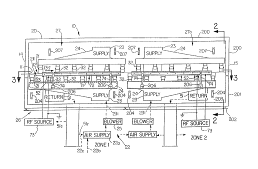
Fig. 1 is a schematic side elevation view of a dryer apparatus for
drying or curing web materials and coatings in accordance with the present
invention;
Fig. 2 is an end view of the dryer of Fig. 1 looking generally in the
direction of the arrows 2--2 from the right end of Fig. 1;
Fig. 3 is a partial top view of the dryer looking generally in the
direction of the arrows 3--3 of Fig. 2;
Figs. 4 and 5 are side elevation section views of exemplary
embodiments of air bar used in the dryer;
Fig. 6 is a schematic isometric illustration of an arrangement of
electrodes and electrode bus frame used in the dryer;
Fig. 7 is a schematic electric circuit diagram of an RF source;
Fiçls. 8 and 9 are schematic illustrations of the travel path of a web
in a dryer in accordance with the invention, the sinusoidal travel path in Fig.
CA 02234084 1998-04-06
W O 97/13110 PCTAUS96/13248
8 being exaggerated for illustrative purpose and an exemplary air bar being
shown in detail in Fig. 9;
Fiç~. 10 is a schematic illustration of the geometric or positional
relationships of electrodes and air bars providing RF through and stray fields
along the web travel path of an exemplary embodiment of dryer;
Fig. 11 is a schematic illustration of the geometric or positional
relationships of shared electrodes and air bars providing an RF stray field
along the web travel path of an alternate exemplary embodiment of dryer;
Fig. 12 is a schematic block diagram of sensors and control circuit
apparatus and functions used in the dryer;
Fig 13 is a mechanical drawing of an exemplary RF detector and
associated circuitry useful in the dryer to provide an input to the control
circuit apparatus of Fig. 12, for example;
Fig. 14 is a schematic electric circuit diagram of the RF detector; and
Fig. 15 is a schematic fragmentary elevation view of a compression
plate mounted between a pair of air bars.
Description
Referring, now, in detail to the drawings, wherein like reference
numerals designate like parts in the several figures, and initially to Figs. 1-3,
a radio frequency (RF) assisted flotation air bar dryer apparatus for drying
and/or curing a traveling web is generally indicated at 10. The dryer 10 is
described below by way of example as being used to dry a water-containing
or wet emulsion coating that is on a paper web 11 which is carried along a
path 12 through the dryer 10 in the direction of an arrow 13 from an
entrance end 14 to an exit end 15 of the dryer. The dryer may be used to
dry or to cure other webs and/or coatings.
Summarizin~ exemplary operation of an embodiment of dryer 10 to
dry a web, RF energy heats the web and/or coating. Air flow from air bars
removes moisture that is emitted from the heated web and/or coating. The
CA 02234084 1998-04-06
W O 97/13110 PCT~US96/13248
16
air flow also may balance tempera~ure of and/or cool the web and/or coating
to avoid blistering or other heat damage.
Conventional drive rolls, idler rolls, supply rolls and take up rolls (not
shown) may be used to supply the web 11 to the dryer 10, to pull the web
through the dryer, and to store the web or otherwise to direct the web for
further processing after exitin~ the dryer. Coating equipment may be used
to apply a coating to the web 11 upstream of the entrance end 14 of the
dryer 10.
Within the dryer housing 20 are a plurality of air bars, nozzles or air
outlets 21 which direct air flow toward the web 11 to support the web
along the path 12 through the dryer 10. In the illustrated embodiments
hereof there are a plurality of air bars 21 on each side of the web 11, e.g.,
above and below the web relative to the illustration of Figs. 1 and 2.
(Directions referred to herein are generally for the purpose of facilitating
description, but it will be appreciated that the various positional and
functional relationships of the components described may be maintained
with respect to each other while in a different orientation or location relativeto the illustrations in the drawings. For example, web travel may be vertical
in which case the air bars may be on opposite sides of the web in relative
left-hand and right-hand relation to the web rather than being above and
below the web, and so forth.)
The air bars 21 are provided with a supply of air from an air supply
system 22, which includes an air source 22a, an air supply duct 23, a
plenum or header 24 and a blower 25. The air source for air supplied to the
blower may be, for example, fresh air 22b, air recirculated 22c from the
dryer or a combination thereof. The blower 25 may provide such air under
suitable pressure and volume to obtain desired air flow from the air bars
with respect to the web 1 1. Air flow is directed from the blower 25 via the
plenum or header 24 (referred to below as "plenum" for brevity) to the air
bars 21. The air bars are constructed and arranged to direct air flow with
CA 02234084 1998-04-06
W O 97/13110 PCT~US96/13248
respect to the web to support the web and to direct the web in a generally
sinusoidal path 12. The amplitude of each "hump" or half wave of the
sinusoidal path followed by the web 11 may be determined by the tension
on the web caused by the con~lentional rolls, drive(s), and/or other
equipment delivering the web into the entrance end 14 of the dryer 10 and
taking up the web out from the exit end 15 of the dryer. That amplitude
also may be determined by the velocity or force and the direction that the
air is directed by the respective air bars 21 against and/or toward respective
surfaces of the web. Such amplitude also may be determined by the density
of the air directed by the air bars with respect to the web; for example,
warm air is less dense than cold air.
in the described embodimentthe fluid medium delivered by the air
bars Z1 is air. However, it will be appreciated that other fluid medium may
be used instead of or in addition to air. One example is an inert gas. Other
liquid, gas, mixture, or other fluid media also may be used. Also, as was
mentioned above, the path 12 preferably is undulating and, for example,
somewhat sinusoidal in shape. However, the path 12 need not be a true
sinusoidal wave shape; it may be other shape, as may be desired.
The dryer 10 also includes an electromagnetic energy system 26
which provides electromagnetic energy to the web. In the embodiment
described in detail here the electromagnetic ener~y is radio frequency (RF)
energy, i. e., electromagnetic ener~y that is in the radio frequency
wavelength or frequency range. However, if desired, electromagnetic
energy that is other than or in addition to RF energy may be used; one
example is microwave energy.
The electromagnetic energy system 26 directs an RF electromagnetic
energy field ~sometimes referred to as a RF field) with respect to the web
11. The RF field causes oscillatory movement of both water molecules and
latex particles in the emulsion coating of the web and, therefore, the heating
of the emulsion coating and the faster diffusion of moisture therefrom.
CA 02234084 1998-04-06
W O 97/13110 PCT~US96/13248
18
Since the RF field usually can penetrate throughoutthe coating (and possibly
the web), a fast moisture diffusion ordinarily will occur throughout the
coating (and web), resulting in a fast moisture removal at the surface.
Reference is made herein to flux of various types, such as heat
transfer flux, mass transfer flux and RF flux. Flux is considered here, for
example, as a rate per unit surface area. For example, heat transfer flux,
which also is referred to herein as drying flux, may be considered a rate of
heat transferring per unit surface area with units of calorie/square meter-
second. As another example, mass transfer flux may be considered a rate
of mass transferring per unit surface area with units of grams/square meter-
second. Similarly, RF flux may be considered as a rate of RF energy
transferring into web material per unit surface area with units of
calorie/square meter-second or KWH/square meter-second (where KWH is
kilowatt hours); alternatively the RF flux may be expressed in KW/square
meter (where KW is kilowatts).
RF flux also may be considered the rate of RF energy transferring into
web material per unit surface area with units of KW/square meter, where the
RF energy includes both the RF energy used for dielectric heating the web
materials and the energy loss due to converting of the RF power from the
DC power circuit from which the RF energy is developed.
In an exemplary embodiment of the present invention the RF flux has
a loss portion of about 40% and an RF heat generation portion of about
60% from a total DC power supply.
In an exemplary embodiment of dryer apparatus 10 and method in
accordance with the invention a 27 inch wide web is moved through a two
zone dryer, each zone being about 10 feet in length, at a line speed of about
222 fpm (feet per minute). The web surface area in each zone is about
2.09 square meters (22.5 square feet). In the first (upstream relative to
web travel direction) and second (downstream) zones the air temperature is
about 140~F and 190~F, respectively; the nozzle air velocity from the air
CA 02234084 1998-04-06
W O 97/13110 PCTAJS96/13248
19
bars is about 8,000 fpm; the RF DC voltage is about 10KV and 6.9KV,
respectively; and the DC plate current is about 5 amps and 0.8 amps,
respectively. From the above information the RF flux in the first zone is
calculated as 1 OKV x 5 amps/2.09 square meters = 23.9 KWlsquare meter;
and in the second zone is calculated as 6.9KV x 0.8 amp/2.09 square
meters = 2.64 KW/square meter.
In another exemplary embodiment of dryer apparatus 10 and method
in accordance with the invention a 78 inch wide web is moved through a six
zone dryer, each zone being about 20 feet in length, at a line speed of about
1,250 fpm. The first four zones include air bars but no RF energy source,
application electrodes or the like; the fifth and sixth zones include RF energy
source and electrodes to apply RF energy to the web in those zones as
disclosed herein, for example. The web surface area in each zone is about
12.08 square meters (130 square feet). In the respective fifth and sixth
zones the air temperature is about 140~F and 147~F, respectively; the
nozzle air velocity from the air bars is about 8,300 fpm and 8,500 fpm,
respectively; the RF DC voltage is about 13KV and 11 KV, respectively; and
the DC plate current is about 18.5 amps and 15 amps, respectively. From
the above information the RF flux in the fifth zone is calculated as 13KV x
18.5 amps/12.08 square meters = 19.9 KW/square meter; and in the sixth
zone is calculated as 11 KV x 15 amp/12.08 square meters = 13.7
KW/square meter.
In still another exemplary embodiment in which RF energy is applied
to the web as in the preceding example for all six zones of the dryer 10,
each zone being about 20 feet in length, the line speed for the web is about
1,500 fpm, and the RF flux for the fifth and sixth zones are about 5% to
about 10% greater than the RF flux level of 20 KW/square meter; the other
four zones are at about 50% lower RF flux than the RF flux at the fifth or
sixth zone.
CA 02234084 1998-04-06
WO 97/13110 PCT~US96/13248
In another embodiment the RF flux in a particular drying zone is about
40 KW/square meter. Also, in another embodiment, it the RF flux may be
less than 20 KW/square meter. The actual drying flux used may depend on
characteristics of the web product and/or coatin~ material bein~ dried in the
dryer.
In an embodiment of dryer 10 and method according to the invention
the RF flux in one or more drying zones is from about 1 to about 50 KW/m2.
In an embodiment of dryer 10 and method according to the invention
the RF flux in one or more drying zones is from about 2 to about 40 KW/m2.
In an embodiment of dryer 10 and method according to the invention
the RF flux in one or more drying zones is from about 2 to about 24 KW/m2.
In an embodiment of dryer 10 and method according to the invention
the RF flux in one or more drying zones is from about 2 to about 20 KW/m2.
A non-limiting example of a wet emulsion coating on a paper web is
a coatinç~ that is about 50 microns thick having individual polymer particles
that are of a size on the order of from about 0.01 micron to about 30
microns diameter. The RF field tends to penetrate and heat the coating
substantially throughout the thickness thereof to cause moisture to diffuse
out to the coating surface. Thë invention may be used to dry coatings
having lar~3er or smaller individual particle diameter.
The same effect of RF energy can be achieved for most of particulate
systems such as (A) Micro-emulsion coating having the particle size range
between 0.01-0.05 micron in diameter; (B) Emulsion coating having typical
particle size range between 0.08 - 0.8 micron in diameter; (C) Micro-
suspension coating having the particle size range between 10 - 30 micron
in diameter. RF energy can penetrate and heat these coatings very fast and
thus cause moisture to diffuse out fast to the surface and subsequentiy the
moisture on the surface can be mass-transferred out through turbulent air
provided by air bars. A non-limiting exemplary emulsion with which the
CA 02234084 1998-04-06
W O 97/13110 PCTrUS96/13248
invention may be used according to an embodiment has a particle size range
between 0.1-0.4 micron in diameter.
The air flow provided by the air bars 21 may have one or several
functions. For example, the air flow may provide a cooling effect to cool the
web and especially the coating to prevent blistering while the RF field is
heating the coating and/or web to cause water to be emiKed therefrom.
Providing such cooling effect helps to assure that a skin does not form
prematurely on the surface of the coating and block water emission from the
coating. Another advantage to using air flow for cooling rather than heating
the web is that energy does not have to be expended to heat the air, and
efficiency is not lost by requiring air to heat the web. Rather, heating can
be carried out solely, partly, or primarily by the RF field, which may couple
energy to the web more efficiently than does an air flow.
If desired, the air flow may be used to heat the web 11 to assist in
the heating function that also is carried out by the RF field. Also, the air
may be heated while still providing a cooling or temperature balancing or
maintaining function, as the RF energy provides heating; the air temperature
may be less than the air temperature required in the past when the air was
used as the primary source of heating.
The air flow also is used to carry moisture emitted from the coating
of the web away from the web for disposal elsewhere.
The dryer apparatus 10 may be arranged in a single zone whereby the
drying zone 27 is formed by a single group of air bars and one or more
plenums 24, such as that depicted in the left hand portion of Fig. 1. If
desired, though, the dryer 10 may include several zones, each of which
effects drying in the same way or in different ways. For example, the drying
zone 27 at the left hand side of Fig. 1 may provide drying function wherein
the RF energy is at a particular level and desired heating or cooling is
provided by the air flow from the air bars; and the RF energy and/or air
CA 02234084 l99X-04-06
W O97/13110 PCTAUS96/13248
temperature may be different at the drying zone 27a shown at the right-
hand side of Fig. 1.
Referring to Fig. 4, one example of an air bar 21 is shown
schematically in cross section. The air bar 21 includes a generally
rectangular shape housing 30 which has an interior chamber or volume 31
into which air is directed under pressure from the plenum 24. The air bar
housing 30 may be mounted on a support duct 32, which is attached to the
plenum 24, and the housing 30 may be slid along the support duct 32
toward or away from the web path 12 to a desired location with respect
thereto .
A wall 33 of the air bar housing 30 has an inlet opening 34 through
which the support duct 32 enters the housing chamber 31 to direct air from
the plenum into the chamber. A seal assembly 35, such as an o-ring,
packing or the like 36, cooperates with the housing 30, a seal retaining wall
37, and wall 33 to block air leaka~e from the chamber 31 out past the
outside of the support duct 32. The seal assembly 35 provides a frictional
fitting engagement with the support duct 32 so that absent an intentional
adjusting of the position of the housing 30 on the support duct 32, such
housing will remain in a relatively fixed position on the support duct. A
screw or other fastener (not shown) also may be used to secure the air bar
21 in position on the support duct 32.
The outlet end 40 of the air bar housing 30 includes an outlet opening
41 in a wall or face 42 of the air bar 21 opposite the wall 33. The outlet
opening 40 is partly blocked by a fluid directing outlet ca~ or deflector 43.
The housing 30 may be formed of sheet metal folded to the
configuration shown in Fi~.4. In Fig.4 the air bar is shown in a section end
view; the width of the air bar into the paper of the drawing of Fig. 4 and
into the paper of the drawing of Fi~.1 may be about the same as or longer
than the maximum width of the web 11 so that air will be directed with
O respect to and across the entire width of the web as it passes the air bar.
CA 02234084 1998-04-06
W O 97/13110 PCT~US96/13248
Air bar length may be considered in the direction of web travel. The actual
direction of air flow and where it flows with respect to the web 11 may be
from perpendicular to, at an acute angle to, substantially parallel or
otherwise relative to the web- A change in the configuration of the outlet
end 40, cap 43, etc. can be used, for example, to change the air flow
direction(s). The outlet cap 43 may be folded sheet metal material in the
shape shown in Fig. 4 or it may be otherwise formed. The outlet cap 43 is
attached at corners 44, for example by welding, screw and nut connection,
or friction fit, to walls 45 of the air bar housing 30.
O The outlet cap 43 has an air distribution chamber 46 and one or more
outlet passages 47. In the illustrated embodiment of Fig. 4 two of the air
outlet passages 47 are in angled side walls 48 of the outlet cap 43, and one
air outlet passage 47a is in the top wall 49 of the cap 43.
As is seen in Fig. 4, the cap wall 48 and the face wall 42 cooperate
to form slot-like ~aps 50 through which air flow exits the air bar 21 along
the width thereof for impingement on the web 11. Since the air is not used
primarily for heating of the web, but rather primarily is used to remove
moisture emitted from the web, and/or to balance web temperature or to
cool the web, as heating is carried out primarily by the RF energy, the size
0 of the gaps 50, the spacing of the gaps in an air bar and, thus, the length
of the air bar and size of the face 42, the spacing of the air bars from each
other and/or the air flow velocity may be larger than in prior air floatation
dryers.
In operation of the air bar 21, the housing 30 is adjusted to an
appropriate location on the support duct 32 to place the outlet opening 41
of the air bar and cap 23 in a desired location relative to the web 11. Air
from the supply 23 (Fig.1) is delivered via the plenum 24 and support duct
32 into the air bar chamber 31. The air in the chamber 31 is under pressure
so that it is forced into the air distribution chamber 46 of the outlet cap 43
,0 and out through air outlet passages 47 to flow with respect to the web 11.
CA 02234084 1998-04-06
W O 97/13110 PCT~US96/13248
24
In the illustrated embodiment air exiting the outlet passage 47a flows
directly toward the web. Air exiting the outlet passage 47 is deflected by
the an~led face walls 42 to flow out throu~h 9aps 50 between the
respective walls 42 and 48. The cooperative relation between various walls
of the air bar 21 where the air flow exits can determine the direction of air
flow, the extent that the air flow is turbulent or laminar, and to an extent
the volume of the air flow. In the illustrated embodiment the air flow exiting
the air bar 21 is directed with respect to the web in a direction toward the
web, and that air flow is somewhat turbulent in order to achieve a wiping
0 action with respect to the web for good thermal energy transfer between
the air and the web. Such air flow also picks up the moisture emitted from
the web to remove it from the presence of the web, especially as the air is
withdrawn from the dryer housing 20 through an outlet 51 (Fig. 1).
The air bars 21 and air flow provided by the invention maintain a
relatively high mass transfer rate to remove moisture from the area of the
web. Also, since the primary heating is provided by RF energy, the air flow
may not need to be used to provide heat transfer to the web; although, if
desired, the air flow may provide such heat transfer and also may be used
to provide cooling or balancing of temperature, e.g., to avoid blistering or
'0 other heat damage to the web. Thus, the invention provides drying of the
coating while the coating is maintained substantially free of defects due to
or caused by or in the drying process. In contrast, prior air floatation
systems which used air bars relied on air flux to provide both heat transfer
and mass transfer. In such prior systems the air bars were spaced relatively
close together and the length of each, i.e, space between air outlet gaps,
and gap size were relatively smaller than is possible in the present invention
to maximize heat transfer and mass transfer. In the present invention lar~er
faces 42, gaps 50, distance between gaps 50 permits a greater air flow per
air bar than was possible in the past since the air flux may be used primarily
for mass transfer and secondarily for heat transfer. Also, since there is a
CA 02234084 l998-04-06
W O 97/13110 PCT~US96/13248
greater air flux per air bar 21 of the invention than in air bars used in prior
air floatation dryers, there may be lar~er distance between air bars while stillproviding approximately the same air flux for mass transfer. The larger
spacing between air bars reduces the complexity of the dryer, reduces the
number of undulations of the web in its path 12 through the dryer, and
permits greater flexibility in controlling the direction of the path, e.g.,
amplitude of the respective undulations than was possible in the past.
Several examples of air bar size and spacing are presented elsewhere
herein. These are not intended to be limiting but rather are intended to
0 demonstrate operation of the invention consistent with the description
hereof .
An example of an alternative form of air bar 21' is shown in Fig. 5.
The air bar 21'is similar in function to the air bars 21 described elsewhere
herein and similar parts are designated by the same reference numerals,
except in Fig. 5 the reference numerals are primed. The air bar 21' has a
relativeiy longer height dimension from the base wall 33' to the face wall
42'. At the base 33'iS an opening 34' into which a riser support duct 32
of the plenum 24 extends to deliver air to the air bar. The air flows through
the air bar 21' (vertically upward relative to the illustration of Fig. 5). The
0 air flow is discharged out through gaps 50' in the face 42'. The gap 50' is
on the order of about 0.159 inch, and such dimension provides a similar air
flow result as that described above with respect to the air bars 21 in order
to increase to more than twice the amount of air flow compared to the air
flow of air bar configurations and uses in prior air floatation dryers. Several
!5 ribs 53 within the housing 30' of respective air bars 21' provide
strengthening and rigidity for the air bar. Space between ribs allows
substantially unimpeded air flow through the air bar. Also, the ribs 53 may
provide a stop to limit the distance that a support duct 32 from the plenum
24 can protrude into the air bar.
CA 02234084 1998-04-06
W O 97/13110 PCT~US96/13248
26
The air bars 21 are used as electrodes in the electromagnetic ener~y
system 26 of the dryer apparatus 10. Therefore, the air bars have
electrically conductive characteristics. For example, the air bars 21 may be
formed of aluminum, stainless steel or other electrically conductive material.
Preferably the air bars are not formed of ferromagnetic material to avoid
becoming magnetized. To avoid arcing, the front and back edges 42L, 42R
e.g., the edges at the left and ri~hts sides of the air bar illustrated in Fil3. 4
near the outlet opening 41 and, if necessary, other edges should be rounded
as much as possible, and the surface of each rounded edge should be as
O smooth as is reasonably possible. Also, any points of attachment by
welding, fasteners (nuts, bolts, screws, etc.), or other means of attachment
o~ each air bar, such as where the outlet cap 43 is attached to the housing
30, electrical connections 52, etc. should be deburred and smoothed to
avoid sharp points, edges or surfaces where arcing might occur.
As is seen in Figs. 1-7, the electromagnetic energy system 26
includes a plurality of electrodes 71 which are mounted in a frame 72 and
are coupled to an RF power generator circuit 73. The RF generator circuit
73 may be shared by plural zones 27, 27a, etc., or a separate circuit 73
may be used for respective zones. The electrodes 71 may be metal tubes,
O such as aluminum or stainless steel tubes, rods, wires, or other electrodes.
The frame 72 may be made of electrically conductive material, for example
aluminum or other material, and it may serve as an electrical bus to supply
electrical energy, such as an RF wave or signal, to the electrodes 71.
As is shown in Fig. 7, the electrode bus frame 72 includes a pair of
C-shape channels or elongate members 72a, 72b. These members may be
made of aluminum plate bent with such C-shape or they may be of other
suitable material to provide support for the electrodes 71 and preferably also
to conduct electrical energy to the electrodes. The members 72a, 72b may
be extruded or otherwise formed. The electrodes 71 are fastened at
~0 opposite ends to respective members 72a, 72b of the electrode bus frame
CA 02234084 l998-04-06
W O 97/13110 PCTAJS96/13248
7Z by an electrically conductive bolt 72c, for example of brass. The
electrode bus frame 72 preferably is electrically conductive to supply RF
wave (electrical/electromagnetic) energy to each electrode 71 . Other means
may be used to provide energy to the electrodes to produce a RF field
output. The electrode bus frame 72 usually does not require electrical
insulation since the RF wave can transmit and propagate out through
insulating material (e.g., rubber) to a neighboring ground.
The frame 72 is supported in the dryer housing 20 by several
insulating supports 74 (Figs.1-3), such as steatite insulator rod supports or
l O other support structure. Preferably the supports 74 permit the adjusting of
the position of the frame 72 and, thus, electrodes 71 in the dryer housing
20 to place the electrodes 71 at desired locations relative to the web path
12 and the air bars 21.
In operation of the electromagnetic energy system 26, the RF power
generating circuit 73 supplies electrical energy to the electrodes 71 at such
power and frequency to cause the radiating of an RF field with respect to
one or several air bars 21, 21', which are grounded relative to the circuit 73.
If desired, one or more air bars may be "hot" or ungrounded and one or
more of the frame electrodes 71 may be grounded and appropriately
ZO electrically insulated from the electrode bus frame 72 and/or the other
electrodes 71. However, it is preferred that the air bars are grounded to
minimize other electrical insulation requirements of the dryer 10.
When an electrode 71 on one side of the web 11 directs an RF field
to an air bar on the same side of the web, that RF field is referred to as a
stray field. When the electrode 71 directs an RF field to an air bar on the
opposite side of the web 11, the RF field is referred to as a through field.
Usually a stray field tends to graze the web and does not deliver quite as
much direct or concentrated energy to the coating as does a through field.
Blistering of the coating may occur, for example, when the RF energy
delivered to the coating is so great as to cause an excessive temperature of
CA 02234084 1998-04-06
WO 97/13110 PCTrUS96/13248
28
the coating. An RF stray field does not usually provide the most intense
part of the field to the coating. Therefore, the likelihood of excessive
heating of the coating and blistering is reduced when an RF stray field is
used. Also, an RF stray field may be directed through a larger extent of the
coating than an RF through field, and, therefore, such stray field may
provide a more uniform heating effect over that extent.
The present invention also avoids the aforementioned blistering even
though substantial electromagnetic ener~y can be delivered to the coating
by stray field and/or through field because of the cooling air flow provided
O by the air bars 21 to avoid excessive temperature conditions that would
cause blistering.
In Fig. 7 is a schematic circuit diagram of the RF source 73. The RF
source 73 includes a DC power supply 75, and an oscillator 76. An
exemplary DC power supply may include an AC input 75a, e.g., from a 460
volt, 3 phase, 60 Hz power source, which is transformer 75b coupled to a
full wave rectifier 75c in turn coupled to a DC power output circuit 75d,
which includes one or more capacitors, indicators and/or resistors, as well
as other components, if necessary, to provide desired filtering, voltage
multipiication, etc., as is known in the art of DC power supplies. Ground is
~O designated 75e.
The oscillator 76 shown in Fig. 6 includes a ç~enerator triode 77, a
tank circuit 78, and associated circuitry. In one example, the generator
triode 77 is model RS 3150 CJ sold by Siemens. Such ~enerator triode is
a metal-ceramic triode that is water cooled, and it is able to produce an
Z5 output at frequencies up to about 100 MHz with oscillator power up to
about 240 KW. Other generator devices also may be used as equivalent
substitutes for the ~enerator triode 77 to provide a suitable drive for the
oscillator 76 to obtain the desired RF output from the RF source 73 for the
purposes described herein.
CA 02234084 l998-04-06
W O 97/13110 PCT~US96/13248
29
The cathode of the generator triode 77 is coupled to ground. In the
grid circuit of the generator triode 77 are a grid coil 76a; adjustable
capacitor 76b, which is adjusted over its range of capacitance, for example,
from about 25pf to about 450pf, by a motor 76c; grid choke 76d; capacitor
76e; and grid resistors 76f. A ~rid current meter 769 can measure and
display (or feed back for control) information representing grid current. By
adjusting the capacitor 76b operation of the generator triode 77 can be
adjusted/controlled. The size range of adjustment for the capacitor 76b is
exemplary; the range may be larger, smaller and/or may extend beyond one
O and/or the other exemplary boundary. Also devices other than a motor 76cmay be used to adjust the capacitor, such as, for example, manual control,
electronic control, etc.
The plate electrode of the generator triode 77 is coupled via a plate
choke 76h to receive DC power from the DC power supply 75, and it is
coupled via a plate blocking capacitor 76i to the tank circuit 78.
As is seen in Fig. 7, the tank circuit 78 includes the air bars 21 and
the electrodes 71 which are coupled across a tuning stub 78a. Connections
are made at 52 and 72 to respective air bars 21 and the frame 72. The
desired RF field between the respective electrodes 71 and air bars 21 is
~O developed by the oscillator 76 when energized by the DC power supply 75.The RF field is applied to a load 79 between respective electrodes and air
bars. The load may be, for example, the web and/or air or other material in
the path of or otherwise appropriately located relative to the RF field.
In the RF source 73 may be various meters, for example, meters 77a,
~5 77b to measure plate voltage and plate current. The measured values frommeters 76g, 77a, 77b may be used for monitoring and/or control of the RF
source 73.
The above description of the RF source 73 is exemplary, and it will be
appreciated that other sources of RF field and/or RF energy may be used to
provide the desired operation of the invention to dry webs. Also, although
CA 02234084 1998-04-06
W O97/13110 PCTAJS96/13248
one example of a DC power supply 75 and oscillator is shown in Fig. 7, it
will be appreciated that other DC power supplies and/or oscillators may be
used to provide suitable electrical energization of and output from the
oscillator 76 to obtain the desired RF stray and/or through fields for the
purposes described herein.
Turning to Figs. 8 and 9, schematic illustrations show exemplary
travel paths 12 of the web 11. Shown in Fig. 8 in exaggerated form is an
exemplary sinusoidal travel path 12 of the web 1 1 relative to an exemplary
RF stray field 80 and RF through field 81. The web 11 passes over a feed
0 roll 82 and enters the dryer housing 20 at entrance 83. The entrance 83
includes a seal 84, which may provide thermal seal function and RF seal
function preventing the transmitting of thermal energy between the exterior
and interior of the housing 20 and preventing leakage of the RF
electromagnetic energy from within the housing to the external environment.
Exemplary thermal seals may be those used in conventional air flotation
oven dryers, and exemplary RF seals may be those used in conventional RF
ovens or other devices, microwave ovens or the like
In the housing 20 a first air bar 21 a directs an air flow 85 toward the
web 11 causing a first curved or somewhat sinusoidal hump 86 in the web
0 in an up direction relative to the illustration of Fi~. 8. A second air bar 21 b
just downstream along the web path 12 of the air bar 21 a directs an air flow
87 down toward the web 11 causing a second hump 88 in a direction down
relative to the illustration. The air flow from air bars 21a, 21b not only
provides support and alignment of the web 11 as it travels along its path 12
through the dryer 10, but also the air flows 85, 87 create a curved,
sinusoidal or the like character of the path 12 and web traveling along that
path. Considering the path as somewhat of a sinusoidal one, the
wavelength depends on the relative spacing of the air bars, and the
amplitude of the respective humps 86, 88, for example, depends on the air
0 flows 85, 87, the force and volume with which the flows impinge on the
CA 02234084 1998-04-06
W O 97/13110 PCT~US96/13248
web, web tension provided by various rolls, such as roll 82, feed and take
up drives, and possibly other air flows and conditions in the housing 20. As
the amplitudes of the half wave humps 86, 88, for example, change, the
angle or slope of the web from the horizontal relative to the illustration of
Fig. 8 may change. An exemplary angle A in Fig. 8 represents the
steepness of the slope of the web 11 approximately in the area where the
RF field may impinge on the web.
The angle at which the stray field 80 impinges on the web and the
amount of penetration of the stray field into the web can be controlled by
controlling the amplitude of the respective half wave humps 86, 88 and by
controlling the magnitude and dispersion of the RF stray field 80. Dispersion
here refers to whether the RF stray field travels directly, e.g., in a straight
line, from the electrode 71 to the air bar electrode Z1 a or whether the stray
field is distributed over a wider area, such as that represented by the several
dashed line arrows in Fig. 8. Some characteristics of the RF field, such as
dispersion, magnitude, or intensity, frequency, direction, etc. can be
controlled by adjustments in the RF source 73 and location, shape and
arrangement of electrodes and air bars, for example. In the illustrated
embodiment, if the stray field has relatively small dispersion and the angle
A is relatively large, then a relatively small amount of stray field will impinge
on the web; in contrast, a relatively small angle A and a relatively large
amount of dispersion will result in a relatively larger amount of stray field
impinging on the web. Similarly, the extent that the RF through field 81 is
distributed in the web 11 as the web passes through that through field can
be controlled by controlling the angle A and the dispersion occurring in the
RF through field. Other equivalent mechanical, angular, and directional
relationships also may be employed to obtain a control of the impingement
relationship between the RF field and the web. Therefore, by controlling and
coordinating the air flows 85, 87 with the magnitude and dispersion of the
respective RF stray field 80 and through field 81, the heating, water
CA 02234084 1998-04-06
WO 97/13110 PCT~US96/13248
releasing, etc. function of the RF fields with respect to the web can be
controlled .
In the present invention the air bars may be of a size relatively larger
than those used in prior air flotation oven dryers. For example, the
approximate length of the air bar in the direction of web travel in prior air
floatation dryers was on the order of about 2 inches and in the present
invention that length has been enlarged to between about 3.4 to about 6
inches. Also, the air outlet openings, such as the gaps 50, 50' are larger
than those used in the past preferably to increase, e.g, to double, the
volume of air flow for cooling, heating and removing of moisture emitted
from the coating of the web compared to prior air bars.
An example of size, configuration and operation of the air bars 21,
21' is, as follows. The air bars 21 on one side of the web 11 are arranged
at a spacing of about 20 inches apart; and a similar spacing is provided
between air bars on the opposite side of the web. The air bars on one side
of the web are about equally spaced between the air bars on the other side
along the web path. This spacing size has been found adequate to provide
space to locate two electrodes 71 between the air bars on one side of the
web. Other spacing also may be used, as may be desired.
0 Each air bar has two slot-like gaps 50, respectively near the relatively
upstream and relatively downstream edges of the air bar (i.e., relative to
direction of web travel). The size of the open gap 50 is on the order of
about 0.155 inch. The dimension between gaps 50 is on the order of from
about 3.4 inches to about 3.8 inches. These air bars 21 can deliver air flux
of about 82 ACFM/sq. ft. at the 20 inch air bar spacing. The air bars 21
deliver air flux at more than twice the air flux of air bars of prior air
floatation dryers. Also, the high air flux provided by the present invention
air bars is able to carry away moisture from the area of the web at more
than twice the rate at which moisture from the area of the web at more than
CA 02234084 1998-04-06
W O 97/13110 PCT~US96/13248
twice the rate at which moisture is emitted; and this further enhances the
emitting of moisture from the web.
The dimension of the face 42 of the air bars 21 in the direction of
web travel is larger than that dimension for prior air bars, and the width of
the gaps 50 in that direction also is about twice as ~reat as that in prior air
bars. These characteristics allow for a greater air flux capability than prior
air bars. Since according to an embodiment of the invention a primary
function of the air flow is to carry away moisture from the area of the web
11 while the RF field provides heating of/for the web, the larger air flux of
O the invention can be utilized without significantly increasing energy usage
to heat more air. Also, since the air may primarily carry away moisture
rather than to heat the web, the air impingement area on the web need not
be so concentrated or narrow as was required for prior air bars and systems
using them; accordingly, compared to prior air bars and systems the
relatively large size of the air bar face 42, spacing between gaps 50 of an
air bar 21, air flow and air flux provided by the air bars of the invention
provide improved operation and efficiency.
Preferably each electrode 71 has enough space in its positioning in
the area between air bars to prevent unnecessary arcing to the neighboring
air bars 21, plenums, etc., which are grounded. Each air bar 21 has a
relatively long height dimension between the air bar face 42 and the opening
34 in the wall 33 of the air bar receiving the support duct 32 from the
plenum 24. For example, the distance from the header (plenum) support
duct opening 34 to the air bar face 42 may be on the order of from about
5 inches to about 10 inches. The distance between respective electrodes
71 and neighboring air bars 21 on the same or opposite side of the web 11
preferably is adequate so that there is no arcing but there is the desired
transmitting of an RF field.
The additional space between air bars compared to the usual spacing
of air bars in prior air floatation dryers provides room for increasing the
CA 02234084 1998-04-06
W O 97/13110 PCTAUS96/13248
34
height of the half wave humps 86, 88 in the sinusoidal travel of the web 11
as the air flow thereto is increased; this further increases the control
capabilities of the invention, e.g., facilitatin~ control of the manner and
extent that the RF stray and/or through field(s) impinge on the web.
Referring to Fig. 9, an enlarged drawing example of the web 11
curvature (sinusoidal or undulating path 12, for example) in relation to an
electrode 71 and two air bars 21a, 21b is shown. A line 12b is a straight
non-undulating path extending along the length of the dryer housing 20, and
the air bars 21 a, 21 b and electrode 71 as shown are on respective sides of
and do not intersect that line. Therefore, in case the web is moved through
the dryer housing when air is not flowing from the air bars, the web
ordinarily would not touch the air bars or electrodes. In the illustration of
Fig. 9, the web 11 may be maintained spaced about equidistant above or
below respective portions of the air bars 21a, 21b, as is represented, for
example, by arrow C (this providing for substantially uniform effect of the
air flow thereon); an exemplary distance is from about 114 inch to about 3/4
inch and more preferably from about 3/8 inch to about 5/8 inch.
Dimensions D, Da from the electrode 71 to respective air bars 21, 21 a also
may be the same (or different) depending on the desired characteristics of
RF stray and/or through fields. Geometrical path lengths for consideration
of the RF stray and through fields are represented by lines 80a, 80b,
respectively. The characteristics of such fields may depend on such
geometrical considerations, size of parts, e.g., diameter of the electrodes
71, output from the RF source 73, load impedance, etc.
Referring to Fig. 10, an exemplary schematic arrangement of
electrodes 71, air bars 21 and web 11 in a dryer apparatus housing in
accordance with the invention is illustrated. Plural air bars 21a are located
beneath the path 12 of the web 11, and a plurality of air bars 21b are
located above the path of the web. Electrodes 71 all are located beneath
the path of the web 11 and are connected to the RF power ~enerator 73.
CA 02234084 1998-04-06
W O 97/13110 PCT~US96/13248
- 35
The web path 1 2 is somewhat sinusoidal in shape in response to the air flow
from the respective air bars. The air bars are supplied with air via the
plenum 24. Each of the air bars 21 is coupled to an electrical ground 99.
Safety is enhanced because the grounding of the air bars and associated
structure to which they are attached or supported avoids the possibility of
an operator being electrically shocked and also helps to avoid the possibility
of inadvertent leakage of the RF field and of having unintended RF fields in
the dryer housing.
In operation of a dryer 10 configured in the manner depicted in Fig.
0 1 0, the electrodes 71 direct RF stray fields 80 and RF through fields 81 with
respect to the web 11, and the air bars direct air flows with respect to the
web 11. A single electrode 71 may provide only an RF through field, only
an RF stray field or both an RF through field and an RF stray field, as is
shown with respect to the various electrodes illustrated in Fig. 10. It also
is evident from Fig. 10 that a single air bar may be used as the ground
electrode for one or more electrodes 71 and the RF stray field or through
field may be provided by such electrode(s) 71. An electrode 71 may provide
only a through field, such as the electrode 71a shown at the left-hand side
of Fig. 10; an electrode may provide only a stray field, as is shown at 71b
0 at the right-hand side of Fig. 10. Also, an electrode may provide both
through field and stray field, if desired, as is represented by the five
electrodes 71 intermediate of the two end electrodes 71a, 71b in Fig. 10.
Fig.11 is another example of an arrangement of electrodes 71 and air
bars 21a, 21b with respect to a web 11 for a dryer 10 according to the
invention. In the embodiment illustrated in Fig. 11 a single electrode 71c is
shared with and provides with respect to two air bars 21a respective RF
stray fields. No RF through field is provided to the air bars 21b. In this
embodiment, if desired, the air bars 21 b may be electrically non-conductive
to avoid a through field being directed with respect thereto.
CA 02234084 1998-04-06
W O 97/13110 PCT~US96/13248
36
It will be appreciated that other arrangements of electrodes and air
bars may be used to develop and to apply with respect to a web RF stray
fields and/or RF through fields. For example, although electrodes 71 are
illustrated being positioned only on one side of the web, they also or
alternatively may be at the other side of the web. Also, if desired, additional
grounded or "hot" electrodes may be used to develop the respective RF
fields without relyinç~ on or in addition to relying on the air bars to provide
grounding or "hot" electrode function.
Referring to Fig. 12, a monitor and control system 100 to provide a
0 number of monitoring and control functions for the dryer 10 is shown. Theweb 1 1 travels through a drying zone 27 in the housing 20 of the dryer 10.
The system 100 may monitor and control several zones 27, 27a or a system
100 may be used for respective zones 27, 27a, etc. In the drying zone 27
the air bars 21 direct air flow with respect to the web and the electrodes 71
develop RF stray field and/or RF through field for application with respect to
the web. The RF field(s) tend(s) to heat the web and especially the water-
containing emulsion coating of the web causing water to be emitted from
the coating and the coating, therefore, to be dried. The air flow from the air
bars 21 may tend to cool the web or at least to maintain a temperature that
0 avoids blistering conditions and to carry away the emitted moisture. Air
flow from the air bars 21 may heat the web, if desired.
The monitor and control system 100 includes an RF detector and
control system 102 which detects the magnitude of the RF ener~y in the
drying zone 27. The system 102 includes an RF detector 103, which is
described below with respect to Figs. 13 and 14, and a programmable logic
controller (hereinafter referred to as "PLC") 104 which receives an input
from the detector 103 and may control the RF power ~enerator circuit 73
and/or the electrical signal delivered to the electrode(s) 71. Such control
may be provided by controlling the magnitude of the volta~e supplied to the
0 RF power generator circuit 73 from a voltage source, electrical power source
CA 02234084 1998-04-06
W O 97/13110 PCT~US96/13248
or connection there to shown at 105 via a control line 106. The control
~ may be of the power, amplitude, frequency, etc. of the electrical energy
and/or circuitry and, thus, of the RF field provided to the web 11. The PLC
104 may be programmed to maintain a substantially constant amplitude of
RF field in the drying zone 27 as detected by the detector 103. The PLC
104 may be a PID (proportional, integral, differential) type controller which
provides the specified control functions in conventional way. If desired, the
RF field may be detected at several locations in the drying zone 27 or at
specified locations relative to the zone, and the respective magnitudes
0 detected may be used to control the field at those respective locations, for
example, by different respective electrodes 71, which may be coupled to
respective attenuating circuits and the RF power generator circuit 73.
The PLC 104 also may include alarm indicators or similar devices 107,
108, which are activated to provide an output or control function in the
event the PLC 104 receives a signal from the sensor 103 indicating that the
sensed RF field is at an alarm limit that is either too low or too high. The
alarm devices 107, 108 may be signal lights or they may be separate
transducers and/or controls that may shut down the coating system on
account of improper drying occurring in the dryer 10. A transmitter 109
0 may be used to transmit information from the detector 103 to the PLC 104.
A web temperature detector and control system 112 monitors the
temperature of the web 11 and delivers that temperature information as an
input to the RF detector and control system 102 and to an air temperature
detector and control system 122 described further below. The web
temperature detector and control system 112 includes a detector or sensor
113, such as a pyrometer device, infrared sensor (e.g., Gentri Model No.
ATC-600), thermistor, thermocouple, etc., which is able to detect the
temperature of the web 1 1 and/or the environment immediately adjacent the
web, which may acceptably represent the temperature of the web itself.
~0 The temperature detector 113 preferably is located at the outlet of the
CA 02234084 l998-04-06
W O 97/13110 PCT~US96/13248
38
drying zone 27. However, the detector 113 may be located in the drying
zone and, if desired, there may be a plurality of detectors for detecting web
temperature at more than one location in, beyond, and possibly upstream of
the dryin~ zone 27. An electrical signal representing the web temperature
as sensed by the detector 1 13 is delivered to a PLC 1 14, which may be and
operate similar to the PLC 104. The PLC 114 is coupled to alarm limit
devices 117, 118, which may be similar to the devices 107, 108, to
indicate that a low or high temperature condition exists and/or to effect
control in response to the occurrence of such a condition, e.g., by shutting
down the web coating line and/or the dryer 10. A transmitter 1 19 may be
used to transmit information from the detector or sensor 113 to the PLC
1 1 4.
A signal representing web temperature is directed by the PLC 114 as
an input both to the PLC 104 of the RF detector and control system 102
and to the air temperature detector and control system 122. The PLC 104
may respond to the signal from the PLC 114 to provide a control signal on
line 106 to increase or to decrease the magnitude of the RF field, for
example, thereby to bring the web temperature into the desired range
expected at the sensor 113 for proper drying function.
The air flow from supply line or duct 23 into the respective plenums
24 to the air bars 21 is shown in Fig. 12. Also shown in Fiç~. 12 is the air
removal or exhaust line or duct 51. Air is supplied to the plenums 24 above
and below the web 11 relative to the illustration in Fig. 12, and air is
exhausted from zones above and below the web and is conducted via the
exhaust duct 51 for exhausting to the external environment via a flow path
51e or for recirculation (a possible energy saving feature) via flow line or
duct 51r (also designated 22c in Fig. 1). Fresh air (sometimes referred to
as make-up air) is provided from line or duct 23b for delivery to the supply
duct 23 possibly in combination with recirculated air from duct 51r.
CA 02234084 1998-04-06
W O 97/13110 PCTAJS96/13248
39
The air temperature detector and control system 122 includes a
temperature detector or sensor 123 in one or both plenums 24 of zone 27,
for example. The sensors 123 may be located elsewhere, if desired. The
purpose of the sensors 123 is to sense or to detect the temperature of the
alr flow which is directed with respect to the web 11 by the air bars 21. A
signal representing such temperature information is delivered to an air
temperature PLC 124, which may be and operate similar to the PLC 104.
Associated with the PLC 124 are low and high alarm limit devices 127,128,
which may be similar to the alarm limit indicators 107, 108 and 117, and
118 described above respectively, to provide a visual or audible indication
that air temperature conditions are below or above a prescribed alarm limit.
The alarm limit devices also or alternatively may provide signals to stop the
coating and/or drying process of the coating line and/or dryer 10 in the
event a limit condition occurs. A transmitter 129 may be used to transmit
information from the detector or sensor 1Z3 to the PLC 124.
The air temperature PLC 124 provides a signal to a device 130, which
can chill and/or heat the air in line or duct 131. The device 130 may be a
chiller that chills the air and/or a heater or burner that heats the air to obtain
the desired air temperature for air delivered to the air bars 21 for directin~
O with respect to the web 11. An exemplary device 130 is a Maxon Ovenpak
Model 435 with M740 actuator motor for a 3.85 MMBTU/hr. capacity. The
signal input to a controller 132 of the device 130 represents a combination
of the web temperature signal from the web temperature PLC 114 and the
air temperature signal from the air temperature PLC 124. The controller 132
may be a conventional control circuit and/or programming for the device 130
to achieve desired air and web temperature and web drying effected by the
dryer 10. An exemplary controller 132 may be a supervisory computer, for
example, Allen Bradley PLC5/60 or PLC 5/40.
Although the device 130, the air flow path 131 and supply duct 23
O are shown as a sin~le air path leadin~ to the respective plenums 24 at both
CA 02234084 1998-04-06
W O 97/13110 PCTAUS96/13248
sides of the web 1 1, it will be appreciated that several air temperature zones
may be created in the drying zone 27. In such case there may be several
devices 130 and several supply ducts 23 for delivering air of respective
temperatures to respective air bars. In such case there also may be several
temperature sensors 123 at selected locations in the drying zone and/or in
the plenums or areas of the plenums 24, and respective air temperature
PLC'S 124 may be used respectively for the individual zones. For example,
at the entrance to the drying zone 27 at the left side of Fig. 12, the air may
be heated to facilitate raising the web and coating temperature as a
supplement to the heating caused by the RF field. At the central portion of
the drying zone 27 along the path 12 the air may be chilled to cool the web
so a skin is not formed on the coating; and at the outlet of the drying zone
27 (the right side of FiQ. 12, for example), the air may be heated again to
cause such skin formation.and/or to help complete the drying process. This
description is exemplary only; it will be appreciated that only coolinQ, only
heating, or different arrangements of cooling and heating portions in the
drying zone 27 may be provided.
A control 180 may be provided for the blower 25 in the air flow
system 22 of the dryer 10. The control 180 may be adjusted manually to
increase or to decrease the amplitude of the sinusoidal half wave humps 86,
88 in the web 11, for example. The control 180 also may be responsive to
web temperature, air temperature and/or RF signal strength as detected by
the monitor and control systems 102, 112, 122, for example. IncreasinQ
or decreasing the air flow may increase or decrease the cooling, heating,
and/or moisture removing effect of the air and/or the amplitude of the
humps 86, 88 and, thus, the way in which the RF field(s) impinge on the
web.
In accordance with the invention control is provided to balance the
energy added to the air and provided by the air flow as thermal heat
(whether actually raising or lowering temperature of the web) with the
CA 02234084 1998-04-06
W O 97/13110 PCTrUS96/13248
41
amount of RF field provided so that the desired drying or curing occurs and
~ the web temperature does not exceed one which would result in blistering
or other heat damage. It has been found that the drying rate in grams of
water per square meter of web per second is increased using the present
invention, and it also has been found that the speed of web travel through
the dryer apparatus 10 can be approximately doubled compared to the speed
of prior dryers which use air flotation techniques.
In Figs. 13 and 14 are shown schematically an RF sensor 103 and
associated detector circuitry 181 for providing to the transmitter 109 of the
0 control circuit 100 a signal representative of the detected RF field in the
dryer housing 20. The sensor 103 is through respective walls 182a, 182b
of the oven housin~ 20. The circuitry 181 is mounted in a box 183, which
preferably is made of an RF shielding material.
As is seen in Fig. 13, the sensor 103, which may be of electrically
conductive material, is mounted through the walls 182a, 182b by a non-
conductive spacer 184a, a conductive plate mount 184b, and a ground
sleeve 184c, which is secured in a panel or plate 184d, which itself is
conductive and grounded. The sensor 103 and plate mount 184b may be
considered an electrode. Such electrode 103/184b is coupled via an
0 electrode capacitor 185a to a pair of capacitors 185b, 185c, which are
coupled in parallel to ground, as is shown in the schematic circuit diagram
of Fig.14. The capacitor 185b may be, for example, a fixed capacitor of 25
pf or 50 pf, and the capacitor 185c may be a variable capacitor, such as a
Hammarlund APC 50. Several resistors 186a and resistor 186b are
connected in series with each other and in parallel across the capacitors
185b, 185c. The junction (node) 187 of the resistors 186a, 186b is
connected by an electrically conductive strap 187 to the output 188 of the
circuitry 181.
Power for the circuitry 181 is provided by a power oscillator 190,
0 which may be a separate oscillator or may be taken as a connection to the
CA 02234084 1998-04-06
W O 97/13110 PCT~US96/13248
42
oscillator 76 (Fig. 7). A capacitor 191 connection is provided between the
electrode 103/184b to ground, such as ground 75e (Fig. 7).
As was described above, the sensor 103 responds to the RF wave in
the dryer housin~ 20. The circuitry 181 converts that response to an
electrical signal which is connected by a connector 192 from the output 188
to the transmitter 109 in the control circuit 100 ~Fig. 12) for use as
described .
In an exampie of operation of the invention of dryer 10, for example,
the web 11 may travel through the dryer housing 20 of about 120 feet in
0 web travel path or length at a speed of from about 1000 feet to about 1500
feet per minute. Drying time or dwell time may be on the order of between
about 4 and about 8 seconds. Also, in accomplishing such operation, air bar
21 to web 11 gap (distance "E" in Fig. 8) may be as small as between 1/4
and 1/2 inch; the air bar length dimension in direction of web travel may be
on the order of about 5.25 inches; and spacing between air bars on same
side of web is on the order of about 20", e.g., a 10" pitch considering air
bars on both sides of the web.
An operating prototype or pilot dryer 10 in accordance with the
present invention was constructed and used to demonstrate the principles
'0 of operation of the invention. The dryer was constructed in a manner similar
to the dryer illustrated in Figs. 1-3 and elsewhere illustrated and described
in the drawings and specification hereof. However, the dryer was smaller
in length than a full commercial or industrial dryer that might be used to dry
web material at a speed of on the order of 1200 - 1500 feet per minute.
'5 Such a full-scale dryer might be on the order of approximately 120 feet in
length having more than two zones, whereas the pilot dryer was
approximately 20 feet in length and had only two zones 27, 27a,
respectively, as are illustrated in Fig. 1.
The web which was dried in three test Runs of the prototype dryer
was 40 pound SCK siliconized paper. Chart 1 below summarizes these
CA 02234084 1998-04-06
WO 97/13110 PCT~US96/13248
43
three test Runs of the pilot dryer to dry the web. Run 1 in the first column
~ of Chart 1 was run at a line speed of 100 feet per minute of the web
through the dryer. Runs 2 and 3 were run at 250 feet per minute line
speed. Each zone 27, 27a was 10 feet long, and the residence time of the
web in the dryer, air temperature, air flux, web temperature, and radio
frequency field energy in the respective zones during the respective tests are
shown in Chart 1.
The nature of the emulsion coating and the quantity in grams per
square meter are identified for each Run. The residual moisture weight
percent for the webs of the respective Runs also is indicated in Chart 1.
It was found that the dried web product produced during Run 3
resulted in adhesive dryness and performance equivalent to the web product
obtained during Run 1. However, as is seen in Chart 1, in Run 3 the web
was run at a line speed through the dryer two and one half times the line
speed in Run 1; and in run 3 radio frequency energy and air flow were used
in the manner described herein in accordance with the invention, whereas
in Run 1 only air flow was used to heat and dry the web. Therefore, the
pilot dryer and the data obtained and shown in Chart 1 demonstrates the
excellent operability of the invention.
CA 02234084 1998-04-06
W O 97/13110 PCT~US96/13248
44
CHART 1
Run Number
1 2 ;~
Line speed, fpm 100 250 250
57% solid emulsion dry coat weight, gsm 23.1 22.8 23.4
Zone-l
length, ft 10 10 10
residence time, sec 6 2.4 2.4
air temp, degrees F 165 140 100
air flux, ACFM/sq.ft. 90 90 90
web temp, degrees F 128 191 195
RF rms KV 0 5 7
Zone-2
length, ft 10 10 10
residence time, sec 6 2.4 2.4
air temp, degrees F 175 190 190
air flux, degrees F 90 90 90
web temp, degrees F 166 183 177
RF rms KV 0 5 5
Total residence time, sec 12 4.8 4.8
Residual moisture weight percentage 1.0 0.95 0.85
CA 02234084 l998-04-06
W O 97/13110 PCT~US96/13248
Referring back to Figs. 1 and 2, the dryer 10 housing 20 iS formed in
upper and lower housing portions 200, 201. The upper portion is mounted
on and supported by the lower portion, and feet 202 support the lower
portion on a support pad, floor, etc. The exhaust ducts 51 may be located
to exhaust air from the interior chamber 203 of the housing 20. Plural
exhaust ducts 51 may exhaust air, respectively, from above and below the
web 11 or one exhaust duct may be used. A support bar 204 in
combination with support rods 205 (not shown in Fig. 1 ) support the lower
plenum 24 in the housing 20. The frame supports 74 for the electrode
frame 72 are mounted on arms 206 which in turn are supported by the
support rods 205, plenum 24, and/or other means. The blower 25 blows
air through inlet duct 23i to the respective ducts 23 which in turn deliver air
to the respective upper and lower plenums 24 seen, for example, in Fig. 2.
A support bar 207 and support rods 208 (not shown in Fig. 1 ) support and
mount the upper plenum 24 and air bars 21 above the web.
Referring to Figs. 1-3 and 15, a compression plate 211 iS shown in
the dryer apparatus 1 0. Although the compression plate 211 may be
optional, its use may be helpful to reflect RF field to the web 11. In the
illustrated embodiment. The dryer apparatus 10 includes respective
compression plates 211 between respective air bars 21.
Each compression plate 211 includes a plurality of openings 212 to
pass air therethrough. Therefore, air which has been directed out from an
air bar 21 toward the web 11, for example, can pass through openings 212
for travel to the exhaust duct 51. In the illustrated embodiment the
electrodes 71 are located only below the web path 12 and each
compression plate 211 iS located below an electrode 71, that is, the
electrode(s) 71 is(are) located between a compression plate and the web.
If desired, the arrangement and location of compression plates 211 can be
CA 02234084 1998-04-06
WO 97/13110 PCT~US96/13248
46
changed; for example, there also or alternatively may be one or more
compression plates above the web path 12.
As is illustrated in Fig. 15, the compression plates 211 may be
mounted between neighboring air bars 21 by brackets 213 which are
attached by bolts 214, welding, etc. to the air bars. The brackets 213 may
be made of conductive material so as to be grounded with the air bars 21
and not to interfere with RF wave reflection. If appropriately designed so
as not to affect RF reflection detrimentally, the brackets 213 may be made
of another material, even the same material as the compression plates
themselves. Exemplary positioning of a single electrode 71 relative to two
air bars 21 and a compression plate 211 is shown in Fig. 15. If desired,
there is space to locate two electrodes between the air bars of Fig 15; or
the location of the electrode 71 could be moved to be more centered
between the air bars. As will be appreciated, other arrangements of air bars
and compression plates also may be used to achieve the desired reflection
and/or heating functions.
The purpose of the compression plates is to reflect RF energy toward
the web to increase the amount of RF energy that is delivered to the web
for heating and/or drying. As long as the openings 212 in a compression
plate 211 are small relative to the wavelength of the RF electromagnetic
energy, the compression plate 21 1 will be a reflector to increase the amount
of RF field directed to the web to effect the drying function. Operation of
the reflector plates 211 will depend on a number of factors, such as, for
example, the material thereof and/or the various geometrical positioning
relationships relative to the air bars, electrodes, and web, several of which
are represented by respective arrows "F" in Fig. 15.
The compression plate may be made of dielectric material, which is
able to reflect the RF energy without substantial loss. However, the
compression plate 211 may be made of a material that has lossy
characteristics, and in such case the compression plate may heat in
CA 02234084 1998-04-06
W O 97/13110 PCTAJS96/13248
47
response to RF energy being supplied thereto. Such heat may be used in
the drying process. If incidental, relatively undesirable, or unnecessary
heating of a compression plate occurs, or even if intended heating occurs,
the flowing of air through the opening 212 can help to maintain the
compression plate relatively cool so that the heat ~enerated thereby will not
detrimentally affect the drying process for the web.
An exemplary compression plate 211 is made of fiberglass reinforced
silicone polymer, which has a dielectric constant (at 1~106 Hz) of 4.2 and
a dissipation of 0.003. Such material can be purchased from various
suppliers and sometimes is referred to as NEMA grade G-7 material. The
exemplary compression plate 211 may be 118 inch thick, perforated with
1/2 inch diameter holes, with 30% opening overall provided by the holes for
air flow. Other possible exemplary materials which may be available as G-7
material for the compression plate 211 include those sold under the
trademarks or tradenames Lexan 500, Lexan 503, and Lexan 3412, each of
which has a dissipation factor of 0.0067. These materials may alternatively
be laminated on the fiberglass reinforced silicone polymer G-7 compression
plate. Another material of which the compression plate may be made is
urea formaldehyde. Additiona~ly, to improve the reflection by the
compression plate, the G-7 compression plate of fiberglass reinforced
silicone polymer or one of the other compression plates mentioned here may
be coated with magnesium titanate or barium titanate ceramic powder,
which may be printed on the plate; both of these materials have high
dielectric constant (e.g., about 13) and a low dissipation factor (e.g., about
0.001 2).
In using the dryer 10 in accordance with the present invention a web
material 11 having a coating thereon intended to be dried and/or cured is
transported through the oven housing 20- A flow of fluid is directed with
respect to the web. The flow of fluid may be an air flow directed at the
web, parallel to the web, or otherwise angularly with respect to the web,
CA 02234084 l99X-04-06
W O 97/13110 PCTAUS96/13Z48
48
e.g., by air bars 21, and the fluid flow may be of a fluid other than or in
addition to air. The fluid flow may provide cooling or heating function. RF
stray field and/or RF through field also is provided to the web to heat the
material, for example, and thereby to effect drying or curing of the coating.
An RF sensor 103 senses the RMS voltage of the RF signal in the drying
zone 27 of the dryer, and the signal representing such RMS voltage may be
delivered via a proportional, integral, differential controller device, such as
a PLC 104 to control the RF energy in the drying zone 27, for example. The
RMS voltage is non-linear with respect to the RF heating power in the oven,
and, therefore, such controller is useful in response to the sensed signal to
provide control of the actual RF energy delivered into the dryer. Monitoring
and control of the air temperature using PLC 124 and associated circuitry
122 and monitoring of the web temperature using PLC 1 14 and associated
circuitry 1 12 for use to control air temperature and/or RF field strength, etc.,
and, for example, therefore, web temperature, also may be provided.
As was mentioned above, the dryer 10 and method of the invention
is used to dry various materials, e.g,, coatings on webs, and several
examples are presented below. The web may be paper, plastic or some
other material. The coating may be a water based coating or a solvent
based coating. If the coating is water based, the water preferably should
have adequate impurities, e.g., salt or other minerals, so as to be responsive
to the RF energy or excitation. If the coating is solvent based, preferably
the solvent is polar in nature or has polar additives in it, especially if a non-
polar solvent, in order to respond to the RF energy or excitation. The
moisture, whether water or solvent, contains the coating solids and usually
enables the coating to flow for application to and/or distribution on the web.
In one embodiment the coating contains by weight from about 10%
solids to about 70% solids. In another embodiment the coating contains by
weight from about 50% solids to about 65% solids. In another embodiment
CA 02234084 1998-04-06
W O 97/13110 PCT~US96/13248
49
the coating contains by weight from about 10% solids to about 30% solids.
~ These are exemplary ranges.
In one embodiment after drying the coating is from about 1 micron to
about 130 microns thick. In another embodiment after drying the coating
is from about 4 microns to about 30 microns thick. In another embodiment
after drying the coating is from about 17 microns to about 27 microns thick.
These are exemplary ranges.
The drying flux is the rate at which drying occurs, e.g., the rate at
which moisture is eliminated from the coating. Drying flux usually is
presented in terms of the quantity of moisture removed from the web per
unit of area of the web per unit of time. For example, in prior dryers having
multiple drying zones used to dry coatings on webs, the peak drying flux
obtained in any of the drying zones was about 3 1/2 grams of water
removed per square meter of the web per second (gm/m2/sec). The drying
flux may be different in respective drying zones, for example due to the
desire sometimes to increase web temperature gradually at first with the
lower temperature drying zone having a smaller drying flux than the next
downstream drying zone, etc. In prior web dryers the largest average drying
flux was on the order of about 1 1/2 gm/m2/sec.
Drying flux of a dryer 10 in accordance with the invention, sometimes
referred to as an adhesive oven or adhesive dryer, can be determined in total
by measuring the rate of solvent evaporating in the unit space of the oven
in grams/second. The solvent may be water or it may be another material.
Such measurin~ can be carried out by measuring the rate of solvent entering
the unit space of the dryer with the coated web minus the solvent leaving
the unit space with the coated web- The drying flux is found by dividing the
rate of solvent evaporation ~grams/second) by the product of the web width
(meters) and the oven length (meters). This is the average drying flux for
the dryer. However, the drying flux through the length of the dryer
(adhesive oven) usually varies.
CA 02234084 1998-04-06
WO 97/13110 PCTAJS96/13248
When an adhesive oven (dryer 10) has more than one drying zone,
measuring the drying flux for individual zones is more difficult than for the
entire oven because it usually is not possible directly to measure the rate of
solvent entering and exiting each zone. Two methods have been used to
estimate drying flux within a zone of such a multi-zone oven: (a) process air
flow humidity measurement and (b) mathematical simulation of the drying
process .
For process air flow humidity measurement it is noted that each zone
usually has its own independent air handling system to provide air flow into
the zone to support the coated web (supply air), e.g., by air bars and air
floatation described herein, and air flow out of the zone to remove solvent
laden air (return air). The solvent may be water or another material, such
as those used in various web coating materials and processes. Humidity
ratio (pounds of solvent per pounds of dry air) and volumetric air flow rate
(cubic feet per minute) are used to estimate the drying flux. The rate of
solvent evaporation in grams/second is found from the amount of solvent
being added to the air between the supply air and return air streams. The
drying flux is calculated by dividing the rate of solvent evaporation
(grams/second) by the product of the web width (meters) and zone length
(meters). The zone with the highest drying flux is lo~ically where the peak
drying flux occurs.
For mathematical simulation of the drying process a mathematical
model to simulate the drying process can be and has been developed. This
tool can be used to estimate drying flux by comparing the output of the
mathematical model with experimental measurements. A good fit between
the mathematical model and the actual measurements indicates that the
parameter values used in the model are reasonable. An output of the
simulation is drying flux verses oven position.
Four examples of the dryer 10 and method according to the invention
to determine the average drying flux as a web is moved at different
CA 02234084 1998-04-06
W O 97/13110 PCTAJS96/13248
51
respective speeds through a dryer that is 120 feet long and has six drying
~ zones each of about 20 feet in length are presented here. The web has a
water base coating that is 57% solids when wet, has a dry weight of 23
grams/meter2, has a water content of 23 gm/m2 x 43%/57% = 17.4 gm
H20/m2, and at the exit of the dryer is substantially dry, e.g., contains
substantially zero water.
(a) At a web speed through the dryer of 1000 fpm providing web
residence time of 7.2 seconds, the average drying flux was:
(17.4gm/m2 {the water content of the coating before drying} -
0 ~the water content of the coating after drying}) / 7.2
seconds = 2.41 gm/m2-seconds.
(b) At a web speed through the dryer of 850 fpm providing web
residence time of 8.5 seconds, the average drying flux was:
(17.4gm/m2 - 0) / 8.5 seconds = 2.05 gm/m2-seconds.
(c) At a web speed through the dryer of 1250 fpm providing web
residence time of 5.76 seconds, the average drying flux was:
(17.4gm/m2 - 0) / 5.76 seconds = 3.02 gm/m2-seconds.
(d) At a web speed through the dryer of 1500 fpm providing web
residence time of 4.8 seconds, the average drying flux was:
(17.4gm/m2 - 0) / 4.8 seconds = 3.63 gm/m2-seconds.
If the coating thickness were very small, in fact if it were infinitely
small, the drying flux could be very high since there would be an extremely
large surface area for the moisture to exit the coating compared to the
amount of subsurface coating; and there would be very little moisture below
the surface because of the thin characteristic of the coating. However,
since the coating has a finite thickness, such as that mentioned above, e.g.,
from about 1 micron to about 130 microns (after drying), the drying flux is
limited at least to an extent that it is undesirable that drying would not
cause a substantially moisture-impermeable skin at the surface of the
CA 02234084 1998-04-06
WO 97/13110 PCT~US96/13248
coating that would block moisture from the underlying portions of the
coating from exiting the coating during drying.
Using the dryer 10 and method of the invention according to one
embodiment a peak drying flux of at least about 3.8 gm/m2/sec. or greater
is obtained. According to another embodiment of the invention a peak
drying flux of about 4.5 gm/m2/sec or greater is obtained. According to
another embodiment of the invention a peak drying flux of about 5.0
gm/m2/sec or greater is obtained. According to another embodiment of the
invention a peak drying flux of about 6.5 gm/m2/sec or greater is obtained.
According to even another embodiment of the invention a peak drying flux
of about 7.0 gm/m /sec or greater is obtained. In each of such
embodiments, such peak drying flux is provided while the web is maintained
substantially free of defects in the coating, such as blistering or other
defects that otherwise may be caused by drying.
Using the dryer 10 and method of the invention wherein the dryer
includes several zones, according to one embodiment an average dryinQ flux
of at least about 2.0 gm/m2/sec. or greater is obtained. According to
another embodiment of the invention an average drying flux of about 2.5
gm/m2/sec or greater is obtained. According to another embodiment of the
invention an average drying flux of about 3.0 gm/m2/sec or greater is
obtained. According to another embodiment of the invention an averaç~e
drying flux of about 3.6 gm/m2/sec or greater is obtained. According to
another embodiment of the invention an average drying flux of from about
2.0 to about 2.5 gm/m2/sec is obtained. In each of such embodiments,
such average drying flux is provided while the web is maintained
substantially free of defects in the coating, such as blistering or other
defects that otherwise may be caused by drying.
It will be appreciated that by providing the increased drying flux using
the invention, the web can travel more rapidly through the dryer and/or can
be dried faster than was heretofore possible. According to several
CA 02234084 l998-04-06
W O 97/13110 PCTrUS96/13248
53
embodiments of the invention, the amount of web that can be dried per unit
time is increased over the prior dryers; and this is especially true while
maintaining the coating substantially free of defects of the type which may
occur during drying.
In one embodiment of dryer 10 and method according to the invention
the web is satisfactorily dried as it is moved through a dryer having a dryer
housing 20 of about 120 feet in web travel path or length at a speed of
from about 1000 feet to about 1500 feet per minute. Drying time or dwell
time may be on the order of between about 4 and about 8 seconds.
According to another embodiment the web travel speed is from about 1,000
to about 1,250 feet per minute. According to another embodiment the web
travel speed is from about 1200 to about 1500 feet per minute. According
to another embodiment the web travel speed is from about 100 to about
250 feet per minute. In each of such embodiments, such peak drying flux
is provided while the web is maintained substantially free of defects in the
coating, such as blistering or other defects that otherwise may be caused
by drying.
In an embodiment of dryer 10 using the method of the invention the
dryer includes six drying zones, the average drying flux is at least about 2.0
gm/m2/sec, the peak drying flux in at least one of the drying zones is at
least about 3.8 gm/m /sec, the coating thickness after drying is on the
order of from about 1 micron to about 130 microns, and the dried coating
is substantially free of defects.
Using the apparatus 10 and method of the invention coated webs are
obtained having a quality such that the coating is substantially free of
defects, such as blisters or the like.
With the efficient drying capability of the dryer apparatus 10 and the
control functions provided, the dryer 10 can be adjusted easily to effect
drying or curing of webs having different coatings and/or coatings that may
vary in weight and/or composition. The web stock itself may be paper or
CA 02234084 1998-04-06
WO 97/13110 PCTAUS96/13248
54
polymeric material and the adjustments and controls provided in the dryer
apparatus 10 facilitate set up to effect desired drying functions according
to those materials. Also, the ingredient removed from the coating or from
the web to effect a drying or curing function may be water, solvent, or some
other material and/or the curing function may be a chemical reaction type
function. All of the foregoing may affect the drying/curin~ process and by
providing the monitoring and control functions of the dryer apparatus of the
invention, each of these variations in parameters, materials, etc., ordinarily
can be accommodated to achieve desired drying and/or curing efficiently.
An exemplary curing reaction which can be carried out in the dryer 10
using the above-described principles is that known as a hydrosylation
reaction. In an exemplary hydrosylation reaction the components are vinyl
functional. In an exemplary hydrosylation reaction a silicone oil, such as a
vinyl functional polydimethylsiloxane, is cured in the presence of silicon
hydride and a catalyst such as platinum in response to heating by the RF
field and/or air flow, and the air flow also may be used to maintain
temperature to avoid blistering. If desired plural dryers 10 may be used in
series, one to provide curing of a silicone coating on a paper web, for
example, and a second to dry an emulsion that is applied to the cured
Z0 silicone coating as the web travels between the two dryers.
While the invention has been explained in relation to its preferred
embodiments, it is to be understood that various modifications thereof will
become apparent to those skilled in the art upon reading the specification.
Therefore, it is to be understood that the invention disclosed herein is
intended to cover such modifications as fall within the scope of the
appended claims.