Note: Descriptions are shown in the official language in which they were submitted.
CA 02234177 1998-07-20
1
ADAPTABLE CYCLE
BACKGROUND OF THE INVENTION
The present invention relates to a cycle that is
adapted to evolve between a tricycle configuration and a
bicycle configuration, and to a corresponding bicycle and
tricycle.
Tricycles exist for use by children from the age of
two onwards. For older children, bicycles, optionally
fitted with stabilizing side wheels also exist. Each of
these, in itself, is satisfactory.
European Patent Application 0,187,170 discloses a
bicycle having a rear wheel carrier in the form of a
beam, into which a chain transmission is built. In this
bicycle, like the bicycle disclosed in French patent
application 2,611,641 the rear wheel is mounted in
cantilevered fashion on the bicycle frame.
The invention provides a solution to the new problem
of adaptability of cycles, notably cycles for use by
children. As the psychomotor capacities of children
develop, parents who purchased a tricycle are obliged to
then fairly quickly purchase a bicycle fitted with
removable stabilizing sidewheels. Apart from the problem
of cost, a learning problem arises; both problems are
resolved by this invention.
Cycles are already known which can be transformed
from a bicycle into a tricycle. Thus, German patent
28,381 (1883) discloses the transformation of a cycle
from a bicycle into a tricycle, and vice-versa. The
solution disclosed in that document is however not
satisfactory as it involves carrying out extremely
complex technical modifications, as, according to this
document, it is necessary to replace the complete rear-
end system; indeed, the axle carrying the rear wheels is
completely removed, in order to be replaced by a single
axle carrying the rear wheel when the cycle changes from
a "tricycle" configuration to the "bicycle"
configuration.
CA 02234177 1998-07-20
2
German patent application 3,831,629 (1990) discloses
another solution to this problem of transformability. In
that document, the solution consists in a central drive
portion to which two lateral portions are secured. The
portions are secured via plates, the plates being located
on both sides of the central portion, said central
portion being integral with the cycle frame. To change
from the tricycle configuration to the bicycle
configuration, the two lateral portions are removed
.(these supporting the wheels at each end) followed by
fitting, from one side only, of a wheel onto one plate.
Securing of the various parts, notably at the plates, is
achieved by excentric fastening means. The solution in
that document is technically complex.
United States patent 3,532,351 (1970) discloses a
cycle that can be transformed from a cycle into a
tricycle, with, in the tricycle position, only one single
driving wheel. Transformation is achieved by rotating a
rear auxiliary chassis, this rear chassis carrying the
two tricycle wheels, one axle carrying a wheel being
engaged into the drive mechanism at the rear. Not only
is this solution technically complex, but, additionally
necessitates significant skill and availability of tools.
All these prior art documents disclose complex
technical solutions which require heavy use of tools and
which are difficult to carry out by the child's parents.
The invention provides a simple solution which only
requires limited use of tools, or even no tools at all,
and which is easy to carry out.
SUMMARY OF THE INVENTION
The invention provides a cycle adaptable between a
tricycle configuration and a bicycle configuration,
comprising a frame with
- in said bicycle configuration, a bicycle axle
mounted on said frame and able to carry a rear wheel; and
- in said tricycle configuration, additionally a
tricycle axle able to carry a second rear wheel, adapted
to be coupled to said bicycle axle to form an axle
CA 02234177 1998-07-20
3
carrying two wheels, said axle being mounted on the
f rame ,
- said bicycle axle comprises, at one end thereof,
means for coupling it either to said frame or to said
tricycle axle, and means for carrying a wheel at the
other end thereof.
- said tricycle axle comprising, at one end thereof,
means for coupling it to said bicycle axle, means for
carrying a wheel at the other end thereof , and, between
said means for coupling it to said bicycle axle, and said
wheel carrying means, means for fixing the tricycle axle
to the frame.
According to one embodiment, the means for coupling
the tricycle axle take the form of a reduction in cross
section at the end thereof, allowing the tricycle axle to
be fitted into the bicycle axle.
According to another embodiment, the means for
coupling the tricycle axle are formed by an adaptor,
allowing the tricycle axle to be rendered integral with
the bicycle axle.
According to yet a further embodiment, the bicycle
axle is integral with the wheel it carries. In this
embodiment, the wheel can comprise a recess with a large-
diameter section for "bicycle" mounting, and a small-
diameter section for "tricycle" mounting.
The wheel carrying means are advantageously adapted
to receive wheels of various or different diameters.
Advantageously, the frame comprises a single-beam arm
mounted on a forward portion of the frame and on which a
rear wheel is mounted in a cantilevered fashion, in said
bicycle configuration.
In one embodiment, the single-beam arm is mounted at
a forward portion of said frame by suspension means.
In this case, the single-beam arm can be releasable
from the forward portion of the frame.
Transmission means can be incorporated in the single-
beam arm and drive the bicycle axle or the tricycle axle.
They can include a freewheel mechanism.
a i.i~~~~~~ , _,i ~ ix»-_-a ~""-~~"i,r~. i~~~»-~izi
CA 02234177 1998-07-20
4
In one embodiment, the adaptable cycle has a front
fork mounted on the frame, and carrying a front wheel in
a cantilevered fashion.
The invention finally provides a bicycle, consisting
of an adaptable cycle according to one of the above
embodiments, in the bicycle configuration.
Further advantages and characteristics of the
invention will become clear from the description which
follows of one embodiment of the invention provided
solely by way of example and with reference to the
attached drawings.
BRIEF DESCRIPTION OF THE DRAWINGS
FIG. 1 is a perspective view of a cycle according to
the invention , in the "tricycle" configuration.
FIG. 2 is a perspective view of the cycle in FIG. 1
in the "bicycle" configuration.
FIG. 3 is a partial view in section of the cycle of
the invention, in the region where the single-beam arm is
fixed to the remainder of the frame.
FIG. 4 is a partial view in section of the cycle of
the invention, in plane IV-IV of FIG. 3.
FIGS. 5a and 5b are partial views, in cross-section,
of the cycle of the invention, and showing the
transmission system.
FIG. 6 is a partial view in section of the singe-beam
arm of the invention, in a plane parallel to the
longitudinal plane of the cycle.
FIGS. 7a, 7b and 7c are partial cross-sections of the
cycle of the invention in the tricycle configuration,
taken at the rear wheels, according to various
alternative embodiments.
FIG. 8 is a view on a larger scale of the coupling
means in FIG. 7.
FIG. 9 is a view on a larger scale of the securing
means in FIG. 7.
FIG. 10 is a sectional view on a larger scale of the
cycle of the invention in it bicycle configuration, taken
at the rear wheel.
K I1.~ yl ul)f)(.=Knuvcinbrcl997_4/24
CA 02234177 1998-07-20
FIG. 11 is a similar view to that in FIG. 8, in a
second embodiment of the coupling means of FIG.
FIG. 12 is a similar view to that in FIG. 10, in a
second embodiment of the coupling means of FIG. 7.
5 FIG. 13 is a similar view to that in FIG. 8, in a
third embodiment of the coupling means of FIG. 7.
FIG. 14 is a similar view to that in FIG. 10, in a
third embodiment of the coupling means of FIG. 7.
FIGS. 15a and 15b show one manner of securing the
tube forming the support for the single-beam arm onto the
f rame .
FIGS. 16a and 16b show, on a larger scale, one way of
fixing the single-beam arm using an external shock
absorber.
FIGS. 17a and 17b show, on a larger scale, one way of
fixing the lateral side wheels or stabilizers.
DETAILED DESCRIPTION OF PREFERRED EMBODIMENTS
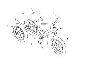
FIG. 1 is a perspective view of a cycle according to
the invention, in its "tricycle" configuration. All the
conventional components of a tricycle can be seen: saddle
1 , handlebars 2 front wheel 3; frame 4, pedals 5 and 6,
rear wheels 7 and 8 linked by an axle 9. In this
configuration of the cycle, the center of gravity of the
cycle is located at axle 9, substantially at the mid-
point thereof, thereby ensuring overall stability. Frame
4 indeed comprises, in the embodiment shown, a forward
portion 14 and a single-beam arm 13.
FIG. 2 shows the cycle of FIG. 1 in a perspective
view, in the "bicycle" configuration. According to the
invention, this configuration is obtained by a simple
transformation of the cycle, as explained below. Those
elements of FIG. 1 will be recognized in FIG. 2: however,
the cycle of FIG. 2 now only has one single rear wheel
10, mounted in a cantilevered fashion on frame 4. FIG. 2
also shows two accessories which can, if necessary, be
mounted on the cycle: small side wheels or stabilizers
11, and a guide arm 12 for pushing and guiding the cycle.
This arm can also be mounted on the cycle in its tricycle
a ~-1.,~~.~,-P,=.si~~H~(.-xuu,cnd,rc~~~~,7-SR4
CA 02234177 1998-07-20
6
configuration shown in FIG. 1. In the bicycle
configuration, the center of gravity of the cycle is on a
line lying in the plane of the front and rear wheels, 3
and 10 respectively. The lateral stabilizers or side
wheels 11 can be fixed to frame 4 (here at the single-
beam arm 13) in conventional manner by a clamp 11'.
Advantageously however, a rubber block or joint can be
provided between clamp 11' and frame 4 thereby allowing
the stabilizers to rotate partially, which allows them to
yield slightly in the vertical direction. The
stabilizers are thus able to closely follow the surface
over which the bicycle is moving, which ensures that the
rear wheel is always kept in permanent contact with the
ground. This avoids the situation where the cycle could
only be resting on the side wheels, with the rear driving
wheel not in contact with the ground, and turning without
propelling the bicycle.
Transformation of the configuration from a tricycle
configuration of FIG. 1 to a bicycle configuration of
FIG. 2 provides a simple, economical and elegant solution
to problems of the prior art. Using one single cycle
decreases financial outlay and facilitates learning.
In an advantageous embodiment of the invention, a
single-beam arm 13 is provided at the rear portion of the
frame, for supporting the wheel or wheels and for
transmitting power from the pedals to the wheel or
wheels. Single-beam arm 13 is laterally offset from the
mid-plane of the bicycle. Rear wheel 10, in the bicycle
configuration, is mounted in cantilever fashion on arm
13, thereby being situated in the mid-plane of the
bicycle. In the tricycle configuration, axle 9 is
mounted on arm 13, so that the mid-point of axle 9 is in
the mid-plane of the bicycle, in other words offset with
respect to arm 13. Arm 13 is described in more detail
with reference to FIGS. 3 to 6.
On FIG. 2, an advantageous method of fixing arms 13
on the forward portion 14 of frame 4 can be partially
seen . a square-section tube 15 is fastened, for example
a ii~,~~,~i:.-.i~ixn =s~~«,.c~~,i,i~.v~,-.,,-.,
CA 02234177 1998-07-20
7
by welding, on the forward portion 14 of frame 4
supporting the saddle and front wheel; this tube acts as
the support for the single-beam arm 13. Single-beam arm
13 has a side tube in the region of its front end, this
side tube engaging in square-section tube 15 ensuring
that single-beam arm 13 is firmly held. The outer cross-
section of the side tube can be square and match the
inner section of tube 15 ensuring play-free assembly. A
shock absorbing system, as described with reference to
FIGS. 3 and 4 can also be provided.
FIG. 3 is a partial view in section of the cycle of
the invention, in the region where the single-beam arm is
fixed to the remainder of the frame, in a horizontal
plane for the cycle in its position of use . On FIG. 3 ,
single-beam arm 13, the end of the right-hand pedal crank
passing through arm 13, square-section tube 15 and side
tube 21 fixed to beam 13 by welding, and the end of a
left-hand pedal crank 22 can be seen. The end of the
right-hand pedal crank 20 is surrounded by a bearing bush
23, bush 23 being extended by a projecting outer cylinder
24 which is assembled by bonding or pinning; the end of
left-hand pedal crank 22 can be fitted into cylinder 24
and be secured by bonding or pinning. It can be arranged
for pedal crank 22 and outer cylinder 24 to be integral
with each other. In this way, the single-beam arm can be
secured by introducing square tube 21 from one side, and
then securing it from the other side by rigidly fixing
(using, for example, a screw) cylinder 24 onto axle 20.
FIG. 4 is a partial view in section of the cycle of
the invention, in the plane IV-IV of FIG. 3, i.e. in a
vertical plane for the cycle in its position of use.
Bearing bush 23 and tube 15 can be seen here. Side tube
21 has a square cross-section and is arranged inside tube
15 but is for example offset by 45° with respect thereto,
so that, seen in cross-section, its outer corners are
substantially on the sides of the square formed by the
inner section of square-section tube 15. Shock absorbers
26 made of an elastic material, (for example elongate
CA 02234177 1998-07-20
8
with a triangle cross-section) are arranged in the spaces
between the tubes. The shock absorbers 26 damp and limit
the pivoting movement of side tube 21 of arm 13 inside
square-section tube 15. This structure provides mounting
with suspension of arm 13, and thus of the rear wheels)
on the front of frame 14. If necessary, means for
restricting pivoting movement of single-beam arm 13 with
respect to the remainder of the frame can also be
provided using, for example, a ball 26' in one or several
of the shock absorbers 26. Also, it can be arranged for
square-section tube 15 to have one internal side the
dimension of which is comprised between the side
dimension of external square-section tube 21 and the
diagonal dimension thereof. Thus, it is ensured that
movement of square-section tube 21 inside square-section
tube 15 are automatically limited.
FIG. 5a is a partial view in section of the single-
beam arm of the invention, similar to the one in FIG. 3
(with square-section tubes), and showing here the
transmission system. On FIG. 5, those elements already
described with reference to FIG. 3 can be seen and are
not described again here. Additionally, a plastic ring
31 preventing the two pedal cranks moving sideways at the
right-hand side is fitted around cylinder 24 and is held
in position, for example by a claw locking washer 25. At
the left-hand side, the two pedal cranks are prevented
from moving sideways by the upset portion 29" of pedal
crank 20 and/or drive sprocket 29 abutting against collar
29' fitted around pedal crank 20, collar 29' being able
to abut against the inner wall of arm 13. In this way, a
pivotal link between side tube 21 and pedal cranks 20 and
22 is achieved. Ring 31 provides axial blocking of tube
15 with respect to side tube 21. Additionally, in a
configuration allowing it to fit into, and come to bear
against square-section tube 15, ring 31 forms a bearing
for the unit comprising pedal cranks 20 and 22 and collar
29', ring 31 being retained by and bearing against drive
sprocket wheel 29, the latter being locked thereto
I irn~,: I i~~-W ~ lxtt=ri nmcnJ,ic I~m7-R/2d
CA 02234177 1998-07-20
9
against rotational and translational movement, and for
example constituting a bearing on the opposite side. In
FIG. 5, there can be seen drive sprocket 29 which is
locked to prevent rotational or translational movement on
pedal crank 20, collar 29' inside single-beam arm 13, and
a drive belt 30, located inside arm 13, and meshing with
sprocket wheel 29, as can be clearly seen in the
description of FIG. 6.
A freewheel mechanism could also be provided by
mounting sprocket wheel 29 on the right-hand pedal crank
via a ratchet mechanism. Similarly, a suitable mechanism
could be provided for braking by backpedaling.
FIG. 5b is a partial view in section of the single
beam arm of the invention, in which the square-section
tubes are replaced by circular-section tubes, the single
beam arm being mounted in the manner indicated in FIGS.
16a and 16b. In the embodiments shown, pedal crank 22
and cylinder 24 are integral. The assembly comprising
the single-beam arm and axle 20 is introduced into a
cylinder 15 at bearings 15' and 15" from one side of the
frame, said bearing being located respectively at
oppossite sides of tube 15. The single-beam arm is then
brought into abutment with bearing 15" and is locked
against translatory movement by the pedal crank and the
cylinder 22, 24 at bearing 15' by means of a screw,
thereby rendering integral pedal crank shafts 20, 22.
The other parts correspond as regards their shape and/or
function to those parts already described in the previous
FIGS., and are not described again here.
The single-beam arm and transmission system can be
assembled as follows. Side tube 21 is welded onto arm
13. Drive belt 30 is arranged inside arm 13 along with
sprocket wheel 29 and collar 29' , and pedal crank 20 is
fitted through sprocket wheel 29 and collar 29'. Next,
pedal crank 20, bearing bush 23 and cylinder 24 are
assembled, the latter being fixed by bonding or pinning.
The unit thus constituted is mounted on the remainder of
the frame by introducing side tube 21 into square-section
a iu~~"~ i r~~_,i ~ i»,a=' ~~a,~.~nnrc nrn_~»_a
CA 02234177 1998-07-20
tube 15 and providing the shock absorbers 26
therebetween, with, if necessary, the ball mentioned
above. Ring 31 and locking washer 25 are arranged on
cylinder 24; next, the left-hand pedal crank is bonded or
5 pinned in cylinder 24. In this way, a rapid and simple
assembly of the unit comprising pedals and single-beam
arm on the forward portion 14 of frame 13 is achieved.
Disassembly is simply achieved for example by removing
the pin from the left-hand pedal crank, removing locking
10 washer 25 followed by ring 31, after which the forward
portion of the frame can be separated from the pedal
crank/single-beam arm/wheel or wheel assembly. Square-
section tube 15 can also be welded onto the lower portion
of frame 14. Tube 15 could also be fixed to the frame by
means of a small plate 63, this embodiment being
described in more detail with reference to FIGS. 15a and
15b. The single-beam arm and transmission system can
also be mounted by fitting the single-beam arm 13 by
means of tube 21 and the shaft of the right-hand pedal
crank 20 into a cylinder 15 fixed onto the frame, after
which the assembly is rendered integral by the other
pedal crank from the other side of the frame.
FIG. 6 shows a longitudinal cross-section of the
single-beam arm in a plane parallel to the longitudinal
plane of the cycle. In FIG. 6, arm 13, a cross-section
of pedal crank 20, sprocket wheel 29 prevented from
rotating and moving linearly with respect to pedal crank
20 (or mounted so as to provide a free wheel effect) and
drive belt 30 can be seen. The arm is closed off at its
front end by a forward plug 32. Arm 13 has,
substantially at its mid-point, a hole 33 allowing, if
necessary, the stabilizing side wheels shown in FIG. 2 to
be mounted. The rear of the arm includes passages for an
axle, and a rear sprocket wheel driven by belt 30, these
parts being described in more detail below. Finally, the
front end of single-beam arm 13 is closed off by a
forward plug 35.
I< '..~ -s 1 s I >( n' _ =s nuccmioc 1997 _ I u/_'d
CA 02234177 1998-07-20
11
The structure of single-beam arm that has just been
described with reference to FIGS. 3 to 6 constitutes an
advantageous embodiment of the invention. Nevertheless,
although its effect facilitates transformation of the
cycle of the invention from a bicycle into a tricycle,
this structure is not indispensable for such
transformation. The invention described with reference
to FIGS. 7 to 10 can also be implemented, without using
the single beam arm of FIGS. 3 to 6.
FIG. 7a shows a partial cross-section in a horizontal
plane of the cycle of the invention, taken at the rear
wheel in a tricycle configuration. On FIG. 7a, arm 13,
rear wheels 7 and 8 and axle 9 can be seen. Axle 9 is
mounted on arm 13 for being driven in rotation by belt 30
and rear sprocket wheel 34. One embodiment of the link
between the axle and single-beam arm 13 is described
later in more detail with reference to FIG. 10. In FIG.
7, axle 9 is constituted by two parts, a tricycle axle 36
and a bicycle axle 37. At one end of the tricycle axle,
a wheel 7 is mounted; at its other end, the tricycle axle
has means 38 for coupling it to bicycle axle 37. Between
wheel 7 and coupling means 38, at around its mid point,
tricycle axle 36 has means 39 for securing it to the
single-beam arm.
At one end of bicycle axle 37, a wheel 8 is mounted;
the other end of the bicycle axle carries means 40 for
coupling it to tricycle axle 36, or to single-beam arm
13.
The overall length of bicycle axle 37 and tricycle
axle 36 in their assembled state, i.e. when they are
coupled together through the means 38 and 40, corresponds
to the distance between the wheels in the tricycle
configuration of the cycle according to the invention.
The length of bicycle axle 37 is such that, when this
axle is mounted on single-beam arm 13, wheel 8 lies in
the mid-plane of the bicycle, represented by line 41 on
FIG. 7. Additionally, the bicycle axle includes securing
means 39 which are situated at a distance such that after
I< I li~~~,. -sl-S I>l)(-..., ~,cinbrc I')')7 _ I I =-1
CA 02234177 1998-07-20
12
the tricycle axis is fastened in place, the two wheels
are symmetrical with respect to this mid-line 41.
Operations on the cycle of the invention are carried
out as follows. For a tricycle configuration, tricycle
axle 36 is mounted on single-beam arm 13 using securing
means 39 (and screw 47) so that it is driven by rear
sprocket wheel 34. Next, bicycle axle 37 is fitted onto
tricycle axle 36, using the coupling means 38 and 40 (and
screw 42). In this way, an axle 9 with two wheels 7 and
8 is obtained. For a bicycle configuration, bicycle axle
37 is directly mounted on single-beam arm 13 using
coupling means 40 and 37' (and screw 47) for it to be
driven by rear sprocket wheel 34. Tricycle axle 36 is
not used.
The operations making it possible to change from one
configuration to the other are simple and fast. Use of
the single-beam arm makes it possible to simplify as much
as possible the coupling means 39 (screw 47) and 40 (and
37' and screw 42) and securing means 38. Clearly, one
could also use a conventional bicycle frame, for example
by providing more complex coupling and securing means,
and incorporating thereinto if necessary, drive sprocket
wheels.
FIG. 7b is a view in partial cross-section, in a
horizontal plane, of one alternative embodiment of the
cycle of the invention, taken at the rear wheel, in a
tricycle configuration. On FIG. 7b, arm 13, and axle 9
can be seen. Axle 9 is mounted on arm 13 so as to be
driven in rotation by belt 30 and rear sprocket wheel 34.
Sprocket wheel 34 is locked in position by interfitting
of two flange plates 34a and 34b into a tube 13 ' . Tube
13' is positioned perpendicularly to arm 13 and is
integral therewith; tube 13' includes a passage allowing
the transmission belt 30 to pass over rear sprocket wheel
34. Between flange plates 34a and 34b, roller bearings
44 and 45 are provided to ensure minimal friction. Axle
9 is constituted by two parts, a tricycle axle 36 and a
bicycle axle 37. At one end of the tricycle axle, a
CA 02234177 1998-07-20
13
wheel 7 is mounted; at the other end, the tricycle axle
has means 38 for coupling it to bicycle axle 37. Between
wheel 7 and the coupling means 38, at about its mid-
point, tricycle axle 36 has means 39 for securing it to
the single-beam shaft, (comprising a spring-mounted
detent or a push-button fastener 47). For a tricycle
configuration, tricycle axle 36 is mounted on single-beam
arm 13, using securing means 39, (and the spring-loaded
detent or push-button means 47) thereby ensuring that it
is driven in rotation by rear sprocket wheel 34. Next,
bicycle axle 37 is assembled onto tricycle axle 36, using
coupling means 38 and 40, (including the spring-loaded
detent or push-button means 42). In this way an axle 9
is obtained with two wheels 7 and 8. For a bicycle
configuration, bicycle axle 37 is directly mounted onto
single-beam arm 13, using coupling means 40, and the
spring-loaded detent or push-button means 37', the latter
thereby occupying the position previously occupied by the
spring-loaded detent or push-button means 47, whereby
axle 37 is driven by the rear sprocket wheel 34.
Tricycle axle 36 is not used.
FIG. 7c is a view in partial section in a horizontal
plane of one alternative embodiment of the cycle of the
invention, taken at the rear wheel, in a tricycle
configuration. Compared to the two previous alternative
embodiments, it will be seen that bicycle axle 37 is
integral with the wheel; this wheel then has a recess
with a bearing, defining two regions 8' and 8" of
different cross-section. The region 8" having the
largest cross-section is designed to be directly mounted
onto the securing means 39 in the bicycle configuration,
while the smaller cross-section region 8' is designed to
receive the tricycle axle. Bicycle axle 37 is integral
at one end with the wheel 8 that it receives, while
carrying at the ocher end the coupling means 40 which are
made up by means 371 and 37" for ensuring coupling to
the cycle frame, and means 37a taking, for example, the
I< I-I~,~... ~._sISI)f)f~_=Xiun-ciuhrc1997_I;/ZJ
CA 02234177 1998-07-20
14
form of a thread, for coupling the tricycle axle at the
coupling means 38.
FIG. 8 shows the coupling means 38 and 40 of FIG. 7
on a larger scale. The coupling means 38 for tricycle
axle 36 are formed by a contraction or neck of the tube
forming the axle inside of which a round threaded portion
can be inserted and fixed. In this way, the end of axle
36 can engage into axle 37. A screw 42 enables axle 36
to be fixed with respect to axle 37. Thus, a simple and
accurate assembly of tricycle axle 36 and bicycle axle 37
is obtained.
FIG. 9 shows the securing means of FIG. 7 on a larger
scale. At its rear end, beam 13 has openings into which
a support cylinder 43 is mounted via anti-friction
bearings, ball races or similar, 44 and 45. The latter
additionally act as end plates for the rear sprocket
wheel 31 which is mounted so as to be locked in rotation
on support cylinder 43. A freewheel mechanism could also
be provided by mounting sprocket wheel 31 on support
cylinder 43 via a ratchet mechanism. One or several
screws) 46 prevent relative translatory movement between
them. Assembly can be done as follows. First, anti-
friction bearings 44 and 45 are assembled in the passages
of beam 13. Next, sprocket wheel 31, over which belt 30
passes, is mounted opposite the passages in arm 13.
Next, support cylinder 43 is introduced through the anti-
friction bearings and the sprocket wheel, the complete
assembly being locked against translatory movement by
screw 46. Other means, such as for example locking
sprocket wheel 31 against translatory movement similarly
to forward sprocket wheel 29 , or using circlips inside
the single-beam arm, etc. can be employed to ensure
locking.
Screw 47 ensures tricycle axle 36 and support
cylinder 43 (which can be threaded) are locked in
rotation and translatory movement. This screw makes it
possible to rapidly assemble and disassemble tricycle
axle 36. Advantageously, a threaded round portion 48 is
o I.n~~,~~.,~-~W W nu~.3xun,cn,nrc~~nn-~a~2a
CA 02234177 1998-07-20
provided in the tricycle axle for receiving screw 42 and
preventing crushing of the tricycle axle. The round
portion 48 can be secured by welding.
FIG. 10 is a sectional view on a larger scale of the
5 cycle of the invention in a bicycle configuration. As
explained with reference to FIG. 7, in this
configuration, bicycle axle 37 is directly mounted on
single-beam arm 13. The bicycle axle can be mounted
using the screw 47, in a similar fashion to the tricycle
10 axle: the end of the bicycle axle is introduced into
support cylinder 43 and screw 47 ensures that bicycle
axle 37 and support cylinder 43 are locked together in
rotation and translatory movement via securing support
37'.
15 As shown in FIG. 10, a sleeve can be provided on the
bicycle axle for mounting a wheel, allowing a 12 inch
wheel to be mounted. Thus the two types of wheel most
commonly used, or more generally any type of wheel,
including those fitted with a freewheel mechanism can be
fitted in an economical fashion. Obviously, the wheel
carrier of tricycle axle 36 can have the same
configuration. The same type of device can be mounted on
the front wheel axle, allowing various wheels to be
mounted.
In FIGS. 8, 9 and 10, the screws can be replaced by
spring-loaded pin or pushbutton-type locking means and
vice-versa, or by any other securing means not
necessarily described herein.
FIG. 11 is a view similar to that in FIG. 8,
illustrating a second embodiment of the coupling means of
FIG. 7; in this embodiment, the end of tricycle axle 49
is not reduced in diameter. Bicycle axle 50 comprises an
adaptor 51, having a small diameter section 52 and a
large diameter section 53. Small diameter section 52 is
designed to be introduced, with minimal play, inside the
end of the tube forming tricycle axle 49. Adaptor 51 is
bonded onto a sleeve 54 on which a wheel can be mounted.
An axial screw 55 passes through sleeve 54, and through
It I n -~el-S I)(u_ _ nmccml>rc 1997- 15124
CA 02234177 1998-07-20
16
adaptor 51. A ring 56 in rubber or a compressible
material is fitted onto the threaded end of screw 55
which projects out of adaptor 51. A nut 57 is screwed
onto the end of screw 55.
Bicycle axle 50 is assembled into tricycle axle 49 by
introducing nut 57, ring 56, and the small diameter
section 52 of adaptor 51 into the end of the tricycle
axle, the large diameter section 53 of adaptor 51
abutting against the end of the tricycle axle. Next,
screw 55 is tightened and ring 56, compressed by nut 57
against adaptor 51 extends against the inner wall of the
tricycle axle thereby ensuring coupling of the two axles.
Disassembly involves the reverse steps.
FIG. 12 is similar to FIG. 10, in a second embodiment
of the coupling means of FIG. 7; bicycle axle 50 is
mounted inside support cylinder 43 like it was inside
tricycle axle 49. However, here, it is the large
diameter section 53 of adaptor 51 which bears against the
inner wall of support cylinder 43. A cover plate 58 can
be provided on support cylinder 43 for hiding nut 57.
FIG. 13 is a view similar to FIG. 8, in a third
embodiment of the coupling means of FIG. 7; the third
embodiment is similar to the second embodiment, except
that nut 57 is replaced by nut 60 welded inside the
tricycle axle. Ring 56 is also replaced by a simple
washer 61. Assembly and disassembly involves simply
screwing or unscrewing screw 55 into or out of nut 60.
FIG. 14 is a view similar to FIG. 10 in a third
embodiment of the coupling means of FIG. 7; here a
releasable nut also constituting a cover is provided.
Nut 62 is provided at one end of support cylinder 43 and
screw 55 of the bicycle axle is screwed into nut 62,
passing through support cylinder 43. The bicycle axle is
fixed onto cylinder 43, the end of sleeve 54 bearing
against cylinder 43.
FIGS. 15a and 15b show one way of fixing square-
section tube 15 onto frame 14. A small plate 63 is
welded onto the lower portion of frame 14, the plate
CA 02234177 1998-07-20
17
having a hole 64 at one end which matches an identical
holes 65 formed in the portion of the frame opposite it.
The two are kept together by, for example, fitting a
quick-fit nut 66 through holes 64 and 65. Square-section
tube 15 has a second small plate 67 designed to match the
shape of plate 63 welded onto it. One end of plate 67 is
folded to form a channel 68 and the other end carries a
hole 69 which is identical to, and designed to come
opposite holes 64 and 65. By inserting small plate 63
into channel 68, the two plates can be rendered integral
by a screw screwed down into the quick-fit nut referred
to above. Disassembly involves the reverse operations.
FIGS. 16a and 16b show one embodiment in which
single-beam arm 13 is secured to the forward portion 14
of the frame by means of an external shock absorber 70,
FIG. 16b corresponding to a sectional view of FIG. 16a
along line C-C. The drive mechanism passes through the
single-beam arm 13, the mechanism being engaged inside a
cylinder 15 welded at the lower part of the forward
portion of the frame 14. An external shock absorber 70
links the single-beam arm and the frame, the shock
absorber being secured at each end by engaging it over
suitably located pins 71, 72. When the drive mechanism
is being inserted into place, the shock absorber is also
mounted by slipping it over the pins, and is retained in
this position as it has the single-beam arm on one side,
and the frame on the other side.
FIGS. 17a and 17b show a top and side view of one
manner of fixing the lateral stabilizers or side wheels
11, which are mounted by interfitting two tubes 71a and
71b, which, for example, have a square cross-section.
Equidistant holes drilled in the square section tube,
rigidly fixed to the single-beam arm, can be provided,
able to receive a spring-loaded detent or push-button
located on the interfitted tube. This allows height
adjustment of the lateral stabilizers or side wheels, and
ensures they can be fitted (and removed) as well as
adjusted, in a very simple and easy manner.
IL I I~u~~~ :~ -sl S I)()o _ °t n,vcinlue I~P77- 17/.4
CA 02234177 1998-07-20
18
The embodiments of the coupling means each have their
own advantages, and can all be employed for implementing
the invention and, if necessary, be combined.
Obviously, the invention is not limited to the
embodiments described and illustrated but may be subject
to numerous variations available to those skilled in the
art without departing from the scope of the invention.
For example, the single-beam arm is not necessarily of a
one-piece construction and can also be formed by
assembling several parts. The wheel can be suspended in
a cantilevered fashion, or the transmission can be offset
with respect to the longitudinal plane of the cycle
without necessarily employing a single-beam arm of the
type in FIGS. 3 to 6.
Means other than the coupling means 38 and 40 can be
employed as can other securing means different from the
securing means 39 described above, depending on the
structure of the cycle frame, and the transmission means
are not necessarily formed by a belt 30.
Finally, the invention clearly applies to other types
of product, such scooters, pedal carts and to any type of
wheeled toy. The term 'bicycle" in this specification
covers not only the conventional bicycle, but more
generally any type of product having an axle with a
single wheel: the term could thus also cover a scooter
with a single rear wheel. Similarly, the term "tricycle"
covers any type of product having an axle with two
wheels: the term could thus cover a scooter having two
rear wheels.
The frame of the cycle, as well as the drive system
and the single-beam arm, can additionally be employed for
providing non-transformable cycles; using the same
structure as a basis, it is thus possible to provide
three separate products , a bicycle, a tricycle, and an
adaptable cycle. Notably, it is possible to obtain a
bicycle carrying the single-beam arm according to the
embodiment of FIG. 5b and/or according to FIGS. 16a/16b,
with, optionally, the lateral stabilizers which can be
~t ~-: ,:,-,~ ~ m » _ =,, ~,.., «"~"~ n~a, - ~ ~~-a
CA 02234177 1998-07-20
19
secured according to the embodiment described above. The
single-beam arm, the manner of securing it onto the frame
via the transmission system, the built-in drive belt
transmission securing by means of an external shock
absorber, the manner of attaching the lateral stabilizers
or side wheels (by interfitting or by means of a clamp
provided with a rubber block or dumper) are alternative
embodiments which are all inventive per se and which can
be applied to all the cycles.
IL : ~~IInCVI'SI)()('7Rntn~CmbrCl')'J7-I')/=4