Note: Descriptions are shown in the official language in which they were submitted.
CA 02234525 1998-04-09
17GE05725
DIItECT-COOLED DYNAMOELECTRIC MACHINE STATOR
CORE WITH ENHANCED HEAT TRANSFER CAPABILTTY
TECHNICAL FIELD
This invention relates generally to dynamoelectric machines, and
particularly to a means of improving the rate of heat transfer within cooling
ducts
used to ventilate the stator core of such machines.
BACKGROUND
As is commonly understood by those practiced in the art of electrical
generator design, the capacity of current machines for power generation is
constrained by physical size, which is to be minimized in order to also minifi
e
cost. Designers are further cognizant of size and weight limitations imposed
by
domestic and foreign ground transportation systems.
It is also commonly understood that magnetic and resistive losses within
the stator generate heat which must be dissipated in order to avoid electro-
mechanical failure, and that these losses pose a serious constraint on the
capacity
of a machine of given physical dimension. The high thermal capacity and
thermal
conductivity of gaseous hydrogen have been successfully exploited in the past
by
manufacturers seeking to satisfy customer's needs for increased capacity,
within
the constraints of physical shipping envelope and thermal loading. For those
customers who are unwilling to suffer the additional cost and complexity of
hydrogen cooling, manufacturers must devise the means to manage increases in
thermal loading that accompany their efforts to coax additional capacity from
machines of a given physical dimension.
CA 02234525 1998-04-09
- 2 - 17GE05725
The current state of the art is typified by a radial duct formed by separating
stator core laminations by radially arranged inside spacer blocks, as shown in
Figure 1 and as described further below. Gaseous fluid flow is encouraged to
progress in a radially-inward direction from a plenum area posterior to the
stator
core to the rotor/stator air gap (a radially-outward flow direction is also
possible).
These radial ducts are arranged in what is known as packages; a package being
comprised of several steel laminations (seventy, in one example) stacked one
atop
the other. The packages are separated by the radially oriented inside spacer
blocks, which, along with adjacent laminations of adjacent packages, define
the
radial ventilation ducts.
The fluid flow within the core lamination packages removes ohmic losses
and magnetic losses by convective heat transfer. Those practitioners
possessing
ordinary levels of skill in the art will recognize this configuration as
common, and
will additionally recognize this flow to be turbulent in the fluid-dynamic
sense in
the tooth (radially inner) region of the duct. The inventors are also not
aware of
any previous effort to augment heat transfer in the stator core duct by means
of a
turbulence-enhancing or surface-area-enhancing devices. The inventors are not
aware of any other application of turbulators to the stators of
turboalternators;
although the use of turbulators to increase the cooling rates within the
interior
flow passages of aircraft jet engine turbine blades is known.
DISCLOSURE OF THE INVENTION
The invention has an important application in increasing the power output
capability of turboalternators of a given physical dimension, resulting in a
reduction in production cost per MW of output. Alternatively, the invention
permits a reduction in physical dimension of machines of a given rating, which
likewise results in a cost savings. A third possible application of the
invention is in
CA 02234525 1998-04-09
- 3 - 17GE05725
the reduction of parasitic cooling flow pumping loss and windage, resulting in
an
improvement in overall efficiency, and a reduction in perceived noise level.
The
invention entails only a minor modification of the existing stator core design
and
requires the addition of no new components. The invention has an immediate
application to a large class of dynamoelectric machines which employ the
gaseous
flow of air or hydrogen, (and potentially to other gases such as helium) for
cooling.
In the exemplary embodiments disclosed herein, the invention comprises of
a plurality of protuberances, known hereinafter as "turbulators", but also
known in
the art of heat transfer as ribs or trips, which extend into the stator core
cooling
ducts. The primary function of the turbulator is to enhance the degree of
turbulent, fluid-dynamic mixing between heated fluid adjacent to the duct wall
and
relatively cooler fluid near the duct centerline. This enhanced level of
mixing
brings cooler fluid in contact with the duct wall, creating greater potential
for heat
transfer. A secondary feature of the turbulated duct is an increase in surface
area
exposed to the convective cooling gas. A third feature is the creation of
areas
within the duct in the vicinity of the turbulator of local fluid-dynamic
separation
and reattachment at which local enhancement of heat transfer occurs.
The invention described in this disclosure thus meets the requirements
noted above through increased rates of heat removal from the armature winding
of
the generator of large capacity electrical turboalternators. The invention
also
meets the increasingly important need for inventory control, in that no new
components are introduced into the generator as a result of the invention.
Lastly,
the invention meets the need for broad applicability across an entire product
line,
as it can be appGed in conjunction with any gaseous or liquid cooling medium
presently in use or reasonably anticipated for future application by those
skilled in
the art.
CA 02234525 1998-04-09
- 4 - 17GE05725
Thus, this invention seeks a significant reduction in the temperature drop
between the stator conductor tums and the cold gas temperature for a given
expenditure in parasitic cooling flow pumping loss. This greater capability
may be
exploited to design generators of greater output for a given physical
dimension.
Alternatively, the invention permits a reduction in parasitic cooling flow
pumping
loss and windage, resulting in an increase in efficiency and a reduction in
noise, for
a given rating and physical dimension.
This invention also offers the customer increased output for a given
machine size, particularly in cases where the capacity of a unit is near the
transition
point between cooling technologies. For example, this invention may enable the
application of an air-cooled machine at a rating which would otherwise have
called
for a hydrogen-cooled machine. This is a commercially attractive feature,
since,
many aistomers seek to avoid the added cost, safety concern, and complexity of
hydrogen cooling. As second example, this invention may enable the application
of a hydrogen-cooled machine at a rating which would otherwise have called for
a
liquid-cooled stator bar design. In this case, the cost and complexity of a
deionized water slcid is obviated.
A particular advantage of the invention is that it is a completely passive
heat transfer augmentation method, requiring no chemical additives, acoustical
input or other active stimuli. The invention is especially easily
manufactured,
requiring only a simple slitting and forming operation as one of the stages of
forming the lamination in a punch press. The invention does not require
precise
tolerances in order to function as expected. Lastly, the invention is
applicable to
the entire product line, for both air-cooled and hydrogen cooled machines, and
in
fact is appGcable to any liquid or gaseous cooling medium.
CA 02234525 1998-04-09
- 5 - 17GE05725
In a first embodiment of the invention, the turbulators are formed in the
yoke or radially outer region of one of the two laminations which form a
respective coolant passage. The turbulators are radially spaced from each
other,
within each of the radial ducts. The turbulators extend generally
perpendicular to
the flow direction, and extend into the duct approximately 20% of duct height
(i.e., the dimension between adjacent laminations as defined by the inside
spacer
blocks).
In a second and presently preferred embodiment, similar turbulators are
formed primarily in the tooth regions of the respective lamination, extending
only
partially into the yoke region.
In a third embodiment, each turbulator is formed by a pair of tabs oriented
in a substantial, V-shaped arrangement. The turbulators are provided only in
the
yoke region, but could be provided in the tooth region as well.
In a fourth embodiment, each turbulator is formed by a single fin or tab
aligned with the coolant flow, with the turbulators extending radially
throughout
the yoke and tooth regions. This arrangement causes less pressure drop
relative to
the turbulators mounted transverse to the flow.
In all of the described embodiments, an increase in heat transfer is expected
due to the roughness associated not only with the turbulators per se, but also
with
the cavity in the duct surface that results from forming the fin or turbulator
from
the lamination.
In each case, the tab or fin which forms all or part of a turbulator is cut
and
then bent out of the plane of the lamination, at an angle ranging from about
30 to
about 90 , with a preferred range of about 30 to about 45 .
CA 02234525 1998-04-09
" 6 ' 17GE05725
Thus, in its broader aspects, the invention relates to a dynamoelectric
machine stator core assembly wherein adjacent packages of stacked laminations
are separated by a plurality of radially extending spacer blocks, and wherein
each
adjacent pair of spacer blocks define in cooperation with adjacent axially
spaced
laminations, a cooling duct, the improvement comprising a plurality of
turbulator
elements in each cooling duct, each tubular element extending into said duct
from
one side of said adjacent axially spaced laminations.
Other objects and advantages of the invention will become apparent from
the detaited description which follows.
BRIEF DESCRIPTION OF THE DRAWINGS
FIGLTRE 1 is a partial side elevation of a conventional stator core
lamination assembly;
FIGURE 2 is a sectional view of a spacer block incorporated in the
assembly shown in Figure 1;
FIGURE 3 is a partial side elevation of a stator core lamination assembly in
accordance with a first embodiment of the invention;
FIGURE 3A is an enlarged partial perspective of a turbulator shown in
Figure 3;
FIGURE 4 is a partial side elevation of a stator core lamination-assembly in
accordance with a second embodiment of the invention;
CA 02234525 1998-04-09
-7- 17GE05725
FIGURE 4A is an enlarged detail taken from Figure 4;
FIGURE 4B is a section taken along the line 4B-4B of Figure 4A;
FIGURE 5 is a partial side elevation of a stator core lamination assembly in
accordance with a third embodiment of the invention;
FIGURE 5A is a partial perspective of a turbulator shown in Figure 5; and
FIGURE 6 is a partial side elevation of a stator core lamination assembly in
accordance with a fourth embodiment of the invention;
BEST MODE FOR CARRYING OUT THE INVENTION
With reference to Figure 1, a portion of a conventional stator core
lamination assembly 10 is shown. The assembly may comprise approximately 70
discrete laminations within a"package" 12, Except as noted below, these
laminations are typicaUy 0.014 to 0.018 inch thick, and a package of
laminations is
approximately 1 to 3 inches thick. A plurality of inside spacer blocks or rods
16
are secured to the "outermost" lamination 14 of the package; and extend
radially
along the yoke portion 18 of the core lamination, and longer spacer blocks or
rods
which extend radially not only along the yoke region 18, but also along the
radially inner tooth region 20. The lamination to which the inside spacer
blocks
are welded is thicker than the remaining laminations in the package, typically
0.025 inch thick. The inside spacer blocks 16 have a generally I-beam shape in
cross section (see Figure 2), with the flat sides engaging adjacent stator
core
lamination packages to thereby define a plurality of radially extending
coolant
passages or ducts between adjacent spacer blocks. Depending on the particular
cooling arrangement, coolant flow may be in a radially inward or radially
outward
direction. Typically, the inside spacer blocks have a height of about .250
inches,
CA 02234525 1998-04-09
_ g _ 17GE05725
which also then defines the height of the coolant passage. The width of the
spacer
blocks is also about .250 inches.
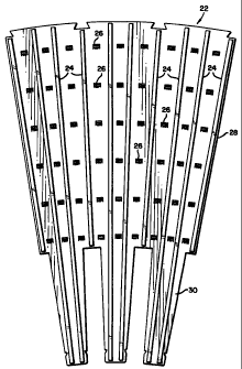
Turning now to Figure 3, a first embodiment of the subject invention is
illustrated. The stator core lamination package 22 is generally similar to
that
shown in Figure 1, in that radiatly oriented coolant passages are formed by
radially
extending spacer blocks 24 and two adjacent laminations of adjacent lamination
packages. Figure 3 also illustrates the location and orientation of a
plurality of
turbulators 26 within each of the radially extending cooling ducts. Thus, it
can be
seen that the turbulators 26 are located at regularly spaced intervals in the
radial
direction, and follow generally the curvature of the stator core assembly in a
circumferential direction. It is also noted that the turbulators 26 appear
only in the
yoke region 28 of the stator core lamination assembly, and not in the tooth
region
30.
With reference to Figure 3 A, it may be seen that the turbulators 26 are
formed in only the single lamination 32 of the many laminations 32, 32a, 32b,
32c,... in the package which forms one wall of the cooling duct. In this
embodiment, the turbulator 26 may have a width of 0.380 inch and is oriented
90
relative to the plane of the laniination assembly. It will be appreciated,
however,
that the turbulators may be formed at an angle of between, for example, 30 or
45
relative to the plane of the lan-Anation as described below in connection with
Figure 4B. These turbulators are formed by ribs or tabs which are punched out
of
the lamination and then bent so as to extend into the coolant passage. This,
of
course, is done prior to assembly of the respective package. The lamination in
which the turbulators are formed has a thickness of about .025 inch, while the
other laminations 32a, b, c, etc. in the package have a wall thickness of
about .014
inch. As in the conventional practice, there are about 70 laminations in each
package. The ratio between the radial spacing of the turbulators (e.g., about
CA 02234525 2006-09-14
17GE05725
-9-
0.375 inch) to the height of the turbulators (e.g., about 0.025 inch) is
preferably about
15 but may be between about 5 and 20.
Note that no spot welds are required to attach the turbulators. This not only
obviates the extra manufacturing step of spot welding, but also precludes the
possibility of the turbulator separating from the duct surface and traveling
about the
generator subject to the strong magnetic fields. The turbulators could,
however, be
welded directly to the laminations comprising the duct.
The inside spacer block 26 in accordance with this invention have a
generally rectangular cross section and a height of approximately 0.125 inch.
With
turbulators having a height of about .025 inch, the turbulators extend into
the coolant
passage about 20% of the height of the passage, or about 10% of the duct
hydraulic
diameter.
In accordance with conventional practice, the lamination 32 forming the
wall of the coolant passage is generally made of carbon steel, while the
remaining
laminations 32a, b, c, etc. in the package are formed of silicon steel. It
should be
noted here, however, that the selection of materials and the material
thicknesses in
accordance with this invention generally do not vary over those same
dimensions/parameters in the prior art arrangement as illustrated, for
example, in
Figure 1.
Turning now to Figures 4, 4A and 4B, another and preferred embodiment
of the invention is illustrated wherein turbulators 34 are formed in a
lamination 36,
primarily in the tooth regions 38 but extending partially into the yoke region
40.
Again, the turbulators are formed in radial passages between interior radially
arranged spacer rods 42, as further defined by adjacent laminations of
adjacent
packages. The radial spacing between turbulators and the manner in which the
CA 02234525 1998-04-09
- 10 - 17GE05725
turbulators are formed are otherwise similar to the description provided above
in
connection with Figures 3 and 3A One change, however, is that the turbulators
34 are punched out of the lamination 36 such that the turbulator extends at a
30 -
45 angle with respect to the lamination proper. This is done primarily to
facilitate
the cut and punch process by which the turbulators are formed. Maximum
protrusion of the turbulator 34 into the coolant passage is again about .025
inch.
Turning now to Figures 5 and 5A, yet another embodiment of the
invention is illustrated wherein the turbulators 44 are formed in a respective
lamination 46 of a respective lamination package by a pair of tabs 48 oriented
to
produce substantially V-shaped vortex generators. The arrow indicates normal
orientation of the turbulators with respect to flow, but the orientation may
be
varied. The radial spacing between turbulators 44 is larger than with the
turbulators 34, reflecting the radial component of the V-shape. Otherwise, the
general arrangement of the turbulators within the yoke region of the stator
core
lamination between adjacent spacer blocks 50 is similar to that illustrated in
Figures 3 and 3A In this instance, however, the punch press operation is
employed to cut and bend a pair of elements to create the above noted
substantial
V-shape. This embodiment can be expected to provide even fiuther increases in
heat transfer in light of the roughness associated with the larger cavity 51
in the
duct surface that results from forming the fin or turbulator from the
lamination.
With reference now to Figure 6, yet another arrangement of turbulators is
illustrated wherein, not only do the turbulators 52 extend radially along the
stator
core lamination 54 of a respective lamination package in both the tooth and
yoke
regions 56, 58, respectively, but the turbulator orientation has been changed
so
that the tab extends parallel to the spacer blocks 60 and parallel to the
direction of
flow.
CA 02234525 1998-04-09
- 11 - 17GE05725
It is noted that in each of the above described embodiments, turbulators
are shown to extend from one side only of the respective cooling ducts. The
turbulators could extend, however, from both sides of the ducts, in either
aligned
or staggered relationship in the radial direction.
Testing of the turbulated coolant ducts similar to the preferred
arrangement illustrated in Figures 4, 4A and 4B, demonstrate that heat
transfer
performance at the turbulated wall is about twice as good as that found in
smooth
flow coolant passages.
While the invention has been described in connection with what is
presently considered to be the most practical and preferred embodiment, it is
to be
understood that the invention is not to be limited to the disclosed
embodiment, but
on the contrary, is intended to cover various modiScations and equivalent
arrangements included within the spirit and scope of the appended claims.