Note: Descriptions are shown in the official language in which they were submitted.
CA 022346l6 l998-04-l4
W O 97/14117 PCT~US96/16366
AlnD ~CE~OD ~OR R~R~r~l~, Q~-~C ~ D
YRI ~ lNG PO~GE I ~ IC~A O~ rO~
Nlc~L FIELD OF ~ E lNV~N'l'lON
This invention relates, in general, to printing
postage indicia on mail. ~ore specifically, ~he
invention relates to a system and method ~or creating
postage indicia in conjunction with a word processing
document and ~or displaying andlor transferring the
indicia on ~he front of an envelope ~he system will
calculate the postage due and personalize the ~ostage
indicia.
SU~Ill~TEsHEET(RuLE26
CA 022346l6 l998-04-l4
W O 97/14117 PCT~US96/16366
~A~KGROUND OF THE INVENTION
The use of word processors running on general
purpose computers is so common place today as to be
taken for granted. Children, as well as adults, use
such word processing programs to create, format and
print (in selected colors, fonts and size) every
conceivable type of document. These systems are used to
create all manner of designs and to print the creations
on all manner of printable material in addition to
paper. One example for the use of such processors that
has become very popular is to use them for the creation
of paper checks. This use is typically in conjunction
with an accounting program which mimics a user's
checkbook. Another use is the creation of T-shirt
designs and the subsequent printing of such T-shirts
(or other material) under control of the user.
Often, the document that is created by the user in
the processor (for example, a letter or a check) is
then mailed to some other location. This entails the
placing of the document (or other material) in a
mailing container (envelope), addressed, and supplied
with sufficient postage.
Many of the programs in use today print the
mailing address (as taken from the document) on labels
which are printed in conjunction with the creation of
the document. These labels then are peeled off the
document and transferred to the outside of the mailing
envelope to save the user time and to avoid placing the
envelope in the printer or otherwise addressing the
envelope.
However, using such system the user still must add
postage to the mailing envelope manually or the user
must run the mailing container (envelope) through a
postal meter. At best, this is one additional step.
At worst, in the case of a nonconforming mailing
CA 022346l6 l998-04-l4
W O 97/14117 PCTrUS96/16366
,
container such as a carton, several additional steps
are required.
Furthermore, the customer is limited in the
~ graphic configuration of the postage applied to the
letter to those configurations printed and sold by the
Post Office. Currently, the customer does not have the
ability to create a customized postage indicia that
would correspond to the message on a particular
document.
Accordingly, there is a need in the art for a
system and method that provides for the printing of an
appropriate amount of authorized postage by the same
general purpose processors that allow the customer to
create documents.
Thus, it is an object of the present invention to
provide a means for the customer to enter the
appropriate rate determining information such as the
address to which the customized greeting card is being
sent, what class of mail is being used, etc., and have
the processing system that formats and prints a
document to concurrently calculate the appropriate
postage for the greeting card and print the appropriate
postage for that document at the same time the document
is being printed.
CA 022346l6 l998-04-l4
W O 97/14117 PCTrUS96/16366
,
SUMMARY OF THE INVENTION
The present invention fulfills the needs discussed
above by disclosing a method and a system whereby a
customer may automatically calculate the correct amount
of postage, print the correct amount of postage,
personalize a selected stamp indicia, and print address
labels at the same location where the customer
generates a customized greeting card.
In accordance with one aspect of the present
invention, a general purpose computer based system is
disclosed which operates in conjunction with a
conventional word processing program, check creation
program or with any other program that can format and
control the printing of user controlled documents to
allow the user to automatically calculate the correct
amount of postage for that document and to print that
postage at the same time the document is being printed.
In one embodiment, the printed postage indicia is
put in a corner of the document so that after the
document is placed in an envelope, the postage will
show through a glassine "window" created in the
envelope.
In another embodiment, the postage indicia is
printed on a transfer sheet and physically transferred
to the outside of the mailing envelope or package.
The discussed system can also generate postage
which includes a personalized postage indicia which may
also contain an encrypted message, such as a PostNet
zip+4 bar code, as a function of mailing parameters
entered into the system and particular to the
associated document.
one technical advantage of this invention is that
a printer can create a document as well as the postage
to mail that document during one pass across the blank
writing medium.
CA 022346l6 l998-04-l4
W O 97/14117 PCTrUS96/16366
A further advantage of this system is that the
user can select a postage indicia from a menu of
available graphic configurations to correspond with the
~ type of document being generated and the system will
print the postage as part of the document.
Yet another advantage of this system is that the
postage generated by the system will have a PostNet
Zip+4 bar code printed on it which makes that piece of
mail easier to sort, route and deliver.
The foregoing has outlined rather broadly the
features of the present invention in order that the
detailed description of the invention that follows may
be better understood. Additional features of the
invention will be described hereinafter which forms the
subject of the appended claims. It should be
appreciated by those skilled in the art that the
conception and the specific embodiments disclosed may
be readily utilized as a basis for modifying or
designing other structures for carrying out the same
purposes of the present invention. It should also be
realized by those skilled in the art that such
equivalent constructions do not depart from the spirit
and scope of the invention as set forth in the claims
of the invention.
CA 02234616 1998-04-14
W O 97/14117 PCT~US96/16366
BRIEF DESCRIPTION OF THE DRAWINGS
For a more complete underst~n~;ng of the present
invention, and the advantages thereof, reference is now
made to the following descriptions taken in conjunction
with the accompanying drawings, in which:
FIGURE lA illustrates a processor-based system for
implementation of the present invention;
FIGURE lB illustrates several embodiments of the
postage storage device;
FIGURE 2 illustrates an embodiment of user
instructions and screen prompts utilized by the present
invention to interface with a user when installing the
program on the processor-based system for
implementation of the present invention;
FIGURE 3 illustrates an embodiment of a user
registration form;
FIGURES 4A-4B illustrate a display screen utilized
by the present invention to interface with a U.S. Post
Office employee when replenishing postage within the
present invention;
FIGURE 5 illustrates a flow diagram of the
replenishing process;
FIGURE 6 illustrates a preferred embodiment of the
security techniques utilized within the present
invention;
FIGURES 7A and B illustrate a flow diagram for
controlling the removal of data from the memory of a
postal storage device;
FIGURE 8 illustrates how a postage button is
encoded;
FIGURE 9 illustrates a flow diagram of the
operation of the present invention within a card
generating system;
CA 022346l6 l998-04-l4
W O 97/14117 PCTrUS96/16366
FIGURE 10 illustrates one embodiment of a display
~ interface provided to a customer for selecting a type
of greeting card;
FIGURE 11 illustrates one embodiment of a display
interface provided to a customer for selecting a style
of greeting card;
FIGURES 12A and B illustrate one embodiment of a
personalized greeting card;
FIGURE 13 illustrates a display interface provided
to a customer when accessing the present invention on a
card generating system;
FIGURE 14 illustrates one embodiment of a display
interface provided to a customer for selecting a type
of postage indicia;
FIGURE 15A illustrates one embodiment of a display
interface provided to a customer for selecting a
specific postage indicia that can be personalized by
the customer;
FIGURE 15B illustrates a postage indicia that has
been personalized;
FIGURES 16A and B illustrate two embodiments of
print formats of the information entered into the
"E-STAMP" program;
FIGURE 17 is a flow chart of system operation
working in conjunction with another word processing
program;
FIGURE 18 is a view of a document having on it a
transfer mechanism for moving the printed indicia from
the document to the front of the envelope;
FIGURE 19 shows a check with the postage indicia
printed on the face of the check; and
FIGURE 20 shows an envelope having a transfer
mechanism for showing the postage to a viewer outside
the envelope.
CA 022346l6 l998-04-l4
W O 97/14117 PCT~US96/16366
, .
DETAILED DESCRIPTION OF THE INVENTION
The present invention provides for a portable
postage storage device, described in more detail below,
that can be coupled to a general purpose
processor-based system that interacts with a customer
to generate a document, or other piece of mail.
The present invention further provides for a
method and system, described in co-pending U.S.
application serial no. 08/263, 751 and incorporated
herein by reference, for automatically calculating the
appropriate amount of postage for a piece of mail,
printing that amount of postage and deducting the
printed amount of postage from the total amount of
postage stored within the portable postage storage
device. In addition, the present invention allows the
user to retrieve, select, personalize and print postage
indicia .
The present invention will allow an amount of
authorized postage to be loaded into a portable postage
storage device by the U.S. Post Office via a
processor-based system hereinafter referred to as the
"POSTAGEMAKER" program. Although reference is often
made to the U.S. Post Office, the present invention may
be implemented within any country and with respect to
any postal system.
The loaded postage may be accessed and a portion
of that postage retrieved via a program stored on a
processor-based system, such program hereinafter
referred to as the "E-STAMP" program. The E-STAMP
program may be stored on a processor-based system that
also contains a document generating system. The
document generating system may be used to generate
customized mail, as for example personalized greeting
cards.
CA 022346l6 l998-04-l4
W O 97/14117 PCTrUS96/16366
A detailed discussion of the inventive concepts of
this invention will now be made with respect to FIGURES
17 through 20. A detailed discussion of the general
system operation is contained in this disclosure
hereinafter with respect to FIGURES lA through 16B.
The user is referred to the subsequent discussion to
gain an underst~n~;ng of how the general purpose
processor works in conjunction with the portable
processor to control the dispensation and creation of
lo postage indicia.
Referring now to FIGURE 17 two embodiments of the
invention are shown, one proceeding from check
processing program 1701 and the other from word
processing program 1702. It should be noted that these
programs are well-known in the art and are typical of
the may application types available for document
preparation. For example, a typical well-known check
processing program is available to the general public
from Intuit Corporation and is licensed under the trade
name "Quicken". Available to every user with the
"Quicken" program is a manual of operation of the
"Quicken" system, which is hereby incorporated by
reference herein.
Similarly, a typical well-known word processing
program could be, for example, the "Word" system from
Microsoft. Also included with each word processing
program from Microsoft is a manual of operation giving
extensive details of the operation of the "Word" system
from a user's perspective. Such manual is hereby
incorporated by reference herein.
Decision box 1703 makes a determination of whether
the automatic postage box is on. The automatic postage
box, for example, would be a designation made by the
user of either the check processing program or the word
processing program contained within that system any
information being co- ;cated to a decision point.
CA 022346l6 l998-04-l4
W O 97/14117 PCT~US96/16366
Obviously, if the answer is no, the program then
would skip to the regular check processing program or
word processing program or whatever other program is
being run as shown in box 1704.
If the answer is yes, then the user is queried in
box 1705 as to whether he/she wishes to use a database
of indicia that have already been created.
If the answer is no, the program skips to box
1709. If the answer is yes, then the program goes to
box 1706 where the user is asked whether the user
wishes to create his/her own indicia or whether the
user wishes to modify indicia.
If the user wishes to create his/her own indicia,
then the user is referred to box 1707 where a drawing
program is provided for the creation of the indicia.
One such program can be the macromedia free-hand
program which is available to the general public and
which comes with an operating manual, which operating
manual is hereby incorporatçd by reference herein.
If the user, as shown in box 1706, simply wishes
to modify an existing indicia, then the user is
referred to box 1708 where the existing database is
made available and the user selects the indicia of the
user~s choice and either uses it directly or modifies
it.
When such modification is finished, the user is
then referred back to box 1709 and determination is
made as to whether this is a draft. The reason for
this is that if it is a draft, there is no need to
print the postage thereon.
If it is a draft, then the program moves to box
1710 and returns to the controlling word processor
program where regular formatting and printing is
controlled.
However, in box 1709, if this is a final version,
a determination is made via box 1711 as to whether this
CA 02234616 1998-04-14
W O 97/14117 PCTnUS96/16366
11
is a check. If it is a check, then the amount of
postage is calculated allowing for the envelope size
and weight in box 1713.
~ However, if this is a word processing program, the
page count is obtained via box 1712 from the
controlling word processor program in box 1702 so that
the system can, based upon the number of pages,
calculate the amount of postage that will be due and,
as shown in box 1713, allowing for the envelope size
and weight will determine the amount of postage to be
printed.
Box 1714 prints the postage indicia on a transfer
media on the letter or prints it directly on the letter
for situations where the postage is going to be used in
a glassine-type envelope or otherwise transferred to a
user without a peel-off label, as will be discussed.
In FIGURE 19 there is shown a check 1900 with
sender's address location 1903, payee's address box
1902 and having a place 1901 for the printing of the
postage.
Location 1901 is where the postage indicia is
printed. However, located at Location 1901 can be a
label which is peeled off and which thereby allows the
user to transfer the postage to the outside of an
envelope, such as envelope 2000. Location 1901 also
could be an ink type that when printed on establishes a
special transfer facility such that when the check is
placed in an envelope of the proper type, a like
position, such as position 2001 of envelope 2000 shown
in FIGURE 20 is in juxtaposition with Location 1901
will react with the ink medium or other special
transfer facility of 1901, thereby presenting to a
viewer on the outside of the envelope, the postage
indicia on the inside.
In this manner a transfer occurs between postage
printed on check 1900 and the outside of envelope 2000
CA 022346l6 l998-04-l4
W O 97/14117 PCT~US96/16366
12
without the need for removing and repasting the label.
This transfer could occur as a chemical reaction or
otherwise under perhaps heat control as generated by a
user's finger or by any other mechanism desired. Of
course, box 2001 of FIGURE 20 can be a glassine window
which allows a viewer to see the postage printed at
position 1901 of check 1900.
FIGURE 18 shows a letter 1800 having a body of the
letter in 1803 with a postage indicia label 1801 and an
address label 1802. As just discussed, postage indicia
label 1801 could be removed and positioned on the
outside of an envelope or the indicia could be
imprinted directly on the envelope and the envelope
folded such that position 1801 of letter 1800 will show
through window 2001 of envelope 2000 in FIGURE 20.
Address label 1802 could be utilized in the same
manner or the address label 1802 not printed at all and
a viewer view the name through a glassine window such
as window 2002 of envelope 2000 in FIGURE 20.
General System OPeration
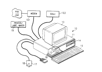
Referring to FIGURE lA, there is illustrated a
processor-based system 10 utilized for implementing the
present invention, specifically the aforementioned
E-STAMP and POSTAGEMAKER programs. System 10 includes
chassis 11 enclosing processor ("CPU") 12 and disk
drive 14. System 10 is a general purpose computer,
such as an IBM compatible (or Apple MacIntosh)
controlled by any general purpose operating system such
as DOS or UNIX. Coupled to CPU 12 is display 13,
keyboard 15 and mouse 16.
Furthermore, system 10 is adapted for coupling
with a postage storage device 18, such as the preferred
embodiment touch memory utility ("TMU") button 182
illustrated in FIGURE lB. Postage storage device 18 is
coupled to the processor-based system 10 through a
postage storage device receptor 17.
CA 022346l6 l998-04-l4
W O 97/14117 PCTrUS96/16366
13
The postage storage device may be any memory
device having some residual data capability, where that
memory device can provide sufficient security measures
to efficiently limit access to the memory of the device
to authorized users. For example, since algorithms can
be used to control access to the memory device, a
standard "diskette" can be used if desired.
The preferred embodiment, TMU button 182,
incorporates a small disk having a memory. TMU
button 182 is a small, light-weight, portable,
essentially non-breakable device available from Dallas
Semiconductor, Dallas, Texas. A TMU button 182 may be
coupled to processor-based system 10 through button
holder 172. In a preferred embodiment of the present
invention, a batch of TMU buttons will be manufactured
with specifically designated serial numbers for use
solely with the present invention.
An advantage of the preferred embodiment (the TMU
button 182) is that a TMU button 182 is small enough
and light enough that several may be carried in one
hand. Furthermore, the TMU button 182 is sufficiently
durable to be hand-carried from one location to
another. The fact that the portable memory is
universally usable with any PC equipped with a button
holder 172 allows the per unit cost of TMU buttons 182
to be lower.
Additional alternative embodiments of the postage
storage device 18 are illustrated in FIGURE lB. One
alternative postage storage device 18 is a smart disk
188 incorporating its own electronic modules capable of
read/write operations. One embodiment of such a smart
disk 188, Smart Disk~, can be obtained from Smart Disk
Security Corporation, Naples, Florida. The Smart Disk~
looks like a floppy disk and fits into a typical PC's
floppy disk drive~ connected either externally or
internally to processor-based system 10; however, Smart
CA 022346l6 l998-04-l4
W O 97/14117 PCT~US96/16366 14
.
Disk~ has its own microprocessor that provides secure,
password protected storage. One advantage of the Smart
Disk~ is that it can operate in a standard PC disk
drive without modification to the disk drive or PC.
Smart Disk~ provides security for stored postage with
an encrypted password and the encryption algorithm.
Another type of postage storage device 18 is a
smart card 186, a plastic card embedded with a
microchip. The microchip contains mathematical
formulas that encrypt computer data to secure access to
that data (i.e., postage~ and verify a user's identity
before allowing access to the data. One drawback in
the currently available smart cards 186 is that they
require a magnetic card processor 176 hooked to the
processor-based system 10.
Still another type of postage storage device 18 is
a PCMCIA card 184. PCMCIA cards are currently used on
notebook computers for modular storage and
communication. Both external and internal add-on
hardware 174 (i.e., card slots) are available for PCs.
The portable memory can contain data fields with
specific information, such as passwords, stored therein
at particular locations. The portable memory could
also contain, for example, a timer, a counter, a
graphics program, a bar code program, or any one of a
plurality of other "active" elements which can be
incorporated into the operation of the system.
Before an individual can become an authorized user
of an E-STAMP program, he/she must first acquire a copy
of the program, register his/her copy of the program
with Post N Mail, Inc. and execute a license agreement
with Post N Mail, Inc. for the use of E-STAMP. There
are at least two ways to acquire and register an
E-STAMP program.
One way to acquire and register an E-STAMP program
is for the individual to communicate directly with Post
CA 02234616 1998-04-14
W O 97/14117 PCTrUS96/16366
N Mail, Inc. to obtain site licenses for whatever
number of E-STAMP programs he desires to use, the
desired number of postal storage devices 18, and a
registration card cont~;n;ng a Post N Mail (PNM) serial
number for each postal storage device 18.
Alternatively, an individual may acquire the
E-STAMP program at any E-STAMP retail outlet. For
example, an individual can buy a postage storage device
18, containing a small quantity of postage, with a copy
of the E-STAMP program. That individual will then
install the E-STAMP program on a processor-based
system 10. FIGURE 2 illustrates one embodiment of the
instructions and screen prompts to be followed by the
individual during the installation of the E-STAMP
program. The instructions and screen prompts
illustrated in FIGURE 2 reflect the installation of the
E-STAMP program in a "windows" operating environment on
a PC equipped with a TMU button 182 and button holder
172. of course, other means could be employed for
implementing the present invention within a
processor-based system 10.
The installation instructions 201 inform the
individual, or user, how to pull up the E-STAMP
installation program. Once the installation program is
initiated, screen 203 will appear. Screen 203
instructs the user to connect the TMU holder 172 to a
serial port and to insert the TMU button 182 into the
holder 172. The user is then instructed to turn on a
printer 19 that has been coupled to the processor-based
system 10 and check to see that the printer 19 is
supplied with paper. Screen 203 further requests that
the user prepare the following information: the user's
full name and address, an identification number for the
authorized user (i.e., an employer identification
number (EIN#), if the user is a business or
organization; or a social security number (SS#), if the
CA 02234616 1998-04-14
W O 97/14117 PCTnUS96/16366
16
user is an individual), the user's zip code, the user's
telephone number and the user's fax number. The next
screen, screen 205 displays the Post N Mail License
Agreement with its legal terms and conditions.
Acceptance of the terms and conditions set out in the
license agreement is indicated when the user continues
with the installation program.
Next, screen 207 will appear and display the
E-STAMP serial number and TMU serial number. At this
time the user-specific information requested in
screen 203 should be entered into the E-STAMP program.
once the user has entered the user-specific
information, screen 209 will appear warning the user to
carefully verify the correctness of the entered
information.
After verifying the information added into the
E-STAMP program, screen 211 will remind the user to
ensure that a coupled printer 19 is on line. The user
information entered into the E-STAMP program will then
be incorporated into a user registration form, one
embodiment of which is illustrated in FIGURE 3. The
E-STAMP registration form will be printed in
triplicate. The user is instructed to sign and mail
two copies of the registration form to the creator of
the E-STAMP program, Post N Mail, Inc. and to retain
one copy of the registration form. Screen 211 also
informs the user that a registration card will be
mailed to the user in order that the user may access
TMU refilling stations.
The E-STAMP installation program continues with
screen 213, which describes the progress being made in
installing the E-STAMP program, and screen 215, which
informs the user when the E-STAMP program installation
has been completed.
Referring to FIGURE 3, there is illustrated a
preferred embodiment of the E-STAMP registration form.
CA 02234616 1998-04-14
W O 97/14117 PCT~US96/16366
17
The registration form includes information such as the
TMU button serial number 31, the E-STAMP serial
number 32, the date and time that the E-STAMP program
was installed 33, and user-specific information 35
(e.g., name, address, telephone and fax numbers, and
identification number), and a copy of the Post N Mail
License Agreement 38 having an identified location for
the user to sign. A preferred embodiment of the
E-STAMP registration form will also contain all of the
information needed to specifically identify the TMU
button 182, E-STAMP program, and registered user in an
encrypted format 37. The encrypted information 37 will
be in a machine-readable graphical security interface
such as a s~n~rd bar code.
The standard bar code contains white and dark
areas in the form of bars that can be read by a laser
scanner. The laser scanner illuminates the white and
dark areas with a light of a certain frequency. The
light is reflected back to the laser scanner in such a
way as to indicate the pattern of white and black areas
within the bar code. Since white areas reflect much
more light than dark areas do, a perpendicular scan of
the bar code will allow the scanner to translate the
reflected light into the coded information. More than
20 linear bar code languages have been developed, each
with its own specifications for how many bars and
spaces make up a character, how characters are to be
arranged, whether the characters can be letters as well
as numbers, and so forth. The most widely-used bar
code is the Universal Product Code (UPC) seen on
everyday grocery items. The st~ rd bar code
currently used by the Post Office is POSTNET ZIP+4
described in Postal Service Publication number 67.
More sophisticated graphical security interfaces
have been developed over the last decade, such as
Intermec Corporations' Code 49 and Laserlight System
CA 02234616 1998-04-14
W O 97/1~117 PCT~US96/16366
18
Inc.'s Code 16K. A major advantage of these more
sophisticated graphical security interfaces is that
they contain an error-correction formula which can
often recover the entire message even if parts of the
5 code have been torn or damaged.
A preferred embodiment of encrypted information 37
is a graphical security interface developed by Symbol
Technologies of Bohemia, New York and is called PDF417,
a portable data file. PDF417 is a graphical security
lO interface constructed from data units called "words,"
each of which is 17 modules long. Bars are made from
filling in up to six consecutive modules and each unit
has four separate bars and four spaces. In essence,
PDF417 can stack the equivalent of up to 90
15 one--l;m~ ional bar codes, each just three hundredths
of an inch high. Thus, the PDF417 symbology is more
complicated to produce and scan than is the typical
one-dimensional bar code and allows for a denser coding
of information. Because the PDF417 symbology
20 specification includes sophisticated protocols for
error-correction, the actual density of information is
highly variable, but can be ten times the amount of
information found in U.S.P.S. PostNet bar code, per
square inch. PDF417 is available from Symbol
25 Technologies, Inc., 116 Wilbur Place, Bohemia, N.Y.
11716 and the operation of the PDF417 is detailed in
PDF Primer obtained from Symbol Technologies, Inc. and
is hereby incorporated herein by reference.
When Post N Mail, Inc. receives the signed Post N
30 Mail License Agreement from the user, the encrypted
information 37 can be scanned with a laser scanner so
that the information contained therein can be
automatically transferred to a registered user's
database. When the encrypted information 37 has been
35 transferred to the registered user's database, a
registration card cont~i n; ng a Post N Mail (PNM) serial
,
CA 022346l6 l998-04-l4
W O 97/14117 PCTrUS96/16366
19
number will be printed and mailed to the registered
- user.
once the user has obtained a registration card for
~ each postal storage device 18, or TMU button 182,
acquired, the user may then take that registration card
with the user's TMU button 182, or other postage
storage device 18, to the Post Office to be registered
with the Post Office.
Until the TMU button 182 has been registered with
the Post Office, the POSTAGEMAKER program will not
recognize TMU button 182 as being an authorized postage
storage device 18. Particular Post Office sites will
have the POSTAGEMAKER program installed in a
processor-based system. The POSTAGEMAKER program will
allow a postal worker to interface the postage storage
device 18 with the processor-based system residing at
the Post Office in order to replenish the amount of
postage programmed within the postage storage device 18
in an amount requested and purchased by the user.
To register a TMU button 182, or other postage
storage device 18, with the Post Office a postal worker
must enter the information on the PNM registration card
into the POSTAGEMAKER program. Such information will
include the PNM serial number, EIN# number or SS#, TMU
button serial number, and the address and telephone
number of the registered user. Once all of this
information has been entered into the system, the
POSTAGEMAKER program will then recognize TMU button 182
and allow a postal worker to replenish the amount of
postage stored within button 182 at the request of the
user in a manner to be discussed below.
Alternatively, a pair of systems 10 may be linked
together through Public Switched Network ("PSN") 102
via modem 101 or directly through digital
telecommunications trunks (not shown). Processor based
systems 10 located at different U.S. Post Offices may
CA 022346l6 l998-04-l4
W O97/14117 PCT~US96/16366
. .
be linked via PSN 102 in a conventional well known
manner (such as through modem 101) so that information
may be shared between the various Post Offices.
Generally, a copy of the POSTAGEMAKER program will be
stored within at least one processor-based system at
selected U.S. Post Office locations. PSN linkage of
processor-based systems 10 by the Post Office and the
user will allow the sharing of information between the
various Post Offices and will allow a user to call a
number (an authorized Post Office number) and have the
Post Office transfer the required amount of postage to
a postage storage device 18 installed at a user site by
modem.
Referring to FIGURE 4A, there is illustrated a
preferred embodiment of a display screen shown on
display 13 to a U.S. Post Office employee when
accessing the present invention on system 10. Of
course, the particular display aspects illustrated in
FIGURE 4A may be modified in any one of numerous ways.
Also, in a preferred embodiment of the present
invention, processor-based system 10 will provide for
input from a user via keyboard 15 and mouse 16.
However, other various forms of input available to
processor-based systems may be utilized, such as a
light pen or a touch-sensitive screen (both not shown).
At the upper right-hand corner of display screen
40, there is indicated an POSTAGEMAKER serial number,
in this example ~77014-9998-44. n This serial number
may include the zip code of the Post Office location,
or may be selected at random. This serial number may
also include a designation of a particular system 10 or
a designation of the postal employee performing the
transaction.
In the upper left-hand corner of display screen 40
is illustrated a TMU serial-number, in this example U2
128 176 32 0 0 0 175. n This serial number represents
CA 022346l6 l998-04-l4
W O 97/14117 PCTrUS96/16366
21
eight bytes of information stored within TMU button
~ 182, each byte may represent any number from 0 to 255.
A TMU serial number is specifically assigned to and
will identify a specific TMU button 182. Thus, display
screen 40 indicates that the postal employee has
coupled an authorized TMU button 182 to a processor-
based system 10 which incorporates the POSTAGEMAKER
program.
Typically, the first two numerals (bytes) within
the TMU serial number are assigned by the button (or
memory) manufacturer. The third byte is selected by
the U.S. Postal System and identifies TMU buttons 182
specifically designed for the POSTAGEMAKER program,
excluding other TMU buttons 182 not designed for the
POSTAGEMAKER program, such as disposable buttons, and
assisting in the exclusion of any other means for
accessing the POSTAGEMAKER program. As a result, the
present invention may be designed so that only
authorized TMU buttons 182 may access the POSTAGEMAKER
program for repl~n;~h ent of postage as will be
discussed below.
The remainder of the TMU serial number is
basically the sequential serial number of that
particular TMU button 182 in particular.
As the POSTAGEMAKER program reads the information
stored within TMU button 182, the TMU serial number and
the information in blocks 401 and 402 are displayed on
display 13. The UTMU Verification" information in
block 401 shows the date and Post Office location where
the last addition of postage was electronically stored
within button 182. As shown within box 401 of
FIGURE 4A, coupled TMU button 182 currently contains a
postage balance of $6.72, which is most likely a
portion of the postage that was input into button 182
at 3:18 p.m. on October 30,-1993, at the Post Office
having an ID number of ~77090-2765-65.n It may be
CA 022346l6 l998-04-l4
W 097/14117 PCT~US96/16366
22
observed that this serial number is different from the
POSTAGEMAKER serial number shown at the upper right-
hand corner of display screen 40, indicating that these
numbers represent two different Post Office locations,
and that button 182 was formerly coupled to a
processor-based system 10 at Post Office "77090-
2765-65" but is currently coupled to a processor-based
system 10 residing at Post Office "77014-9998-44".
Box 401 also shows the expiration date of
button 182, the user's PNM registration number, the
user's E-STAMP serial number, and a strike and dollar
counter check as will be described in more detail
below. Box 402 is also displayed on screen 10 and
itemizes the quantity of postage of designated values
that has been used and subtracted from the postage
stored in button 182. For example, box 401 of
FIGURE 4A shows that $500.00 worth of postage was
initially added to button 182 and that $6.72 worth of
postage remains in button 182. This means that $493.28
worth of postage has been deducted from button 182.
Box 402 of FIGURE 4A shows that postage valued from
$.01 to $. 29 was subtracted from the amount of stored
postage 991 times, that postage valued from $. 30-$.40
was subtracted 166 times, that postage valued from
$.41--$.45 was subtracted 122 times, that postage valued
at $1.00-$1.99 was subtracted 14 times and that postage
valued at more than $3.00 was subtracted 16 times.
In a manner to be discussed in detail below with
respect to FIGURE 5, the first password (i.e.,
BCLINTON) is entered into the POSTAGEMAKER software.
That password will be used to generate other passwords
as described below and checked against the information
stored in button 182. If the Post Office requests it,
an extra password can be included to access and start
the POSTAGEMAKER program. When the correct password
for button 182 is entered into POSTAGEl!~KER (i.e.,
CA 022346l6 l998-04-l4
W O 97/14117 PCTrUS96/16366
23
BClinton), a string of numerals are generated as shown
in block 404. In a preferred embodiment of the present
invention, the first several numerals within block 404
represent the current time and date. A second string
of numerals represent the POSTAGEMAKER serial number
and the Post Office identification number. The
remainder of the 45 bytes are generated randomly by the
POSTAGEMAKER program. This generation of random
numbers is detailed below.
Thereafter, a second password is generated from
the numbers within block 404 through the application of
an algorithm, an example of a second password is
illustrated in block 405. These numbers are used as a
second password to assist in the random generation of
numerals within block 406.
In a preferred embodiment of the present
invention, fourteen of the 45 bytes or numerals within
block 406 represent a button usage analysis (i.e., how
much of what value of postage has been used); three
numerals (bytes) represent the number of strikes (or
uses) that have been made and subtracted from a
starting point of 2,500,000; and four numerals (bytes)
represent the dollar value of postage used and
subtracted from a starting point of $2,500,000. The
remainder of the numerals are generated randomly by the
POSTAGEMAKER program.
Thereafter, another algorithm utilizes the
numerals generated within block 406 to derive the third
password displayed within block 407. If all is
correct, the cursor will then stop within block 408 so
that the postal employee may enter a desired amount of
postage in U.S. dollars as requested by the user owning
TMU button 182 currently coupled to the POSTAG~MAK~
program. In a preferred embodiment of the present
invention, four bytes represent the amount of postage
entered by the postal worker, ten bytes represent
CA 022346l6 l998-04-l4
W O 97/14117 PCT~US96/16366
24
user-specific information, five bytes represent the
user's zip code, three bytes represent the original
postage amount, three bytes represent the number of
strikes (or times that the postal storage device has
been accessed), four bytes represent the accumulated
value of postage taken from the postage storage device,
and three bytes represent the expiration date of button
182. Button 182 may be programmed to expire at any
time desired by the Post Office. The Post Office may
desire that postage storage devices 18 expire every six
months in order to maintain a valid registration with
updated information.
None of the numbers described above, or the
passwords generated therefrom, are displayed on the
screen. However, POSTAGEMAKER utilizes information
from button 182 to generate numerals in blocks 406 and
408 to generate the usage analysis log illustrated in
block 402 and to perform a counters check illustrated
in block 401. The counters check adds the number of
strikes subtracted from 2,500,000 (see block 406;
descending strike counter) to the number of strikes
made (see block 408; ascending strike counter). If
these numbers are accurate, their sum should equal
2,500,000. A similar dollar counter check is also
performed. The TMU button 182 is initialized to
recognize 2,500,000 strikes and $2, 500,000 worth of
postage. Whenever a user has used 2,500,000 strikes or
used $2,500,000 worth of postage, the postage storage
device must be returned to the Post Office, or
exchanged for a new one.
As shown in block 408, the user has desired to add
$500.00 worth of postage to TMU button 182. This
amount has been entered by the employee. Subsequent to
entering the $500.00 amount, the postal employee will
press button 409 to initialize the system. Once the
appropriate amount of postage has been selected, the
CA 022346l6 l998-04-l4
W O 97/14117 PCTrUS96/16366
postal employee may press button 410 to "write" the
$500.00 amount into TMU button 182 coupled to system
10 .
Alternatively, a user may maintain an account with
the Post Office or a credit card account which will be
automatically charged for postal charges printed using
TMU button 182. In this situation, the Post Office may
require a retainer based on anticipated charges and
then the Post Office will not enter a set monetary
value into TMU button 182, but rather an authorization
to debit a particular account and/or a time limitation
will be entered into TMU button 182. For example for a
TMU button 182 that is to be used for commercial
purposes, such as in the present invention, the Post
Office may set a month limitation on the button. When
the user returns the button to the Post Office at the
end of the month, the Post Office will access the
memory of the TMU button 182 to determine how much
postage has been charged for that month and will bill
the user for those charges. Furthermore, if the user
has a number of postal storage devices 18 the Post
Office can access its records to determine if the user
is behind in payments to any of his accounts by
searching for accounts using the user's identification
number. If the user has overdrawn his retainer or is
late in the payment of his accounts, the Post Office
can refuse to replenish TMU button 182.
After the postal employee has pressed button 410
to "write" an amount of postage into TMU button 182,
display screen 42, illustrated in FIGURE 4B, appears on
the screen. Display screen 42 is similar to display
screen 40 except for the new information within block
411 which now shows that TMU button 182 contains
$506.72 worth of postage, which was updated at 10:45
a.m. on December 15, 1993 by the POSTAGEMAKER program
located at Post Office location U77014-g998-44." Note
CA 02234616 1998-04-14
W O 97/14117 PCT~US96/16366
26
that in this embodiment the postage original (block
411) and usage analysis log (block 412) are re-zeroed
whenever new postage is added to TMU button 182.
Referring next to FIGURE 5, there is illustrated a
flow diagram of the aforementioned method of providing
security within the present invention. First, in block
510, the TMU serial number is accessed by the security
program within the present invention. If the TMU
serial number is not one specifically assigned to the
U.S. Postal Service, the process will not proceed to
step 520. In step 520, the program will write a
password provided by the creator of the program.
Thereafter, at step 530, the aforementioned data is
produced and displayed within block 404. The random
numerals will be produced as a function of the entered
password.
Thereafter, in step 540, a first algorithm
selected by the U.S. Postal Service will operate on the
data within block 404 to produce a second password
(step 550). This second password, displayed within
block 405, is used within step 560 to generate a second
set of data (the numerals displayed within block 406).
A second algorithm within step 570, utilizes the second
set of data to produce a third password (step 580).
Once the above is written on the TMU button 182, the
Post Office employee will be able to store postage to
TMU button 182 by adding the desired amount within
block 408 (step 590). Thereafter at step 505, write
button 410 is ~depressed" to thereby store postage
within TMU button 182.
Referring next to FIGURE 6, there is illustrated
the algorithm used within the present invention, and
described with respect to FIGURE 5. Note that the TMU
serial number may be incorporated into the algorithm(s)
to make each TMU button unique. For a given 8-byte
password, "pl" represents the first byte of that
-
- -
CA 022346l6 l998-04-l4
W O 97/14117 PCTrUS96/16366
27
password. For a given 45-byte data area, "dl"
- represents the first byte of that data. The "mod
operator" stands for the modulus, or remainder, of a
division.
Once the required amount of postage has been
transferred to the TMU button 182, the user may then
physically carry the button to the desired location of
use and couple TMU button 182 to a processor--based
system 10 through button holder 172.
Once the user has registered his E-STAMP program
with Post N Mail and his postal storage device 18 with
the Post Office, he may then load the E-STAMP program
into a processor-based system 10, if he has not already
done so. In a preferred embodiment of the present
invention, the E-STAMP program is loaded into a
processor-based system controlled by a set of
instructions from a document generating program,
preferably an application program programmed to
interact with a customer to generate a personalized
greeting card, or other piece of mail.
An interface program is used to integrate the
E-STAMP program with the personalized card generating
program. The two application programs will be
coordinated. For example, graphic configurations of
postage indicia that correspond to the type of cards
and messages generated by the card generating program
will be created and imported into the E-STAMP program.
In addition, routines may be added to the E-STAMP
program that will automatically convert information
entered as the addressee's address into a PostNet Zip+4
bar code and/or automatically encode some of the
entered data regarding the postal storage device, the
designation of the letter, etc. into a graphical
security interface to be printed on a label or an
envelope. Furthermore, the E-STAMP program will be
CA 02234616 1998-04-14
W O 97/14117 PCT~US96/16366
28
programmed to format all of the entered information to
be printed in the desired format.
In a preferred embodiment of the present
invention, the user may want to removably couple two or
more postal storage devices 18 to the processor-based
system controlled by the set of instructions from the
card generating and E-STAMP application programs,
hereinafter referred to as the card generating system.
Then if one of the postal storage devices becomes
depleted of postage or is not replaced before its time
limitation runs out, then the backup device may be used
so that the system will continue to operate.
Yet before the E-STAMP program can operate with
the card generating system, an authorized postal
storage device must be coupled to the system and
validated by the E-STAMP program. A preferred
embodiment uses TMU button 182 coupled to the processor
based system through a button holder 172.
Referring next to FIGURES 7A and 7B, the user
validation procedure for a postage button coupled to
the card generating system begins at Step 700 with the
initiation of the user's software program. At Step
701, the software reads the unique serial number of the
button and verifies that that serial number falls
within a range assigned by the button manufacturer to
the Post Office; if it does not, an error occurs and
processing halts at Step 702.
TMU button 182 includes several memory sections,
each section includes an ID area, a password area and a
data area. Access to a given data area is controlled
by a password written into the corresponding password
area.
When the user's software queries a postage button
(portable memory) at step 703, a code indicating that
the postage button 182 is a button for the retrieval of
postage by a customer (PST) should be returned from the
I
CA 02234616 1998-04-14
W O 97/14117 PCT~US96/16366
29
postage button's first password area 800 (FIGURE 8),
otherwise an error occurs at step 704. Next, at step
705 the user's software transmits to the button a
password generated by applying a first hash algorithm
to the numerical sequence of the TMU serial number for
the given button 182. If the password generated by the
user's software matches that stored in first password
area 801, access to first data area 802 (FIGURE 8)is
allowed and processing continues at step 707; otherwise
a string of invalid data is received from the button as
described above.
At step 707, the user' 5 software reads the button
type field in first data area 802. If the button
returns the postage button code previously known by the
software loaded on the card generating system, then
processing continues; otherwise, an error occurs at
step 708 and processing halts. Assuming the correct
button code is read at step 707, at step 709 the user's
software reads the second password area 803 using a
second hash algorithm, an example of which is shown in
FIGURES 4A and 4B. Specifically, the user's software
takes the string of random data acquired by gaining
access to a first data area 802 and applies the second
hash algorithm thereto. The resulting password is then
transmitted to the button, and if a match occurs with
the password in second password area 803, access is
gained to second data area 804; otherwise a string of
invalid data is received from the button. If access to
second data area 804 is gained at step 709, then at
step 710 the user's software reads the last access date
field of second data area 804. If the last access
date written into this field is before the current date
processing continues, otherwise an error occurs at step
711.
Next, at step 712 the user's software attempts to
gain access to third data area 806 (FIGURE 8) of the
CA 02234616 1998-04-14
W O 97/14117 PCT~US96/16366
postage button coupled to the card generating system.
In this instance, the user's software then takes 11
bytes of random data from first data area 802 and 5
bytes of random data from second data area 804 and
applies the third hash algorithm thereto. The
resulting password is transmitted to the button and i~
a match occurs with the password held in third password
area 805, access is gained to third data area 806;
otherwise a string of invalid data is received from the
lo button.
Assuming access to third data area 806 (FIGURE
8)is gained at step 712, at step 713 the user's
software reads the balance available field of third
data area 806 and the refill balance field of first
data area 804. If the balance available is less than
or equal to the refill balance then processing
continues, otherwise a corrupted button is detected at
step 714.
For an uncorrupted button, the user zip code
written into the user zip code field of third data area
806 is read and compared at step 715 with the user zip
code assigned to the user's software stored in the card
generating system. If they match, processing
continues; otherwise, an error occurs at step 716 since
a postage button cannot be used outside the zip code
assigned to the corresponding customer software. This
feature is (like all security levels in the system)
optional, and can be modified to include several zip
codes, if desired.
At step 717, the customer software reads the value
in the amount up-counter of third data area 806 and
compares it with a corresponding amount value totalled
and stored by the user's software. The amount up- and
down-counters in each button are never cleared during
the life of the button. Thus, if the amount in the
button amount up-counter is greater than or equal to
CA 022346l6 1998-04-14
W O 97/14117 PCT~US96/16366
31
the amount in the user's software file, the button
- passes at step 717; otherwise, an error occurs at step
718. A similar test is performed at step 719 where
the user's software reads the value in the strike
up-counter and compares it with a corresponding strike
tally kept by the user's software. Again, since the
strike counters are never cleared, the value in the
strike counter must be greater than or equal to the
total in the software file, otherwise at step 720 an
error occurs.
At step 721, the value in the strike up-counter of
third data area 806 is added to the value in the strike
down counter of second data area 804. Since the strike
down-counter always decrements from a predetermined
initial value by one with the printing of each indicia
and the strike up-counter always increments by one from
an initial value simultaneously, their total must
always equal the same value N. Thus, if at step 722
the sum of the values in the strike up- and
down-counters equals predetermined value N, processing
continues; otherwise, the button is determined to be
corrupted at step 723.
Next, at step 724 the value in the amount
down-counter of second data area 804 and the value in
the amount up-counter in third data area 806 are
summed. Since the value in the amount up-counter
increments by the amount of the postage used with the
printing of each indicia from an initial value and the
amount down-counter simultaneously decrements from an
initial value by the same amount, the sum of their
values must always equal the value Z. Thus, at step
725, if the total of the amount counter data read from
the button equals value Z, then processing continues;
otherwise, an error occurs at step 726 and processing
is halted.
CA 022346l6 l998-04-l4
W O 97/14117 PCTrUS96/16366
32
At step 729, the customer software reads the last
access date written into the corresponding field in
second data area 804. If the recorded last access date
is the same as or before the present date the button
passes, otherwise an error occurs at step 730. This
prevents the entering of random data into the portable
memory.
At step 731, the expiration date written into the
expiration date field of third data area 806 is read to
determine if the button has expired. If the current
date is before the expiration date, the button is still
valid; otherwise, at step 732 the button is determined
to be expired.
At step 733 a check is made of the update flags,
or the refilling operations that the postage button 182
has undergone. The update flag in second data area 804
must be equal to the update flag in third data area
806; otherwise, an error has occurred during the update
sequence and processing stops at 734.
If the postage button 182 coupled to the user's
system 10, or the card generating system, passes the
last test at step 733, the button is validated at step
735 and the customer can now print postage indicia up
to the refill balance available or until the
termination date of the postage button 182.
Referring next to FIGURE 9, there is illustrated a
flow diagram of the process employed by the card
generating system that has an E-STAMP program
incorporated therein.
At step 901, the card generating system is
activated by a customer by touching the screen, or in
some other known manner. In a preferred embodiment,
the card generating and E-STAMP programs will provide
for input from a user via a touch-sensitive screen (not
shown); however, other forms of input available to
processor based systems may be utilized, such as a
_
CA 022346l6 l998-04-l4
W O 97/14117 PCT~US96/16366
33
light pen (not shown), a keyboard 15, or a mouse 16.
At step 902, a screen appears to the customer listing
the types of cards that the card generating system is
programmed to produce such as birthday, anniversary,
holiday, wedding, etc. An example of such a screen is
seen in FIGURE 10. However, this screen, as with all
the screens described below, may appear in a wide
variety of formats with numerous different options
available.
Next, at step 903, the customer will be provided
with a menu of styles for the type of card that he has
selected. A sample screen providing optional styles
for a birthday card is illustrated in FIGURE ll. The
customer may choose a funny card, a traditional card, a
belated card, or a card for a relative. Once the
customer selects the style of card that he wants, the
card generating system will provide one or more sample
cards of that style for the customer to choose from
(step 904).
When the customer has decided on a specific card,
the customer can then create his/her own message to
correspond to the card selected, or hetshe can
personalize the message that is provided (step 905).
For example, FIGURES 12A and 12B show an example of a
personalized birthday card. In the example shown in
FIGURES 12A and 12B, the card generating system allowed
the customer to enter the name of the person to receive
the card in box 1204 and box 1208, birthday the
recipient was celebrating in box 1202 and box 1206, and
personal message in box 1210.
In step 906, once the card has been finalized a
prompt will appear asking the customer if he/she wishes
to continue to print an addressed envelope. If the
answer is "no," the card generating system will go to
step 907 and produce a ~reshly printed greeting card
containing the customer's personalized message and
CA 02234616 1998-04-14
W O 97/14117 PCT~US96/16366
34
terminate the program. However, if the customer
indicates that he/she wishes to continue the program,
then a display similar to that illustrated in FIGURE 13
will appear on the screen.
Next, at step 908, the customer is prompted to
manually input his/her return address in box 1303. If
a return address is not desired, it may be omitted.
Thereafter, in step 909, the contents of address box
1305 are entered in a manner similar to the contents of
return address 1303.
Next, at step 910, the card generating system will
automatically generate the appropriate PostNet bar code
from the addressee's zip code. The printed address
will have the PostNet Zip + 4 bar code, as described in
Postage Service Publication 67, printed either above or
below the addressee's address. The Post Office
encourages the use of PostNet bar codes, as it allows
mail to be automatically sorted for distribution. In
fact, the Post Office charges less postage for mail
that has the appropriate PostNet bar code imprinted
thereon.
The customer may then select the format that the
addresses will be printed in by the use of box 1304.
The return address and addressee's address may be
printed on labels or on an envelope through printer 19.
Thereafter, in step 912 the customer has the
option to continue the program and have the appropriate
postage for the card calculated and printed. If the
customer declines to continue, then the card greeting
system will terminate its interaction with the customer
at step 913 and print the addresses on labels or an
envelope, whichever was selected by the customer at
step 911.
If, at step 912, the customer decides to continue
to calculate and print the postage, a new screen 140
may appear, such as seen in FIGURE 14, giving the
CA 022346l6 l998-04-l4
W 097/14117 PCTrUS96/16366
customer a selection menu for the type of indicia that
- the customer desires to create (step 914). Once the
customer selects a type of indicia, a new screen such
as seen in FIGURE 15A will appear with at least one
sample indicia for the customer~s selection (step 915).
Alternatively, the E-STAMP program may automatically
select sample indicia such as that seen in FIGURE 15A
that corresponds to the type of card the customer has
generated based upon information contained in the CPU
memory (Step 916A). The indicia may be stored in a
data base within the CPU or could be downloaded via
modem on a time-by-time basis.
Once the customer has selected the desired indicia
he/she may personalize the indicia (Step 916B) with
information such as the name of the person whose
birthday it is (box 1504) and which birthday that
person is celebrating (boxes 1504 and 1506). For
example, if the customer selected stamp indicia 1508,
the card generating system would prompt the user to add
a number representing which birthday the recipient was
celebrating in box 1506. FIGURE 15B illustrates how
stamp indicia 1508 would appear after it has been
personalized. of course, for business letters there
would be a data base (not shown) containing indicia
pictures and wording appropriate for various
situations, including slogans relating to the company
using the system.
Thereafter, in step 917, the customer will
indicate whether the card will be mailed by itself, or
with enclosures by selecting the appropriate option in
box 1310. If no enclosures are included, then the
system will calculate the appropriate postage based on
the weight of the card, i.e. less than one ounce. If
enclosures are to be sent with the greeting card, the
customer must enter the weight of the enclosures. This
weight may be entered manually, or automatically
CA 02234616 1998-04-14
W O 97114117 PCT~US96/16366
through the use of scale 103 coupled to processor-based
system 10, the card generating system, in a manner well
known in the art. The weight of the card enclosures
will be used to calculate the appropriate postage for
the card.
In step 918, the customer selects the class of
mail from the choices shown in box 1309.
Next, at step 919, the customer may select a U.S.
postal zone or alternatively elect that the card is to
be sent to Canada, Mexico or some other international
designation as depicted in box 1308. Customer
selection of the international designation in box 1308
will result in a drop down menu to allow the user to
enter the country of designation and allow the E-STAMP
program to automatically calculate the necessary
postage.
The E-STAMP program will automatically incorporate
the aforementioned entered parameters --weight, class,
zone -- in order to correctly calculate the correct
postage to print in conjunction with the meter stamp.
In step 920, the customer is provided with box
1302 to insert the location from which the mail is to
be sent. If no location is entered, the location of
the card generating system will be entered into
box 1302. The location entered into box 1302 may be
utilized by the E-STAMP program to calculate the
correct postage.
At step 921, the customer may choose to have the
date that the mail is stamped automatically entered by
the E-STAMP program, or the customer may choose to
enter the date that the customer desires to show on the
card. The customer's choice is registered in box 1312.
At step 922, the E-STAMP program may optionally be
programmed to incorporate preselected information,
entered into the E-STAMP program, into an encrypted
message that is machine readable. Any number of
-
CA 022346l6 l998-04-l4
W O 97/14117 PCT~US96/16366
37
graphical security interfaces, such as Symbol's
~ Portable Data File Code (the PDF417 symbology) as
described above, may be used to encrypt the
information. An encrypted message may include any
combination of the following information: the day, the
date, the postage storage device serial number, the
E-STAMP serial number, the sender's zip code, the
addressee's zip code, the expiration date of the
postage storage device, the cumulative values of the
strike and dollar counters, PNM registration number,
the user's identification number, and the Post Office
identification number.
This encrypted information may be printed
separately from the postage indicia or the selected
information may be incorporated within the meter stamp
using a graphical security interface. A preferred
embodiment, illustrated in FIGURES 16A and B, will
print the postage indicia separately from the encrypted
message and other information (printed in a visually
recognized form) such as the amount of postage
imprinted on the card, the date, etc. By applying the
encrypted information onto the envelope, the Post
Office can scan the encrypted information to verify
that an item of mail has been posted with authorized
postage and to track the use of postage storage devices
18.
In step 923, the E-STAMP program utilizes the
input/output ports of the card generating system to
send to printer/label maker 19, the correct data
pertaining to the meter stamp, the postage indicia, the
encrypted message, the authorized amount of postage,
the return address, the addressee's address, etc. to be
printed on an envelope, as illustrated in FIGURE 16B,
or Oll detachable labels attached to the back of the
greeting card as illustrated in FIGURE 16A. The
detached labels can be removed and attached to the
CA 022346l6 l998-04-l4
W O 97/14117 PCT~US96/16366 38
front of an envelope. Three labels (i.e., return
address 1602, addressee's address 1606 and postage
indicia 1604), would be printed on a clear film that
had been "kiss cut" 1608 to allow each label to be
peeled from the uncut backing.
The amount of postage printed on the meter stamp
is automatically debited from the user's account or
deducted from the amount stored within TMU button 182.
Information stored in TMU button 182 memory is also
automatically updated including the usage record for
this particular serial number of TMU button 182 and any
other information that requires updating.
The aforementioned steps may be repeated for
subsequent transactions of the card generating system
until the TMU button 182 reaches the time limitation
embedded in its memory, or has reached the end of its
stored amount of postage. If two TMU buttons are
coupled to the card generating system, then if one
button becomes inoperable, the other button can be
automatically accessed by the card generating system.
Typically, the user will check on and/or replace the
TMU buttons 182 coupled to the card generating system
on a monthly, or other time related, basis.
The aforementioned word processing check
formatting, E-STAMP and POSTAGEMAKER programs have been
shown and described with respect to a "windows"
operating environment on a general purpose processor-
based system 10. Of course, other means could be
employed for implementing the present invention within
a processor-based system.
Although the present invention and its advantages
have been described in detail, it should be understood
that various changes, substitutions and alterations can
be made herein without departing from the spirit and
scope of the invention as defined by the appended
claims.
-