Note: Descriptions are shown in the official language in which they were submitted.
CA 02234669 1998-04-08
W O 97/16126 PCTAJS96/17596
LASER SCANN~G METHOD AND APPARATUS
Technical l~ield
The present invention pertains to the ullirO~ delivery of laser energy to a
target site, and, more particularly, to a method and apparatus for moving a beam of
laser energy in a pred~L~ lhled pattern to thoroughly cover a target site and achieve
unirolll~ ablation of tissue.
Back~round of the Invention
The carbon dioxide (CO2) laser beam has been used for many years in the
ablation of living tissue. The CO2 laser causes a temperature rise in the tissue
primarily due to the absorption of laser radiation by water in the tissue. When this
water is heated to its boiling point, it causes an explosive ablation of the ~u~ ullding
tissue. However, heat Lldl~rel to adjacent tissue may cause thermal damage, reslllting
in tissue necrosis, ~lecirc~tion, or carbonization ("char") that hinders further ablation
until the "charred" tissue is removed. One technique to minimi7e tl~ms~ging heat
Lldl~rel to adjacent, unablated tissue is to cause a rapid temperate rise in irradiated
tissue.
One technique that has been developed to cause a rapid temperature rise in
irradiated tissue and to minimi7~ thermal damage in adjacent tissue is generically
referred to as "~u~ ulse" operation of the CO2 laser. Superpulse operation involves
rapidly heating the irradiated tissue with pulsed laser energy followed by a period of
no exposure to laser energy, which gives time for the heat in the non-ablated ~dj~cent
tissue to rli~ip~t~. The irradiance of the laser beam must be high enough for the
absorbed energy to rapidly vaporize water in the target tissue and create an explosive
ablation.
CA 02234669 1998-04-08
WO 97116126 PCTAJS96/17596 -
In theory, in order to create explosive ablation, tissue irr~ nre must be
above 40 watts/mm~. However, in practice an irr~ n-~e of 70 watts/mm2 or greater
is generally used.
For tissue with a thPrm~l relaxation time of approximately 325 microseconds,
the pulse duration of the laser in the superpulse mode is limited to a range of about
150 to 900 microseconds. The "off" time between pulses is typically a mi.. i... of
ten time col~L~lL~ or greater than 3.3 milli~econds. While increasing the off time
between pulses allows more time for tissue to cool, it has the disadvantage of
lowering average power and tissue ablation rates.
The maximum spot size of "char-free" superpulsed ablation is generally
limited by the peak power of the laser system being used. The peak power required
for ~u~ ulse ablation increases by the square of the ~ mPter of the spot. For
example, in order to ablate a two-millimPter t1i~met~r area, the laser system must be
capable of delivering 20 watts of peak power, while a 3 mm spot would require 500
watts peak power. Therefore, to ablate large areas with a laser system having limited
peak power, it is nPcess~ry to scan the beam over the large area, either by hand or
using some type of sc~nning device. Presently, medical CO2 laser systems
traditionally rely on arti~ tpd arms that have the disadvantage of being bulky and
using awkwald multi-segmented tubes with rotating lll. . 1 ~,lc:d joints to deliver the laser
energy from the laser console to the treatment site.
Flexible hollow wave guides have been developed that have a more "fiber-
like" feel to replace these artirlll~tecl arms. The disadvantage to such hollow wave
guides is they tend to have an energy distribution that is typically non~ si~ or
multi-mode and changes as the wave guide is bent. Within a few millimpters of the
CA 02234669 1998-04-08
W O 97/16126 PCTAUS96/17596
distal end of the wave guide, the effect of the multi-mode output energy is
in~ignifi~nt This is because tissue tends to integrate laser energy over small areas
and produce fairly uniform "char-free" ablation if the laser is operated in a superpulse
mode. However, as the ~ f~n~ e between the end of the wave guide and the tissue
increases, the output beam diverges to create a large spot size. The increased spot
size not only requires increased peak power, but the multi-mode nature of the wave
guide output can produce non-unirolll, ablation. Therefore, it is desirable to m~int~in
a short ~ t~nre between the end of the wave guide and the target tissue to achieve
unirollll ablation. This has the disadvantage of limiting the m~ximllm usable spot size
even though there is sufficient peak power to ablate larger areas with a single pulse
of laser energy.
One solution is to m~int~in a small spot size and close ~ t~n~e to the target
tissue and rapidly move the small beam of laser energy over the target area. A great
deal of manual d~ lily and experience is required to accomplish unirollll ablation
over a large area by hand. One proposed mechanical method for doing so is
disclosed in U.S. Patent 5,411,502 issued to Zair on May 2, 1995, which is directed
to a system using one or two electromech~nic~lly rotated lnillol~ in combination with
a focusing lens to cause the laser beam to trace Lissajous figures. The drawbacks to
this system are the cumbersome and complex mech~nir~l components and the effort
required to m~int~in the mirrors and focusing lens in precise ~lignm~nt. In addition,
this proposed system does not address compatibility with pulsed laser beam radiation
or flexible hollow wave guide systems.
Consequently, there is a need for a mech~nic~lly simple system for uniformly
and thoroughly sc~ g a large target area with a beam of laser energy.
CA 02234669 1998-04-08
WO 97/16126 - PCTAUS96/17596
Sull~ aly of the Invention
The present invention is directed to a laser sc~nning method and apparatus to
uniformly deliver the beam of laser energy to a target site. In accordance with the
present invention, the method for uniformly sc~nning a laser beam involves uniformly
moving the beam of laser energy in a predetermined pattern over the target site. In
one form of the invention, the beam is moved by manipulating conduit through which
the beam travels, with the proximal end of the conduit being held in fixed ~lignmrnt
with the laser energy source and the distal end of the conduit being moved in a
predetellllhled pattern.
In accordance with another aspect of the present invention, the method further
involves the step of holding the conduit in a pre-leterminPd shape and rotating the
conduit such that the proximal end r~lllains in fixed ~lignmrnt with the rotational axis
and the distal end rotates eccentrically with respect to the rotational axis. More
preferably, the distal end rotates in a circular pattern around the rotational axis.
In accordance with yet another aspect of the method of the present invention,
the laser energy source is pulsed at a predetermined power level and for a
pre-iFterminr-l frequency and duration, and the conduit is moved at a predetermined
speed in cooldill~Lion with the pulses of laser energy to ullir~llnly scan the laser beam
over the target area and achieve unir~llll tissue ablation in the target area.
The present invention is further directed to a laser delivery system that
comprises a generator of laser energy, a guide for cont1nrting the laser energy to a
target site; and a device for sç~nning the laser energy at the target site, the SC~nning
device CC~ liSillg a conduit for con~1-lrting laser energy; and a device for moving the
-
CA 02234669 1998-04-08
W O 97/16126 PCT~US96/17596
conduit in a pred~L~ illed pattern to uniformly scan the target site with laser energy
and achieve a ullirollll and thorough ablation of the target tissue at the target site.
In accordance with another aspect of the present invention, the conduit has a
proximal end in light energy col.llllllllir~tion with the guide and a distal end mounted
on the moving device. Ideally, the distal end has a predetermined cross-sectional
configuration that is subst~n~i~lly triangular or teal.lropped shaped.
In accordance with yet another aspect of the present invention, the conduit is
elongated and has a longi~in~l axis, and the conduit is mounted on the moving
device such that the proximal end of the conduit rotates about its longit --lin~l axis and
the distal end is off center in relation to the longill-rlin~l axis of the proximal end
whereby the moving device moves the distal end in a circular pattern around the
longi~-(lin~l axis. Ideally, the moving device colll~lises a motor having a hollow
rotator shaft with the conduit mounted in the shaft.
In accordance with yet another aspect of the present invention, the laser
generator is configured to generate pulses of laser energy of a predetermined power,
frequency and period or duration, and the moving device is configured to move the
distal end of the conduit at a predetermined continuous speed in coordination with the
frequency and duration of the laser energy pulses so that the laser energy is delivered
unircllllly to the target site.
In accordance with still yet another aspect of the present invention, a laser
sc~nning device for delivering laser energy from a laser energy source to a large
target site is disclosed. The device includes a laser energy conduit for con~ cting
laser energy to the target site; and an a~ald~us for moving the conduit in a
prerl~ t~ .,llil-~cl pattern to ulurollllly and thoroughly scan the target area with laser
CA 02234669 1998-04-08
W O97/16126 PCT~US96/17596 -
energy to achieve a ullirollll ablation of tissue at the target site. Ideally, the conduit
has a proximal end in laser energy c()~."l~l"~ fion with the laser energy source and
a distal end having a pred~ llPuled cross-sectional configuration that is either
subst, nti, lly triangular or te~dl~p~ed shaped.
In accordance with yet another aspect of the present invention, the moving
apparatus includes a hollow shaft that rotates about its longi~ 1in,l1 axis and further
wherein the conduit is mounted within the hollow shaft such that the distal end rotates
eccentrically with respect to the longi~ 1in,-1 axis of the hollow shaft, and, more
preferably, rotates around the longih--lin, l axis of the hollow shaft in a circle.
In accordance with a further aspect of the present invention, the laser energy
source is configured to deliver pulses of laser energy of predetermined power,
frequency and period or duration, and the moving apparatus is further configured to
move the conduit at a speed that is coordinated with the pulses of laser energy to
achieve a uniform sc,~nning of laser energy at the target site to thereby uniformly
ablate tissue at the target site.
As will be readily appl~cidted from the foregoing, the present invention
provides a simplified mech~nir l d~aldLus for moving a beam of laser energy in a
pre~let~rrnin.o~l pattern without requiring any flexing of the conduit, thus avoiding
fatigue failure of t_e conduit. In addition, the method and a~aldLus of the present
invention utilizes compact, lightweight components requiring minim,~l outside energy
and little skill on the part of the operator. This results in a more uniform delivery
of the laser beam energy to the tissue at the target site.
CA 02234669 1998-04-08
W O 97/16126 PCT~US96/17596
Brief Desc.il)lion of the Drawin~s
The foregoing and other features and advantages of the present invention will
be more readily appreciated as the same becomes better understood from the
following detailed description, wllereill:
FIGURE 1 is plan view of a laser delivery system formed in accordance with
the present invention;
FIGURE 2 is a cross-sectional view of a laser sc~nning device formed in
accordance with the present invention;
FIGURES 3A and 3B are an enlarged partial cross-sectional side view and end
view, respectively, of the conduit mounted in the hollow shaft;
FIGURE 4 is an illustration of area covered using one configuration of the
distal end of the conduit;
FIGURES SA-C are illustrations of target areas covered by circular, oblong,
~and triangular or lea~ pped shaped configurations of the distal end of the conduit,
respectively; and
FIGURES 6A-C are repres~nt~tions of circular, oblong, and triangular or
te~dl~ ,ed shaped cross-sectional configurations for the distal end of the conduit.
Detailed Description
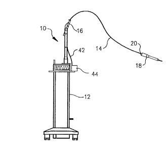
Referring initially to FIGURE 1, shown therein is a laser delivery system 10
generally COlll~liSillg a laser energy generator 12 for generating a beam of laser
energy, which is conrl~ct~l through a flexible hollow wave guide 14 that is supported
on the generator 12 by a support arm 16. A sc~nning hand piece 18 is conntocte~l at
the free end 20 of the hollow wave guide 14. The beam of laser energy 22 exits the
hand piece 18 (shown out of proportion in FIGURE 2 for illustration purposes only).
CA 02234669 1998-04-08
WO 97/16126 PCT~US96/17596
The gen~,la~or 12 is ideally configured to generate pulses of laser energy as described
more fully below. However, the present invention may also be used with continuous
beam laser generators.
Referring next to FIGURE 2, illustrated therein is an enlarged cross-sectional
view of the hand piece 18, which comprises a base 24 threadably connected to a
cylindrical housing 26. The housing has an enlarged motor section 28 that reduces
down to an extended main section 30 that in turn reduces down to an elongated nose
section 32. The base 24 has a centrally disposed cylinflrir~l bore 34. The bore 34
has internal threads 36 that are adapted to receive an externally threaded coupling unit
38. The free end 20 of the hollow wave guide 14 is ~ttzlrhrd to the housing base 24
via the coupling unit 38 such that the laser beam energy is in co~.""~ ir~tion with the
bore 34 in the base 24.
A motor 40 is mounted on the base 24 and has a control cable 42 that extends
through an access opening 46 in the base 24. The control cable 42 is connected to
a control 44 unit on the generator 12. It is to be understood that the motor control
unit 44 may be integral to the hand piece 18 or mounted remotely (as shown) to
minimi7r the weight of the hand piece 18.
The motor 40 is a hollow shaft DC electric or stepper motor that is selected
for its comp~c~tnt?c~ and simplicity and is readily commercially available. However,
any type of motor can be used, such as an air or hydraulic motor or an electric motor
rotating the hollow shaft 48 through a gear, belt, or friction drive arrangement. The
hollow shaft 48 is centrally disposed within the motor 40. A proximal end 50 of the
shaft 48 projects into the bore 34 of the base so that it is in light energy
c~.ll",.l.lir~tion with the generator 12 through the wave guide 14. The hollow shaft
-
CA 02234669 1998-04-08
W O 97/16126 PCTnUS96/17596 -
48 is rotatably mounted in the extended main section 30 of the housing and has a
distal end 52 that projects into the nose section 32.
Mounted within the hollow shaft 48 is a conduit 54 for con~nc tin~: the beam
of laser energy 22. The conduit 54 has a proximal end 56 that extends out the
proxirnal end 50 of the hollow shaft 48 and into the central bore 34 of the housing
base 24. The conduit 54 is preferably a hollow light pipe having the central axis at
its proximal end 56 in ~lignm~nt with the central axis 60 of the hollow shaft 48.
Such light pipes are readily commercially available. However, the distal end 58 is
positioned in the hollow shaft 48 so that it is eccentrically mounted (not aligned) with
respect to the axis 60 of the hollow shaft 48. This is shown more clearly in FIGURE
3.
In order to facilitate ~lignment of the light beam 22 with a target site, an
aiming and tli~t~nee guide in the form of an opening 62 is created in the nose section
32 of the housing 26. Preferably, the guide 62 is formed on opposing sides of the
nose section 32, as shown in FIGURE 3. This enables line of sight aiming and
~lixt~n~e judging by the user when placing the hand piece at or on the target site and
therefore facilitates OL~tilllUlll spacing from the target site. Ideally, the ~ t~n~c
between the distal end 58 of the conduit 54 and the target area will be in the range
of 0 to 3 mm.
As shown in FIGURE 3, as the motor 40 rotates the shaft 48 and conduit 54
in the direction of rotation shown by the arrow 64, the distal end 58 of the conduit
54 traces a circular pattern. If the distal end 58 of the conduit 54 is positioned
eccellllically so that its axis is about one conduit radius from the axis 60, the scanned
pattern will be twice the diameter of the conduit's distal end 58.
CA 02234669 1998-04-08
W O 97/16126 PCTAUS96/17596 -
The cross-sectional configuration of the distal end 58 of the conduit is
preferably tealdlupl)ed shaped, as shown in FIGURE 6C. This shape is substantially
in the fûrm of an isosceles kiangle, and when used with the present invention, the
apex 66 will be mounted at least adjacent to the axis 60 of rotation. When so
mounted and rotated by the motor 40, the conduit 54 will scan the beam 22 of laser
energy in a circular pattern to cover a target area depicted in FIGURE SC.
Similarly, the oval shape depicted in FIGURE 6B will cover a target area
shown in FIGURE SB, and the circular shape shown in FIGURE 6A will cover an
area depicted in FIGURE SA.
In operation, the motor 40 rotates the hollow shaft 48 with the conduit 54
mounted therein. When the conduit 54 rotates, the lon~ clin~l axis of the conduit
54 at the plo~ lal end 56 will be in ~lignment with the axis 60 of the hollow shaft
48. However, the distal end 58 of the conduit 54 will be eccenkic with respect to the
axis 60 and rotate in a circle around the axis 60, as described above.
The distal end 58 of the conduit 54 will rotate at a constant angular rotation
c~, Hertz ("Hz"), with an associated period of rotation T (in seconds). The beam 22
of laser energy from the CO2 generator 12 is ideally emitted in pulses having a
frequency f (in Her~z), with a duration or pulse width of t (in seconds), at a peak
power of P (in watts). It is to be understood, however, that the present invention
may be used with a constant emission of laser energy, as will be readily ascertainable
by one of ol-linaly skill in the art.
The frequency is chosen such that the number of pulses per revolution, N,
provides uniform coverage of the scanned ~ mtoter D (in mm). The required
repetition frequency of laser pulses is:
,
-
CA 02234669 1998-04-08
W O 97/16126 PCT~US96/17596 -
f = (l/T) = c~ x N
To provide "char-free" ablation, the irradiance I should exceed 40 watts/mm2
and t (the pulse duration), should be less than 900 microseconds. Since the distal end
58 of the conduit 54 is constantly moving relative to the target tissue, the area
scanned with the laser energy during each pulse is the swept area As mm2, rather than
the area of the tip A' mm2. This is shown in FIGURE 4, and can be calculated as
follows:
As = At + Ac where Ac = (t x c~ x 7r x D2)/4
so that the irr~ n~e is I = P/As watts/mm2 and
the average power is PaVe = (P x t)/T
The energy per unit area, referred to as the fluence F, must also exceed 40
mJ/mm2. This parameter effectively sets the ,.,i"i",-"" pulse width for t such that:
F = (P x t)/A2
and then tl",n = (F x As)/P
The tissue depth removed per pulse z (in mm), can be estim~tPd by:
Z = (Fth)/Jth
where fluence threshold is F,h - 40 mJ/mm2 and the energy threshold per unit volume
iS J~h = 3000 mJ/mm3.
The depth of tissue removed can then be easily controlled by gating the laser
energy output to occur for an integral number of revolutions of the motor such that:
Ztotal = nrev X Z
~ and the "on" time of the gated laser output burst is:
Tga,ed = nrev/~
where nreV is an integral number.
CA 02234669 1998-04-08
W O 97/16126 PCT~US96/17596
It should be noted that a major advantage of the method of the present
invention is that the laser energy output from the generator 12 need not be
synchronized to the position of the rotating tip. Gating the laser's output time equal
to the period of an integral number of motor revolutions simplifies the control scheme
and allows the sç~nning hand piece 18 to be added to an existing laser system without
mo~lifir~ti- n.
The distal end 58 of the conduit 54 need not have a circular cross-section, as
described above. In fact, there are advantages to using conduits 54 in which the
circular cross-section of the distal end 58 is distorted to an elliptical or Lea.drop
shape. Forming the tip to an elongated shape decreases the cross-sectional area
relative to a circular tip of equal ch~;ull~r~,~cllce, thus increasing the irr~ nre. This
in turn reduces the system power required to meet the threshold of superpulse
irradiance. Elongating the tip also increases the swept area if the ellipse or l~ardl.~
is positioned such that the point of .em~llest ~;Ul V~LLUl~ (the apex 66 shown in FIGURE
6C) is on or substantially ~ çent the axis of rotation 60. An elongated distal end
58 also fills the swept area with less overlap between pulses for more uniform target
tissue ablation.
By modifying the distal end 58 to have dirrel~llL amounts of ecc~,llliciLy and/or
shape, a variety of ~ec~nn~l spot sizes may be easily obtained. Since these conduits
58 are readily available and have a relatively low cost to fabricate, they can be
sterilized for single use to simplify infection control.
Example
The system 10 described above was built and tested based on a Luxar LX-20
SP Novapulse CO2 laser system. The laser energy generator 12 uses a hollow
CA 02234669 1998-04-08
W O 97/16126 PCTrUS96117596 -
flexible wave guide delivery system 14 and can be operated in superpulse modes
capable of delivering gated S0 watt peak pulse trains having pulse widths between 500
and 900 microseconds. The nominal inside diameter of the flexible hollow wave
guide 14 and conduit 54 is 1.0 millimeter, providing an effective spot ~i~m~-ter of 0.8
millimettors.
The distal end 58 of the rotating conduit 54 is deformed from a cross-section
of 0.79 mm2 to a triangular or teardrop shape of 0.48 mm2. The number of pulses
per revolution N was chosen empirically to provide relatively uniform coverage of the
2.5 mm ~ m~ter sc:~nn~cl target area with minim~l overlap between pulses. Laser
pulses are repeated every five milliceconds, allowing a mi~ .,n cooling time
between pulses of:
T~ ,g = T - t = 5ms - 900 microseconds = 4.1 ms, or
4.1 ms/325 microseconds = 13 thermal relaxation time co~ Ls.
The laser pulse frequency is:
f = 1/5 ms = 200 Hz
The motor speed is:
~ = 1/(N x T) = 1/12 x 5 ms) = 16.7 Hz = 1000 RPM
The swept area for t = 500 to 900 microseconds is:
As = 0.48 mm2 + L(0 g ms/(12 x 5 ms)) x (7r x (2.5 mm2)/4)] = 0.53 to 0.56
mm2
The average power can be adjusted by varying t. For t = 500 to 900
microseconds, average power will be:
PaVe = 50 watts x t/5 ms = 5 to 9 watts
The fluence (for t = 500 - 900 microseconds) is:
CA 02234669 1998-04-08
W O 97/16126 PCTAUS96/17S96 -
F = (50 watts x t)/0.56 mm2 = 48 to 80 mJ/mm2
The depth of tissue removed per revolution is:
z = (F - 40 rnJ/mm2)/3000 mJ/mm3 = 3 to 13 micrometers per revolution
By gating the laser signal in integral numbers of revolution times l/ct) (i.e., 60,
120, 180, 240 milli~econds), tissue can be removed to any desired depth. The laser
may also be operated in a non-gated pulsed mode where pulses repeat every five
milli~econds as long as the laser is ~çtll~te~l. Operating in this mode while ~wec;~ g
the handpiece 18 over the target tissue enables the operator or user to ablate even
larger areas more efficiently and ul~rollllly than is possible using a small spot size.
The gating signal can also be modulated on and off while operating in this mode for
lower ablation rates and more precise control. For exampIe, if the laser is modulated
on and off in 60 milli~econd intervals, the range of average power would be reduced
by half, from 5.0 to 9.0 watts down to 2.5 to 4.5 watts.
While a pl~fell~d embodiment of the invention has been illustrated and
described, it is to be understood that various changes may be made therein without
departing from the spirit and scope of the invention. For in.~t~nre, in addition to CO2
laser systems, this invention would also be particularly useful for reducing the size
of an Er:YAG laser system used to ablate hard tissue. Consequently, the invention
is to be limited only by the scope of the claims that follow.