Note: Descriptions are shown in the official language in which they were submitted.
~' ~ CA 02234746 l998-04-l4
63407001.62
Wound Drainage System
The present invention relates to wound drainage
systems.
During surgery and a~terwards, during recovery, it
is o~ten necessary to remove ~luid and wound secretions
~rom the site o~ the wound.
Although previously vacuum pumps were used, it is
now conventional to use vacuum suction ~lasks.
The suction ~lask is evacuated to a high level o~
vacuum, normally around 600 to 700 mm Hg. A Elexible
tube is connected to the ~lask and the other end o~ the
tube is connected to a perf~orated wound drainage tube.
The wound drainage tube, in turn, is introduced into a
hermetically sealed wound cavity. When the line ~rom
the ~lask is opened, the negative pressure prevailing in
the ~lask acts in the wound cavity thus drawing o~
wound secretions down the line into the ~lask.
Once the ~lask is ~ull or the vacuum is no longer
su~icient to draw o~ ~luid, the system may be sa~ely
disposed o~.
Flasks as described above are well-known and such
f~lasks are disclosed in, e.g. EP-A-288679 and Swiss
Patents 596,840 and 584,037. However, as stated above,
these ~lasks are charged with a high vacuum, e.g. around
96 kPa (720 mm Hg) and substantially all o~ that vacuum
Al.~.~EN~:)E~) SHE~
CA 02234746 1998-04-14
acts on the patient.
In certain medical applications, however, such high
vacuums cannot be applied to the patient. This is
particularly the case in e.g. cranial or abdominal
surgery where a much lower vacuum, in the region o~ 13.3
~o 20 kPa (100 to 150 mm Hg) is needed at the patient
end o~ the wound drainage line.
Systems have, therefore, been developed to reduce
the vacuum ~rom a high vacuum suction ~lask. One such
system is disclosed in EP 0 616 815.
In this system, the vacuum in the ~lask is adjusted
to the desired level by ~irst attaching a pressure
measuring device to the neck o~ the ~lask. A valve is
arranged between the ~lask and an adjustment device.
The measuring device and adjustment device control the
opening o~ the valve until the desired pressure is
reached. The adjustment device is then removed and the
wound drainage line is attached to the now low vacuum
suction ~lask.
This system, however, is cumbersome and
ine~icient. It is only used to adjust the vacuum
be~ore use. Normally, however, ~lasks are supplied in a
ready-charged, high vacuum state, ready to be attached
to the wound drainage line. It would there~ore be
desirable to provide a vacuum regulating system which
can be attached to a standard high vacuum ~lask and
which regulates the vacuum at the patient end during use
i~ a low vacuum system is required.
AA,~D~D S~
~ CA 02234746 1998-04-14
. .
WO 99/05319 discloses a wound drainage bottle
which, in one embodiment, has a vacuum reducer to
regulate vacuum levels in order to maintain a constant
vacuum in the bottle throughout the entire ~illing
process.
For reasons o~ economy and convenience, a maximum
vacuum is desirable in the suction ~lask in order to
enable the greatest amount o~ wound secretion to be
sucked into the ~lask be~ore another ~lask is needed.
However, as discussed above, in systems where the vacuum
in the ~lask acts directly on the wound, the suction
level in the wound region is too high ~or some
applications.
Also, it is now common practice to use disposable
wound drainage systems and, there~ore, the cost o~
manu~acture should be kept as low as possible whilst
m~; m~ zing the capacity o~ each ~lask.
One known way o~ stepping down the vacuum ~rom the
~lask to the patient is to use clips on the ~lexible
wound drainage tube to reduce its cross-section. The
system disclosed in DE-B-2356480 uses a ~lexible tube
clip which causes the cross-section o~ the wound
drainage tube to be closed to a certain extent ~or
regulation o~ the internal pressure o~ the vacuum
container. With this system, however, it is not
possible to ensure that outside the sharply constricted
cross-section o~ the ~lexible tube, a constant negative
pressure largely independent o~ the negative pressure
~M~NDFDS~E~
~ ~ CA 02234746 1998-04-14
~7 .. -- , ,,
4 -- r
prevailing in the container can be maintained.
The system disclosed in EP-B-0482029 aims to
provide a ~lexible tube clip with a simple way o~ ~
reducing the cross-section o~ a flexible tube in order
to ~orm a throttle restriction. When used in a tube
connection between a vacuum suction ~lask and a wound
drainage tube, this clip can act independently as a
throttle valve.
This system and other known systems use a bellows-
type arrangement, integrally ~ormed in a cap attached tothe suction ~lask.
In the bellows system, two pivotal arms are
~astened to a bellows arranged on the outside o~ the cap
such that when the bellows are contracted, the arms
close together compressing the cross-section o~ the tube
lying between them. When the tube clip is open, the
same negative pressure prevails in the tube as in the
~lask. The same negative pressure is also ~ormed in the
bellows. This causes the bellows to contract thus
closing the arms o~ the clip which compress the tube.
The resulting reduced negative pressure consequently
acts in the wound drainage tube. With the tube closed,
the ~low ~rom the wound has the e~ect o~ raising the
pressure in the suction tube and bellows. This allows
the bellows and thus the tube to open slightly passing
~luid into the ~lask and again reducing the vacuum.
Thus, in operation, the bellows continually regulate and
maintain a ~airly constant tube opening.
AM~NDED S~tE~
CA 02234746 1998-04-14
Although this system per~orms well, e~ectiveiy and
accurately reducing the vacuum to the desired level it
does have several disadvantages. In particular, the
regulation system is ~ormed as an integral unit with the
S vacuum ~lask. It is thus necessary to purchase the
whole system ~or a low vacuum requirement rather than
converting an already charged high vacuum bottle ~or low
vacuum use i~ desired.
It is desirable, there~ore, to provide a vacuum
regulation system which can be used with existing high
vacuum suction ~lasks to provide accurate continuous
negative pressure regulation during use.
The regulation syste~ should be suitable ~or
converting existing, high vacuum ~lasks ~or low vacuum
applications as required without requiring any
modi~ication to the currently used ~lasks. The ~lask
can thus be used ~or either high or low vacuum
applications.
The present invention thus provides a low vacuum
wound drainage system comprising a high vacuum bottle
having on/o~ means to allow/prevent release o~ the
vacuum ~rom the bottle, and connector means ~or
connection o~ a wound drainage line such that a vacuum
path is provided between the bottle and the wound
drainage line when the on/o~ means is in the on
position; the system ~urther comprising a wound drainage
line adapted to be detachably connected to the vacuum
bottle via the connector means to apply suction at a
AM~NDED S~E~
CA 02234746 1998-04-14
patient end o~ the line; and wherein a regulating valve
is incorporated in the detachable wound drainage line,
said valve acting to continuously regulate the vacuum in
the line, when the line iS attached to the bottle, to
provide a reduced vacuum at the patient end o~ the line;
characterised in that said ~alve comprises a valve spool
slidingly located within a valve body and held by a
spring, and wherein said valve body includes a patient
line port and a high vacuum port, the ~ormer being
connected to a section o~ the wound drainage tube
leading to the patient and ~he latter being connected to
a section o~ the wound drainage tube leading to the high
vacuum bottle; and wherein the spring rate and the
cross-sectional area o~ the valve spool to control the
degree o~ vacuum reduction from the high vacuum source
to the patent line, are selected such that the return
~orce o~ the spring and the pressure in the patient line
acting on the line side o~ the spool equal the external
atmospheric pressure actin~ agaist the other side o~ the
spool when the vacuum in the patient line is the
required low vacuum.
Thus, the same high vacuum ~lask can be used ~or
high vacuum applications by connecting a simple wound
drainage tube, or can be used ~or low vacuum
-applications by connecting a wound drainage tube
incorporating an in-line regulating valve. The ~lask
may be o~ standard const~ction.
The valve comprises a valve spool slidingly located
AI~ID~D ~T
CA 02234746 1998-04-14
within a valve body and held by a spring. Such a system
overcomes disadvantages o~ the prior art bellows
arrangements.
With a bellows device, in order to prevent a high
vacuum surge when the system is switched on, it is
necessary to prime the device by initially compressing
the bellows. This has proved to be awkward in practice
since one hand is needed to s~ueeze the bellows while,
at the same time, the other hand is needed to switch the
on/o~ switch.
The bellows system is also relatively bulky and
cumbersome.
Accordingly viewed ~rom a second aspect the
invention provides a low vacuum wound drainage system
comprising a high vacuum bottle having an outlet port
and connector means and a wound drainage line connected
or adapted to be connected at one end to the outlet port
o~ the bottle via the connector to apply suction to
another, patient end; wherein a regulating valve
continuously regulates the vacuum in the wound drainage
line to provide a reduced vacuum at the patient end, and
wherein the valve comprises a valve body and a valve
spool slidingly located within the valve body, the spool
being spring loaded and arranged ~or reciprocal movement
so as to periodically open and close the valve to
provide said continuous regulation in said line.
Such a system is easier to prime than a bellows
system and is more compact.
hME~.DE~
~ CA 02234746 1998-04-14
The system can be primed by initially pushing the
valve spool inwards, against the ~orce o~ the spring,
be~ore switching the system on~
Whilst the valve body, the ports and the connecting
parts o~ the wound drainage line may be encased in a
housing, part o~ the valve spool may project out ~rom
the housing to allow the valve to be primed be~ore use
by pressing the projecting part. The pre~erred
embodiment, however, incorporates a priming pin which
engages the end o~ the valve spool, at one end. The
other end extends out o~ the valve body so that it can
be pushed in by the user. The pushing ~orce is
transmitted to the valve spool, pushing it in against
the spring ~orce.
The priming pin is pre~erably in the ~orm o~ a key
which engages in the end o~ the valve spool. The pin
pre~erably passes through a slot in the valve housing.
The pin and the slot pre~erably cooperate such that
a~ter insertion into the slot, the pin can be rotated to
a locked position to hold the valve in its primed
position. Be~ore use, the pin is rotated back to its
unlocked position and removed.
In the pre~erred embodiment, a high vacuum port is
provided in the side o~ the valve body such that
movement o~ the spool into the body, against the ~orce
o~ the spring, cuts o~ this port ~rom the inside o~ the
valve body, and hence cuts o~ the path ~rom the high
vacuum source to an outlet port on the patient line side
AMEND~D StlE~
CA 02234746 1998-04-14
o~ the valve.
The spring rate is pre~erably selected to control
the degree o~ vacuum reduction ~rom the high vacuum
source to the patient line, such that the spring return
~orce begins to act against the external atmospheric
pressure acting on the opposite side o~ the spool when
the vacuum in the patient line is at the desired level.
The valve is pre~erably provided in a ~lexible
wound drainage line adapted to be attached to a standard
pre-charged high vacuum ~lask or bottle.
The vacuum is pre~erably reduced ~rom the standard
supplied high vacuum o~ 80 to 93 kPa (600 to 700 mm Hg)
to a low vacuum o~ 13.3 to 26.6 kPa (100 to 200 mm Hg).
Since the in-line regulating valve o~ the present
invention can be used with standard high-vacuum ~lasks
which can, i~ desired, be converted ~or use in low
vacuum applications, the present invention, according to
a ~urther aspect, provides a ~lexible wound drainage
tube having a ~irst section adapted to be connected to a
high vacuum bottle and a second section to be applied to
a wound, said ~irst and second sections being
interconnected via a regulating valve which acts to
continuously provide a lower vacuum in the second
section than that provided in the ~irst section ~rom the
high vacuum bottle.
A pre~erred embodiment o~ the present invention
will now be described, by way o~ example only, with
re~erence to the accompanying drawings.
A~ENDED St~EET
~ ~ CA 02234746 1998-04-14
-- 10 --
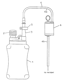
Fig. 1 shows a wound drainage system including an
in-line valve in accordance with the present invention;
Fig. 2 shows the valve in the relaxed condition;
Fig. 3 shows the valve in a partially closed state.
Fig. 4 shows a pre~erred embodiment o~ the valve in
its primed position;
Fig. 5 shows the embodiments o~ Fig. 5 a~ter
removal o~ the priming pin; and
Fig. 6 and 7 show alternative embodiments o~ a
valve according to the present invention.
Figs. 8A, 8B, 9A and 9B show the valve arrangements
with and without vacuum ~or di~erent sealing
arrangements.
The system o~ the present invention controls the
reduction o~ vacuum to the patient to a controlled level
and maintains that level whilst ensuring the cont~;ning
wound drainage vessel ~ills to its capacity.
Fig. 1 shows a wound drainage suction apparatus
incorporating an in-line regulating valve in accordance
with the present invention.
The regulating device is positioned in the line
between the patient and the collection vessel 1 which is
also the high vacuum source. The vacuum source 1 is
pre~erably a disposable, standard, pre-charged vacuum
~lask, supplied charged to a vacuum o~ 96 kPa
(720 mm Xg).
There is a range o~ bottle sizes. A volume scale
may be marked on the bottle to show the ~ill level and
~M~t;lDED S~E~
- CA 02234746 1998-04-14
the bottle is at least partially transparent. Because
disposable systems are pre~erred, the bottle will
normally be made o~ plastic.
The standard bottles are provided with two
openings. A bellows 2 is connected to one o~ these to
provide an indication of the level o~ vacuum remaining
in the flask 1. When the bellows 2 is at its m~i mllm
expansion, this indicates a m;n;mllm negative pressure or
vacuum in the flask 1. A fully contracted bellows
indicates a m~; mnm vacuum.
A tube 3 is connected to the other opening in the
~lask 1. In use, this tube 3 will be connected to a
~lexible wound drainage tube 4. Before use, the tube 3
is closed by a clamp 5 which pinches the tube 3 to
maintain the vacuum in the flask 1.
The bellows 2 and tube 3 may be enclosed in a
plastic cap (not shown). The clamp 5 may also be
enclosed in the cap and operated by an on/o~ switch on
the outside o~ the cap. A port in the cap allows a
wound drainage tube to be connected to the tube 3, in
use.
Vacuum is applied to the patient via a ~lexible
wound drainage tube 4 attached, at one end, to the
vacuum flask 1 via the tube 3. The clamp 5 is opened
causing the negative pressure in the ~lask 1 to exist in
the drainage tube 4 and to be applied to the patient at
the other end o~ the tube 4. This causes ~luid and
wound secretions to be drawn up the wound drainage tube,
CA 02234746 1998-04-14
by suction, into the ~lask 1 which acts as the
collection vessel. When the ~lask 1 is ~ull, it is
thrown away and a new charged vacuum ~lask is used.
As discussed above, it is o~ten not appropriate to
apply the source vacuum o~ 96 kPa (720 mm Hg) directly
to the wound region. It is thus necessary to regulate
the vacuum down to, say, 13.3 kPa (100 mm Hg) at the
patient end o~ the drainage tube 4.
The aim o~ the present invention is to provide a
constant low vacuum output at the patient end for as
long as possible, to m~;m;se e~iciency and to allow
the high vacuum source to be used ~or as long as
possible. In an ideal situation, the vacuum at the
patient end is constant at 13.3 kPa (100 mm Hg) while
the high vacuum decreases ~rom its initial value o~ say
96 kPa (720 mm Hg) to its ~inished, m;n;mllm value when
it needs to be replaced.
The present invention provides this vacuum
regulation by use o~ a valve 6 located in the wound
drainage tube 4. The valve is attached at its two ports
between two sections-4a, 4b o~ the ~lexible wound
drainage tube 4 as shown in Fig. 1.
The construction and operation o~ the valve 6 will
now be described in more detail, with re~erence to Figs
2 to 7.
The valve 6 essentially comprises a valve body 10,
a spool 11, an ori~ice 12 in the spool 11, a spring 13,
seals 14 and vacuum ports 15, 16 to the vacuum source 1
t-~ E~
CA 02234746 1998-04-14
and the patient respectively. The valve parts are all
pre~erably enclosed in a housing 18.
I~ the suction operation is commenced with the
valve 6 in its relaxed position as shown in Fig. 2, a
surge o~ high vacuum in the patient line may result.
This is due to the initial long distance the spool 11
has to travel ~rom the relaxed state o~ Fig. 2 to the
shut-o~ state o~ Fig. 3.
In these circumstances, when the system is switched
on, the patient would initially receive a dosage o~
vacuum above the desired rate. This could have an
adverse e~ect on the patient, particularly in sensitive
areas treated during abdominal or cranial surgery.
To overcome this problem, the valve should be
primed ~or use by initially depressing the spool 11 and
then opening the clamp 5 to release the high vacuum.
The pre~erred embodiment uses a priming pin 17 to
prime the valve be~ore use. The priming pin 17 is in
the ~orm o~ a key having a head 17a, adapted to be
grasped by the user, and an elongate pin body 17b
extending ~rom the head 17a. The ~ree end o~ the pin
body 17b is shaped to engage in a notch or recess in the
end o~ the valve spool 11.
Openings are provided in the valve body 10 and the
valve housing 6, aligned with the notch or recess in the
end o~ the spool 11. The openings correspond to the
diameter o~ the priming pin 17. The pin 17 can thus be
inserted through the openings and engage in the valve
~A~ 'r~l~
CA 02234746 l998-04-l4
- 14 -
spool 11.
In one embodiment, the pin body 17b also has a palr
o~ locking projections extending radially ~rom the body
17b near the pin head 17a. The opening in the valve
housing 18 is provided with corresponding recesses.
When the priming pin 17 is inserted and pushed into the
priming position, the locking projections engage in the
recesses in the opening of the housing. If the pin is
rotated, the projections move out o~ alignment with the
recesses and lock the pin in place in its priming
position.
This arrangement allows the valve to be sold and/or
transported in the primed state. When the valve is to
be used, the nurse or doctor only needs to unlock the
pin by rotating it and then remove it a~ter switching
the device on.
Alternatively, the device may be sold with the
valve in the unprimed, relaxed, state. In that case,
the nurse needs to prime the valve be~ore use by
inserting the pin and pushing it to push the valve spool
inwards against the spring ~orce.
The regulating action o~ the valve 6 during wound
drainage operation is now described.
A~ter priming, the spring 13 will act to return the
spool 11 to the position shown in Fig. 2, with the
ori~ice 12 aligned with the high vacuum port 15. There
is thus a complete path through the valve 6 between the
high vacuum source 1 to the patient line via the valve
I) SffE~
CA 02234746 1998-04-14
ports 15, 16.
When the line to the high vacuum is opened, by
opening the clamp 5, the vacuum level in the valve body
10 and the patient line will rise as the high vacuum
draws/evacuates the valve and the patient line. Since
the atmospheric pressure acting on the spool 11 is
greater than the pressure on the patient side, the spool
11 is drawn into the valve body 10 against the ~orce of
the spring 13.
As the spool 11 continues to move, the ori~ice 12
passes over the seal 14 and is occluded by it thus
~ cutting o~ the high vacuum. The point at which the
ori~ice 12 passes over the seal 14 is the critical point
at which the vacuum that has been allowed to develop in
the patient line is the required low value, e.g. 13.3
kPa (100 mm Hg). This value is determined by the
relationship between the vacuum acting on the end o~ the
cross-sectional area (C.S.A.) o~ the spool 11 and the
spring ~orce o~ the compressed spring 13. Wound
secretions/~luid will then be drawn up the patient line
by this lower regulated vacuum, into the valve body 10.
As the patient line ~ills as the wound is dr~; n~,
the low vacuum level will start to ~all. This lower
vacuum will not be strong enough to hold the spool 11
against the return ~orce o~ the spring 13. Thus, the
spring 13 starts to return the spool 11 out o~ the valve
body 10, allowing the ori~ice 12 to pass back over the
seal 14 to align again with the high vacuum port 15.
AM~DFD~E~
CA 02234746 1998-04-14
- 16 -
The high vacuum will recharge the patient line
until the spool 11 and its ori~ice 12 pass back over the
seal 14 and also allows the material drawn up during the
previous charge o~ the patient line to be passed into
the collection vessel 1.
The cycle thus continues, per~orming constant
regulation o~ the vacuum in the patient line, until the
vessel 1 is ~ull.
It is important that the low vacuum output at the
patient end be as constant and smooth as possible over
time. An important ~actor in providing a continuous
smooth output is the sur~ace resistance between the
valve spool 11 and the seals 14. This resistance must
be m;n;m;sed as much as possible without losing the
sealing e~ect.
In one em~bodiment, O-ring seals are provided on the
valve body 10, shown in Figs. 2 and 3, essentially
corresponding to the two ends o~ the valve spool 11. It
was ~ound, however, that the sur~ace contact, and hence
the resistance, between the valve spool 11 and the seals
14 was too great and the low vacuum output did not
provide a smooth, constant level trace over time, when
measured.
One arrangement considered, shown in Fig. 6,
involved providing seals on the valve spool 11 itsel~,
rather than on the valve body. To ~urther reduce the
sur~ace contact, the O-ring seals were replaced by
rubber ~eather-tip seals. The area o~ contact was thus
hM~N~FD S~tE.ET
- CA 02234746 1998-04-14
reduced to a point at each seal and the resistance was
also reduced.
In a ~urther embodiment shown in Fig. 7, one o~ the
feather-tip seals was replaced by a flexible skirt 19
connected between the valve spool 11 and the valve body
10. The sur~ace contact was thus reduced to a single
point.
Although the use o~ seals on the valve spool 11
improved the smoothness o~ the low vacuum output over
time, it was ~ound that rather than a constant low
vacuum being produced, the low vacuum output actually
decreased over time, as the high vacuum in the ~lask
decreased.
The pre~erred embodiment, shown in Figs. 4 and 5,
thus uses seals on the valve body 10, corresponding to
the ends o~ the sliding valve spool 11.
To reduce resistance, the pre~erred seals are a
unique combination o~ an O-ring seal with a ~eather-tip
seal. Such a seal ensures reliable sealing whilst
having a small sur~ace contact with the spool, at the
point o~ the ~eather-tip. This arrangement has been
~ound to produce a smooth, constant level low vacuum
output over the drainage bottle's ~ill duration.
A ~urther embodiment involves replacing one o~ the
seals with a ~lexible skirt connected between the valve
spool and the valve body.
The seals 14 and spool 11 may be coated to provide
virtually no resistance between the parts to increase
h~ a ~E-~
CA 02234746 l998-04-l4
- 18 -
the accuracy o~ the system.
Whilst the main application ~or this device at
present is ~or removal of wound secretions, another
envisaged application is in autologous blood trans~usion
where a patient's blood is collected during an operation
and subsequent recovery, then ~iltered and returned to
the patient as a trans~usion. This avoids problems in
matching blood to a patient and also reduces the chances
o~ in~ection ~rom donated blood.
In autologous trans~usion systems, blood cannot be
collected under a high vacuum because this causes the
red blood cells to break up.
The present low vacuum system could be used to
collect the blood by providing the above-described valve
in the line between a high vacuum reservoir and a
collection vessel. The pre~erred level o~ vacuum in
this application is around 9.3 to 14.7 kPa (70 to
110 mm Hg).
The present invention thus provides a neat,
sophisticated, precise in-line vacuum regulating device
~or low vacuum medical use.
~~~d'~ r~ E~