Note: Descriptions are shown in the official language in which they were submitted.
CA 02234808 1998-OS-O1
WO 97/16963 PCT/AU96/00693
TITLE
ATTACHABLE TRANSPONDER HOUSING
FIELD OF THE INVENTION
' s This invention relates to an attachable transponder housing
for attachment to a tag assembly which is attachable to animals, and in
particular but not necessarily limited to animals such as ruminants
inclusive of cattle, sheep, goats, deer or camels.
1o BACKGROUND OF THE INVENTION
Identification of ruminants or other animals usually involves
physical identification of distinguishing marks such as hard branding, ear
tagging, ankle tagging and implantable transponders inserted under the
skin.
15 Branding may distress the ruminant and may cause hide
damage resulting in a loss of profit. Further, branding does not identify
individual animals and only identifies the owner of the animal.
Ear tagging techniques generally only provide a visual
representation on the ear tag and is not suitable for automatic
2 o identification of individual ruminants.
A problem with implantabfe transponders is that there is a
possibility that such transponders may migrate in the ruminants either as
a whole or in fragments. Accordingly, due to the rapid production fine in
slaughter houses the transponder or parts thereof may be undetected
2 s resulting in the possibility of the transponder or parts entering the
human
food chain. This is highly undesirable and has been deemed
unacceptable by the Australian Meat and Livestock Corporation.
Another form of identification is that of administering a
' - transponder enclosed in an ingestible capsule into the digestive system of
3 o the ruminant. The ingestible capsule has a specific gravity so that it may
permanently reside for example in the reticulum or rumen. Such capsules
SUBSTTT>;JTE SHEET (Rule 26~
CA 02234808 1998-OS-O1
WO 97/16963 PCT/AU96/00693
2
are disclosed in Patent specifications GB2165723, ZA8303599,
US4262632, W093/05648 and AU63038/94.
Although ingestible capsules provide security they have not
been readily acceptable by, for example, the cattle industry as the
s capsules are not recoverable until slaughter and cannot be administered
to cattle aged three months and under.
A wide variety of forms of tag assemblies are known.
Generally, these include a button that engages a boss formed in a planar
portion of the tag. Visual identification is provided on the planar section by
Zo colour coding or numbering. Some of the prior art tag assemblies include
a housing or chamber in which a transponder may be located. Reference
is made to Alfa-Laval Agriculture International AB application number WO
92/02127 and United States patent number 4694781 in the name of Howe
et al. Neither of these documents describe an attachable transponder
15 housing that is able to be attached to a wide variety of the known animal
identification tags to convert them from visual only to visual and electronic
identification.
It is an aim of this invention to provide an attachable
transponder housing for attachment to a tag assembly which is attachable
2 o to an animal.
It is a further aim of the invention to provide an attachable
transponder housing that converts an existing tag assembly employing
visual identification to also employ electronic identification.
25 SUMMARY OF THE INVENTION
According to one aspect of this invention there is provided
an attachable transponder housing for attachment to a tag assembly, said
attachable transponder housing including:
a body having a chamber containing a transponder therein;
3o and
attachment means associated with the body for pendant
SUBSTITUTE SHEET (Role 26)
CA 02234808 1998-OS-O1
WO 97/16963 PCT/AU96/00693
3
attachment of the attachable transponder housing to the tag assembly;
_ wherein said attachment means comprises two spaced
portions extending from the body and a medial portion joining the spaced
portions such that the spaced portions, medial portion and body form a
' S loop capturing a portion of the tag assembly.
Preferably, said attachment means is integral with said
body.
Suitably, said attachment means is a single strap or looped
member.
1 o The spaced portions are preferably spaced along a length of
the body.
Preferably, the medial portion is of a shape comprising two
laterally extending portions adjacent a respective one of said spaced
portions and an intermediate portion therebetween, said laterally
z5 extending portions being lateral relative to both the longitudinal axis of
said body and the longitudinal axis of said spaced portions.
Suitably, on outer surface area of said body is planar, said
surface area extending along a length of said body.
In preference, the body is formed form a hard plastics
2 o material such as nylon. The hard plastics material is most suitably an
ultraviolet resistant material for prolonged life.
Suitably, the attachment means is flexible or alternatively
rigid.
Preferably, the chamber is of a constant cross sectional
2 5 area.
Suitably, the chamber has a plug inserted in an open end
thereof thereby holding said transponder captive therein. The plug
preferably includes a pressure equalising passage formed therein.
- Alternatively, a pressure equalising passage may be formed in the body.
3 o The pressure equalising passage provides communication between the
chamber and the outside of the body.
SUBSTITUTE SHEET (Rule 26)
CA 02234808 1998-OS-O1
WO 97/16963 PCT/AU96/00693
4
The tag assembly is preferably an ear tag assembly and the
attachable transponder housing preferably attaches to the ear tag
assembly so as to be located between the ear tag assembly and the
animal.
The body of the attachable transponder housing may
suitably be of generally cylindrical shape having a ridge projecting
therefrom.
The attachable transponder housing may further comprise
cushioning means for surrounding the transponder in the chamber.
BRIEF DESCRIPTION OF THE DRAWINGS
In order that this invention may be readily understood and
put into practical effect reference will now be made to a preferred
embodiment illustrated in the accompanying drawings in which:
FIG 1 is a perspective view of an attachable transponder
housing;
FIG 2 is a perspective view of the housing of FIG 1 when
attached to one type of ear tag assembly;
FIG 3 is a perspective view of the housing of FIG 1 when
2 o attached to another type of ear tag assembly;
FIG 4 is a perspective view of a second embodiment of an
attachable transponder housing;
FIG 5 is a perspective view of the housing of FIG 4 when
attached to the type of ear tag assembly of FIG 3; and
FIG 6 is a perspective view of a transponder and cushioning
sheath.
DETAILED DESCRIPTION
Referring to FIG 1 there is illustrated an attachable
3 o transponder housing 1 comprising a body 2 with a chamber 3 of constant
cross-sectional area and extending from body 2 is an integrally formed
SUBSTITIJ'I'E SHEET (Rule 26)
CA 02234808 1998-OS-O1
WO 97/16963 PCT/AU96/00693
attachment means 4.
Contained inside chamber 3 is an electronic identification
transponder 5 which is surrounded by a cushioning means (such as
shown in FIG 6 and described later) which may be a resilient sheath or
' 5 viscous substance. Transponder 5 is held captive in chamber 3 by an
insertable plug 6 having a pressure equalizing slot 7 extending along the
length of plug 6.
Plug 6 may also include a circumferential ridge (not shown)
to assist with retaining the plug 6 in the chamber 3. A corresponding
1 o trough may also be formed on the inside surface of chamber 3.
Attachment means 4 comprises two spaced portions 8
spaced along a longitudinal axis L1 of body 2. Strap 4 also comprises a
medial portion 9 between spaced portions 8. Medial portion 9 is
configured such that it has a shape comprising two laterally extending
portions 10 adjacent a respective one of space portions 8 and an
intermediate portion 11 between portions 10. Further intermediate portion
11 has a circular cross section and spaced portions 8 have longitudinal
axes L2 and L2' which are lateral to longitudinal axis L1 and laterally
extending portions 10 are lateral to both axis L1 and L2, L2'.
2 o Body 2 has an outer surface which has three substantially
flat surface areas extending along the length of body 2 thereby providing
a substantially triangular appearance. The triangular shape provides
strength and resists damage to the body that can occur in normal usage.
Failure of prior art transponder housings due to harsh conditions
associated with livestock has been known and the inventors have found
that strengthening of the body by appropriate shaping can minimise this
problem.
Attachable transponder housing 1 may be formed from any
suitable material, however, the embodiment as illustrated is suitably
3 o formed from injection moulded ultra-violet resistant nylon or plastics
material. After injection moulding attachable transponder housing 1,
SUBSTITUTE SHEET (Rule 26)
CA 02234808 1998-OS-O1
WO 97/16963 PCT/AU96/00693
6
transponder 5 is inserted in chamber 3 and transponder 5 is padded from
shocks by a plastic sheath 24 or a viscous substance. Plug 6 is then
inserted into the open end of chamber 3 in which slot 7 allows for
pressure equalization and therefore ease of insertion. Although the
pressure equalising passage is shown in the plug in the preferred
embodiment, it will be appreciated that a pressure equalising passage
could be formed in the body to achieve the same ease of insertion of the
plug.
Because the transponder 5 can be inserted in the chamber
l0 3 after manufacture the costs associated with failure of the transponder
during the manufacturing process are eliminated. Furthermore, the
transponder can placed in the chamber after the attachable transponder
housing and tag assembly have been attached to the animal.
With reference to FIG 2 there is illustrated attachable
transponder housing 1 attached to an ear tag assembly 12 which
comprises an integral sandwiching member 13 and a male snap fitment
14 at a free end of a shank 15. Ear tag assembly 12 is well-known to
persons skilled in the art and carries visual identification information in
the
form of colour coding or alphanumeric coding. The form of ear tag shown
2 o in FIG 2 cannot carry any form of electronic identification.
In use, attachable transponder housing 1 is positioned as
illustrated before shank 15 pierces through the ear of the animal to be
tagged wherein a planar area 16 of the outer surface of housing 1 faces
the cheek or ear of the animal. Once tagged, housing 1 remains attached
to ear tag assembly 12 by attachment means 4 enclosing a portion of
assembly 12.
If required ear tag assembly 12 may be removed from the
tagged animal and therefore housing 1 may be re-used on another animal
(i.e. if the tagged animal is sold to another person).
3 o A similar arrangement to that shown in FIG 2 can be used
for ankle tagging of animals. The ankle tag is looped through the
SUBSTTTUTE SHEET (Rule ?.~
CA 02234808 1998-OS-O1
WO 97/16963 PCT/AU96/00693
7
attachment means of the attachable transponder housing and then
secured to the animal in the normal way.
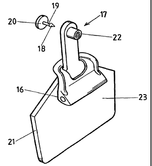
Referring to FIG 3 there is illustrated housing 1 attached to
another form of ear tag assembly 17 which is commonly known to a
' S skilled addressee. Ear tag assembly 17 comprises a button 20 having a
male snap fitment 18 at one end of shank 19 and an ear tag 21 with a
female member 22 for complimentary snap fitment engagement with male
snap fitment 18. In use, housing 1 is positioned as illustrated before
shank 19 pierces through the ear of the animal to be tagged wherein
1 o planar area 16 abuts a non-sandwiching surface 23 of ear tag 21.
Once tagged, housing 1 remains attached to ear tag
assembly 17 by attachment means 4 enclosing a portion of assembly 17.
Further, because of the shape of attachment means 4, surface 16 lies flat
against surface 23 which therefore has aesthetic appeal and reduces
15 movement of housing 1.
A second embodiment of an attachable transponder housing
25 is shown in FIG 4. The attachable transponder housing 25 comprises
a body 26 with a chamber 27 formed therein. As with the previous
embodiment, the chamber 27 houses a transponder 5 in a sheath 24. The
2 o chamber 27 is close by a plug as previously described but not specifically
shown in FIG 4. Extending from body 26 is integrally formed attachment
means 28.
Attachment means 28 comprises two spaced portions 29
spaced along a longitudinal axis of the body 26. The spaced portions 29
25 are joined by a medial portion 30 to form a loop. The medial portion 30
comprises two laterally extending portions 31 extending from the spaced
portions 29 and an intermediate portion 32. Intermediate portion 32 and
laterally extending portions 31 have a substantially square cross-section.
- Laterally extending portions 31 make approximately a ninety degree angle
3 o with spaced portions 29. This allows the attachable transponder housing
25 to sit flat against the ear tag assembly 17 as shown in FIG 5.
SUBSTITUTE SHEET (Rule 26)
CA 02234808 1998-OS-O1
WO 97/16963 1'CT/AU96/00693
8
The body 26 of attachable transponder housing 25 is
generally cylindrical in shape with a projecting ridge 33 formed along one
side. The inventors have found that the projecting ridge 33 provides
additional strength to the housing which is necessary for the purposes
described earlier. The ridge 33 is formed in a side of the body 26 opposite '
to the direction of projection of laterally extending portions 31. This allows
the attachable transponder housing 25 to sit closely and securely against
ear tag 21.
The inventors have found that it is preferable to hang the
1 o attachable transponder housing 25 on the rear of the ear tag 21 so that
visual identification on the front of ear tag 21 is not obscured.
To provide additional strength to the attachable transponder
housing a web 34 is formed between the spaced portions 29. The web 34
also attaches to the body 26. The web 34 provides strength to the
attachment means 28 and minimises the likelihood of failure due to
twisting or stretching.
Although the invention has been described with reference to
preferred embodiments, it is to be understood that the invention is not
limited to the specific embodiments described herein.
SUgg~T~'TE SHEET (Rule 26)