Note: Descriptions are shown in the official language in which they were submitted.
CA 02234842 2001-10-03
-1-
GLIDER CHAIR
Canadian Application No. 2,234,842
BACKGROUND OF THE INVENTION
1. Technical Field
s The present invention relates to a glider chair having a glider mechanism
for
operatively coupling a chair frame to a stationary base, and more particularly
to a glider chair
including a modular chair frame, a base and a glider mechanism which enables
additional
comfort features such as a glide stop assembly, a tilt control assembly, a
reclining seat
assembly and a leg rest assembly to be efficiently incorporated into a glider
chair.
i o 2. Description of Related Art
Comfort chairs which rock or glide are well-known in the art, as are chairs
which
incorporate other features such as reclining seat backs, tiltable chair frames
and extendable
leg rests. In addition, as disclosed in U.S. Patent No. 5,328,235, it is well-
known in the art to
provide a rocking-type chair which includes additional comfort features such
as those set forth
i5 above. However, conspicuously absent from the art is a gliding-type chair
which integrates
additional comfort features in a manner to provide a smoothly operating, quiet
and comfortable
glider chair.
Glider chairs representing the current state of the art typically include a
stationary base
assembly which is laterally reinforced with cross braces to provide the
necessary rigidity to
2 o support the chair frame for proper gliding movement. As such, these chairs
are heavy, costly
and the additional side-to-side bracing can interfere with or unduly limit the
gliding movement
of the chair. Furthermore, these mechanisms may require that the seat be
situated
substantially above the glide mechanism to provide adequate clearance for the
gliding
movement of the chair, thus requiring relatively short glide links to maintain
the proper seating
2 5 height. Accordingly, it would be desirable to provide a glider mechanism
which eliminates
such cross bracing while retaining the rigidity needed for supporting the
chair frame and further
to provide a glider mechanism with extended glide links resulting in a stable,
smooth and
relatively flat gliding motion.
It is also desirable to provide an improved means for selectively locking out
the gliding
3 o movement of the chair. As presently understood, the current state of the
art chairs incorporate
a linkage irtterconnected between the gliding chair frame and the stationary
base which moves
with the chair frame when the chair is gliding and which is fixed when the
chair is locked out.
However, it has been found that these moving lock out linkages generate
unwanted noise,
prematurely wear and add frictional drag which impedes the smooth gliding
movement of the
35 chair. Unwanted noise may also be generated by additional comfort features
whose
CA 02234842 2001-10-03
_2_
Canadian Application No. 2,234,842
components are in motion during gliding movement of the chair. In this regard,
each added
degree of freedom incorporated into a chair frame, e.g., reclining movement of
the seat back,
tilting movement of the chair frame and extension and retraction of the leg
rest, requires an
assembly which may rattle or vibrate due to the gliding movement of the chair
relative to the
s base.
Likewise, the chair frames of these glider chairs are relatively complicated
in design
and are typically assembled utilizing the "chair within a chair" construction
which is known to
be heavy and costly. An improved chair design has recently been developed for
other types of
comfort chairs, such as rockers, recliners, and combinations thereof, which
overcames the
to disadvantages traditionally associated with fabricating, assembling and
upholstering these
chairs. This improved design incorporates an integrated or "knock down"
construction of the
chair enabling unique fabrication and assembly techniques to be utilized which
effectively
result in increased production efficiency and cost savings while concomitantly
producing a high
quality article of furniture. Thus, it would be desirable to also provide a
glider chair having a
15 rigid "box-like" chair frame which adapts the concepts of the integrated or
"knock down" chair
construction into a modular chair frame construction technique for simplifying
assembly
thereof.
SUMMARY OF THE INVENTION
a o In accordance with the principles of the present invention, an improved
glider chair is
disclosed having an improved glider mechanism and whose chair frame readily
lends itself to a
modular construction technique. As a primary object of the present invention,
an improved
glider mechanism for a motion-type chair is provided which suspends a chair
frame above, but
in close proximity to a stationary base. The glider mechanism includes a pair
of front and rear
25 glide links interdisposed between a universal glider bracket and a base
glide assembly for
supporting the chair frame for gliding motion with respect to the base. A
simplified modular
chair frame design is provided which is readily adaptable to the improved
glider mechanism so
as to significantly reduce the chair's overall complexity, weight and cost
without sacrificing the
chair's stiffness and rigidity, thus improving operation and comfort.
3 o It is another object of the present invention to provide a glider chair
which minimizes
the noise and movement generated during gliding movement thereof.
It is a further object of the present invention to provide a glider mechanism
having a
cantilevered base assembly, cambered glide links and utilizing non-precision
bearings which
are laterally preloaded to provide a generally free-swinging glider mechanism.
35 It is a further object of the present invention to provide a glider
mechanism having a
CA 02234842 2001-10-03
-3-
Canadian Application No. 2,234,842
glide lock assembly independent of the glider mechanism for selectively
permitting and
preventing the gliding motion of the chair.
It is still another object of the present invention to provide a glider
mechanism having
forward and rearward limits to prevent gliding movement of the chair frame
with respect to the
s base assembly beyond a predetermined forward and rearward position.
It is yet an additional object of the present invention to provide a glider
chair having a
tilt control assembly interconnected between the chair frame and base and
operably coupled
to an actuation mechanism for causing an angular tilting movement of the chair
frame with
respect to the base assembly.
to It is a further object of the present invention to provide a glider chair
having additional
comfort features such as a swing linkage assembly for reclining the seat back
relative to a seat
member, a seat lock assembly for selectively preventing the reclining motion
of the chair, and
a leg rest assembly positionable between a retracted and protracted position.
is BRIEF DESCRIPTION OF THE DRAWINGS
The various advantages of the present invention will become apparent to one
skilled in
the art by reading the following specification and subjoined claims and
referencing the
following drawings in which:
Figure 1 is a perspective view of a glider chair supported on a swivel base in
a o accordance with a preferred embodiment of the present invention;
Figure 2 is simplified exploded perspective view of a first preferred
embodiment of the
glider chair of the invention illustrating the swivel base and glider assembly
of the present
invention;
Figure 3 is a partial front view of a portion of the glide base assembly
illustrating the
a s cambered glide links of the present invention;
Figure 4 is a side view of the glide link assembly shown in its forwardmost
position;
Figure 5 is a side view of the glide link assembly shown in its rearwardmost
position;
Figure 6 is a perspective view of the drive rod assembly of the actuation
mechanism of
the present invention in a partially exploded and partially assembled
condition;
3 o Figure 7 is a perspective view illustrating the front support shaft,
pantograph linkage, tilt
control assembly and a portion of the swing link assembly of a preferred
embodiment of the
present invention in a partially exploded and partially assembled condition;
Figure 8 is a side view of a glider chair in accordance with a preferred
embodiment of
the present invention illustrating the glide assembly and glide stop assembly
in a disengaged
3s position for permitting gliding movement of the glider chair;
CA 02234842 2001-10-03
-4-
Canadian Application No. 2,234,842
Figure 9 is a side view of the glider chair of Figure 8 illustrating the glide
stop assembly
in an engaged position for preventing gliding motion of the glider chair
relative to the base;
Figure 10 is a side view of a glider chair in accordance with a preferred
embodiment of
the present invention having a tilt control assembly for tilting the chair
frame with respect to the
s base assembly and having a seat lock assembly for selectively locking out
the reclining motion
of the seat back relative to the seat member, the glider chair illustrated in
a non-tilted position
with the seat assembly locked out;
Figure 11 is a side view of the glider chair of Figure 10 illustrating the
glider chair in a
tilted position with the seat assembly unlocked;
io Figure 12 is a perspective view similar to Figure 6 illustrating an
alternative preferred
embodiment of the tilt control assembly of the present invention in a
partially exploded and
partially assembled condition;
Figure 13 is a side view of the glider chair shown in Figure 12 illustrating
the glider
chair in a non-tilted position;
15 Figure 14 is a side view of the glider chair shown in Figure 13
illustrating the glider
chair in a tilted position;
Figure 15 is a simplified exploded perspective view of a second preferred
embodiment
of the invention illustrating a simplified chair frame coupled to a base with
the improved glider
mechanism of the present invention;
2 o Figure 16 is a side elevational view of the glider mechanism shown in
Figure 15,
including the universal glide bracket of the glider mechanism secured to the
seat deck of the
modular chair frame;
Figure 17 is a top view of the universal glide bracket shown in Figure 16; and
Figure 18 is a front view of the glider mechanism shown in Figure 15.
DETAILED DESCRIPTION OF THE PREFERRED EMBODIMENT
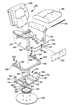
Referring to Figures 1 and 2, a glider chair 20 in accordance with a first
preferred
embodiment of the present invention is shown. The glider chair 20 generally
includes a chair
frame 22 having a pair of side walls 24, a seat member 26, a seat back 28 and
a leg rest
3 o assembly 30 supported on a base 32 having a swivel plate 34 therebetween.
With particular
reference to Figure 2, a pair of side walls 24 are coupled together with a
front support member
36 and a rear support member 46. The front support member 36 includes a pair
of end
brackets 38 secured to an inner wall portion of the side walls 24, a support
shaft 40 which is
suspended from an upper portion of the end brackets, and a lower rail 42
secured to a lower
portion of the end bracket and extending therebetween. A center bracket 44
extends between
CA 02234842 2001-10-03
Canadian Application No. 2,234,842
the support shaft and the lower rail to provide additional stiffness to the
front support member
36. The rear support member 46 is generally C-shaped having a flange 48 formed
on each
end for securing the rear support member to the inner wall portion of the side
walls 24. A drive
rod 50 having a handle 52 disposed on one end is suspended between the side
walls 24 and
s provides means for selectively operating various comfort features functions
of the glide chair.
Further description of a preferred embodiment of the knock-down chair and a
method of
assembly is the subject of U.S. Patent No. 5,475,621 issued July 25, 1995
entitled "'Modular
Rocking Chair and Method", which is commonly owned by the assignee of the
present
invention.
to A chair glide assembly 54 is pivotally coupled to the side walls 24 and
interconnects
the chair frame 22 with the base glide assembly 72 and the base 32. The chair
glide assembly
54 includes a U-shaped tubular subframe 58 having a pair of longitudinal
portions which are
generally parallel to the side walls interconnected by a center portion. A
pair of main pivot
brackets 62 are attached to and extend upwardly from a rear portion of the
tubular subframe
i5 58. A pair of corresponding main pivot mounts 64 are secured to an inner
surface of the side
walls 24 and pivotally connect the chair glide assembly 54 to the chair frame
22. Thus, the
chair frame 22 is supported on and pivotally coupled to the chair glide
assembly 54 for angular
tilting movement therebetween. A universal glide bracket 66 is disposed on an
inboard wall of
the longitudinal portions of the tubular subframe 58 to couple the chair glide
assembly 54 to a
z o base glide assembly 72. An outwardly extending flange 68 formed on the
universal glide
bracket 66 extends underneath the tubular subframe 58 and further supports the
weight of the
glider chair 20 and a seat occupant, as seen in Figure 3. The tubular subframe
58 is attached
to the universal glide bracket 66 by threaded fasteners 70 extending through
the outwardly
extending flange 68 and into the tubular subframe 58 and which are easily
accessible from the
z s bottom of the glider chair 20 during assembly. The universal glide bracket
66 further provides
locations of operably coupling the glide links 92, 108, glide limits 120, 122
and the glide stop
assembly 150 to the chair frame 22 as further described hereafter.
The base glide assembly 72 suspends the chair frame 22 and chair glide
assembly 54
above the base 32 and includes a support frame 74 operably coupled to the base
32 through
3 o the swivel plate 34 for enabling the glider chair 20 to be rotatably
positionable with respect to
the floor. A further description of a preferred embodiment of the swivel plate
is the subject of
U.S. Patent No. 5,435,622 issued July 25, 1995 entitled "Recliner/Rocker
Having Preloaded
Base Assembly" which is commonly owned by the assignee of the present
invention. A pair of
inboard longitudinal support members 76 are secured to the swivel plate 34.
The front and
35 rear lateral support members 78, 80 are disposed on the ends of the inboard
longitudinal
CA 02234842 2001-10-03
-6-
Canadian Application No. 2,234,842
support members 76 and extend laterally with respect to the chair frame 22. A
pair of front
glide uprights 82 and a pair of rear glide uprights 84 are rigidly secured to
and cantilevered
vertically upwardly from the ends of the front and rear lateral support
members 78, 80. A pair
of outboard longitudinal support members 86, 88 are secured to and extend
longitudinally
s befinreen lower portions of the front and rear glide uprights 82, 84. As
presently preferred, the
support frame 74 is constructed of simple angular steel members welded into a
rigid frame
structure with the outboard longitudinal support members 86, 88 providing
additional rigidity to
the support frame.
The chair frame 22 and chair glide assembly 54 are suspended for gliding
movement
io (i.e., generally linear movement along a longitudinal axis and angular
rotation about a lateral
axis) above the base glide assembly 72 on a pair of four-bar linkages 90
operably coupled to
the right and left sides of the base glide assembly 72. The right and left
four-bar linkages 90
are mirror images of one another, accordingly, the right four-bar linkage is
referred to as the
four-bar linkage and further described herein. The four-bar linkage is defined
by the support
is frame 74, the front glide link 92, the universal glide bracket 66 and the
rear glide link 108 which
defines the glider mechanism.
Referring now to Figures 3-5, the front glide link 92 includes an upper
bearing 94
disposed within an upper portion thereof and is operably coupled to the front
glide upright 82
for pivotal motion at the upper pivot pin 96. An upper spacer 102 is disposed
between the
a o upper bearing 94 and the front glide upright 82 to space the front glide
link 92 laterally
outwardly from the support frame 74. Similarly, the lower bearing 98 is
disposed within a lower
portion of the front glide link 92 and operably couples the front glide link
92 to a downwardly
extending tab 104 formed on the universal glide bracket 66 for pivotal motion
on the lower
pivot pin 100. The rear glide link 108 is similar in design and function to
the front glide link 92
z s and includes an upper and lower bearing 110, 114 pivotally coupling the
rear glide link 108 to
the rear glide upright 84 and the universal glide bracket 66 on the upper and
lower pivot pins
116, 118 respectively. An upper spacer 112 is disposed between the upper
bearing 110 and
the rear glide upright 84 to space the rear glide link 108 laterally outwardly
from the support
frame 74.
3 o The front and rear glide links 92, 108 are bent laterally outwardly to
space the chair
glide assembly 54 away from the base glide assembly 72 and provide sufficient
clearance for
unrestricted gliding motion of the chair frame 22 and chair glide assembly 54
with respect to
the base glide assembly 72. As presently preferred, the glide uprights 82, 84
and universal
glide bracket 66 include threaded apertures for receiving upper and tower
pivot pins 96, 100,
3 s 116, 118 having a threaded portion thereon. Furthermore, as seen in Figure
4, the front glide
i
CA 02234842 2002-06-11
_7_
links 92 are interchangeable between the left and right side, thus simplifying
manufacturing and
reducing part inventory requirements and cost.
The upper and lower bearings 94, 1 10, 98, 1 14 in the front and rear glide
link 108 are situated
therein to provide a camber angle between the glide links and the uprights, as
indicated by the angle
a in Figure 3. As presently preferred, a camber angle in the range of
2° - 3° provides sufficient
preloading without causing upper and lower bearings 94, 1 10, 98, 1 14 to
bind. The laterally outwardly
spaced glide links 92, 108 and cantilevered glide upright 82, 84, in addition
to the camber angle
therebetween enables non-precision ball bearings, i.e.. bearings having
tolerance range of
approximately .001 - .010 inches, to be utilized for the upper and lower
bearings 94, 1 10, 98, 1 14.
More specifically, the weight of the chair frame 22 and a seat occupant
therein causes the glide
uprights 82, 84 to deflect at the cantilevered ends. This deflection in
combination with the cambered,
i.e., non-parallel, orientation of the glide links 92, 108 with respect to the
glide uprights 82, 84 induce
a lateral load on the four-bar linkage, i.e., the support frame 74, the front
and rear glide links 92, 108
and the universal glide bracket 66, which preloads the bearings 94, 110, 98,
114 to remove the
clearance and play therefrom and provide smooth gliding movement.
The present invention eliminates the need to provide upper cross braces
extending laterally
between upper portions of the left and right glide uprights 82, 84. The
elimination of these upper cross
braces affords additional clearance for gliding motion of the chair frame and
its associated comfort
feature described hereafter. While Figure 3 illustrates the glide links 92,
108 spaced further outwardly
2 0 at their lower portion, one skilled in the art will readily recognize that
similar advantages could be
achieved by spacing the glide links further outwardly at their upper portion.
Furthermore, other aspects
of the present invention could be practiced in a glider chair having parallel
glide uprights and glide links
or utilizing other pivotal support mechanism known in the art, such as
precision bearings, bushings or
riveted connections, to achieve the desired gliding motion.
The range of motion of the chair glide assembly is set by front and rear glide
limits 120, 122
associated with the universal glide bracket 66. As seen in Figure 4, the chair
glide assembly 54 is
shown in its forwardmost position. In this position the front glide limit 120
which extends inwardly
from the universal glide bracket 66 engages an edge portion of the front glide
link 92 to prevent further
forward movement of the chair glide assembly 54. Similarly, as shown in Figure
5, an edge portion
of the rear glide link engages the rear glide limit 122, extending inwardly
from the universal glide
bracket 66, to limit rearward motion of the chair glide assembly 54. As
presently preferred, the front
and rear glide limits 120, 122 are metal studs extending inwardly from the
universal glide bracket 66
and having a removable
CA 02234842 2001-10-03
_g_
Canadian Application No. 2,234,842
rubber cover 124 for engaging the edge portions of the respective glide links.
It is intended
that the removable rubber cover 124 be replaced after the rubber cover becomes
worn during
the normal course of usage.
With continued reference to Figures 4 and 5, the gliding movement of the
present
s invention is illustrated. In the forwardmost position, the path of the chair
frame as indicated by
the tubular subframe 58 is oriented in an angularly downward fashion such that
the forward
portion of the tubular subframe 58 is lower relative to the base glide
assembly 72 than the
rearward portion of the tubular subframe 58. Thus, the chair frame 22 is
tilted in a forward
position. As the glider chair 20 is urged rearward by a seat occupant, the
tubular subframe 58
to rotates in a counterclockwise position as it translates rearward. Upon
reaching the rear limit
122, the tubular subframe 58 has passed through a parallel condition with
respect to the
support frame 74 and reached a position wherein the rear portion of the
tubular subframe 58 is
situated closer to the base glide assembly 72 than the forward portion of the
tubular subframe
58. Thus, the chair frame 22 is tilted in a rearward position. This type of
combined linear and
15 angular motion is believed to provide a soothing and comfortable motion.
One skilled in the art
will readily appreciate that the precise relationship between the linear and
angular motion
which defines the path of travel for the chair frame may be modified by
varying the geometric
relationship of the front and rear glide uprights, the front and rear glide
links and the universal
glide bracket. The present invention is readily adaptable to a wide range of
chair styles and
a o sizes in that the glider mechanism, which is self-contained within the
chair glide assembly,
base glide assembly, and base, is independent of the chair frame and
additional comfort
features integrated into the glider chair.
In this regard, the glider chair 20 of the present invention may be readily
adapted to
include additional comfort features without significantly adding to the glider
chair's complexity.
2 5 For example, as shown in Figures 8 and 9, a glide stop assembly 150 is
operably coupled to
the drive rod 50 and provides means for selectively permitting or preventing
the gliding motion
of the chair. Similarly, as shown in Figures 10-11 and 13-14, a tilt control
assembly 220 is
operably coupled to the drive rod 50 and interconnected between the tubular
subframe 58 and
the chair frame 22 and provide means for tilting the chair frame 22 relative
to the chair glide
3 o assembly 54. Referring to Figures 6-7 and 10-11, a swing link assembly 190
interconnects the
seat assembly 25 to the side walls 24 and provides means for reclining the
seat back 28
relative to the seat back 28. A seat lock assembly 240 is operably coupled to
the drive rod 50
and provides means for locking out the reclining feature of the glider chair
when in gliding
mode. Also, as best seen in Figures 6 and 7, a leg rest assembly 260 is
operably coupled to
3 5 the drive rod 50 such that it is positionable between a retracted and
extended position. Each
i.
CA 02234842 2002-06-11
_g_
of these features are further described in detail hereafter.
Referring now to Figures 6 and 7, the actuation mechanism 130 is assembled to
include the
drive rod 50 and the front support shaft 40, both of which are spatially
oriented to be precisely located
and suspended from the side walls 24. The upper and lower drive rod supports
134, 136 extend
between the drive rod 50 and the front support shaft 40 to further stabilize
the actuation mechanism
130. A rear portion of the upper drive rod support 134 is coupled to the drive
rod 50 and laterally fixed
thereto. A nylon bushing 138 interdisposed between the upper drive rod support
134 and the drive
rod 50 permits rotational movement of the drive rod 50 therein while a spring
clip 140 fixes the lateral
location. The forward end of the upper drive rod support is secured to the
center bracket 44 of the
front support member 36. Similarly, the lower drive rod support 136 is secured
to the drive rod 50 and
a lower portion of the front support member 36. A rubber bumper 142 is
disposed on the front support
member 36 and extends downwardly to rest on the upper surface of the tubular
subframe 58 when
the chair is in a non-tilted position, as will be further described herein.
With continued reference to Figure 6, a glide stop assembly 150 is provided
which enables
gliding movement of the glider chair to be prevented. The glide stop assembly
150 of the present
invention is independent of the glider mechanism, i.e., does not require an
interconnection between
the chair frame 22 and chair glide assembly 54. Thus, the glider chair 20 of
the present invention
eliminates the extra drag and added wear and tear associated with a lock out
mechanism coupled
between the chair and the base and which moves during gliding movement.
2 0 The glide stop assembly 150 includes left and right glide stop linkages
152 which are mirror
images of one another as shown in an exploded view in the left portion of
Figure 6 and an assembled
view in the right portion of Figure 6. Each right and left glide stop linkage
152 includes a front glide
stop link 152 pivotally connected at an intermediate pivot point to the front
upwardly extending tab
106 formed on the universal glide bracket 66. The front connection link 156
and front drive link 158
operably couple the front glide stop link 152 to the actuation mechanism 130
for pivotally positioning
a cam roller 154, disposed on the end of the front glide stop link 152, into
engagement with the front
glide link 92.
Similarly, the glide stop assembly includes a two-piece rear glide stop link
160 having a rear
glide stop flange link 162 and a rear glide stop extension link 166 pivotally
connected at an
intermediate pivot point to the rear upwardly extending tab 106 formed on the
universal glide bracket
66. The rear glide stop flange link 162 includes a pair of inwardly extending
flanges i 64 which capture
the rear glide stop extension link 166. A bolt or threaded stud 172 extends
from a middle portion of
the rear glide stop flange link 162 for receiving a slot 174 formed in an
intermediate portion of the
extension link 168 to secure the extension link 166 to the flange link 162
while permitting adjustment
of the length of the rear glide stop link 160. A tab 168 is formed on one end
of the extension link 166
and a cam roller 170 is disposed on the opposite end. The rear connection link
176 and rear drive link
178 operably couple the rear glide stop flange link 162 to the actuation
mechanism 130 for pivotally
positioning the cam roller 170 into engagement with the rear glide link 108.
The engagement point
of the glide stop assembly 150 can be adjusted by modifying the length of the
rear glide stop link 160.
CA 02234842 2002-06-11
-10-
Referring now to Figure 8, the glider chair of the present invention is shown
having the glide
stop assembly 150 selectively positioned in an unlocked position. The front
and rear glide stop links
152, 160 are pivotally positioned about the universal glide bracket 66 in a
generally upward direction
out of the way of the path of travel of the chair glide assembly 54. When it
is desired to lock out the
gliding motion of the glider chair 20, the drive rod 50 is rotated in a
counterclockwise direction, as seen
in Figure 9, causing the glide stop assembly 150 to pivotally rotate the front
and rear glide stop links
152, 160 towards a horizontal orientation so that the cam rollers 154, 170
engage the follower
surfaces 180, 182 of the front and rear glide links 92, 108. The follower
surfaces 180, 182 of the
glide stop assembly 150 are machined such that the cam rollers 154, 170 engage
the follower surfaces
180, 182 regardless of the position of the glider chair 20. In this way, the
glide stop assembly 150
can lock out the gliding motion of the glider chair 20 in a smooth and
continuous manner, regardless
of the position of the glider chair. A bevelled flange 184 formed on the
inboard perimeter of the cam
roller further ensures smooth and continuous engagement of the cam rollers
154, 170 with the follower
surfaces 180, 182 during glider lock out. Furthermore, the inwardly extending
flanges 164 formed on
the rear glide stop flange links 162 prevent the rear glide links 108 from
becoming jammed with the
rear glide stop link 160 when the chair frame 22 is in a reward position, thus
ensuring smooth and
continuous engagement of the glide stop assembly irrespective of the position
of the chair frame
relative to the base. In the locked position as shown in Figure 9, the front
and rear glide stop links
152, 160 resist pivotal movement of the front and rear glide links, thus
preventing gliding motion of
2 0 the glider chair.
With continued reference to Figures 7, 8 and 9, the swing link assembly 190
supports the seat
assembly 25 from the side walls 24 such that the seat back 28 may be reclined
with respect to the
seat member 26. As seen in Figure 7, the front portion of the seat assembly is
supported from the side
walls 24 by the support shaft 40. A front slide mount bracket 192 is secured
at the forward portion
of the seat member along a bottom surface thereof. The front slide mount
brackets 192 include a lost
motion slot 194 for guiding and limiting the fore - aft motion of the seat
assembly 25 on the support
shaft 40. A nylon insert 196 is disposed within the lost motion slot 194 to
facilitate sliding movement
between the support shaft 40 and the front slide mount bracket 192. As seen in
Figures 8 and 9, the
rear swing mount bracket 198 is secured to a bottom portion of the seat member
26 for operably
connecting the rear swing link assembly 200 to the seat member 26 and
supporting a rear portion of
the seat assembly 25. The rear swing link 204 is pivotally connected to an
upstanding portion of the
rear swing mount bracket 198. The rear swing mount bracket 198 further
includes downwardly
extending tabs 202 for interconnecting the friction slides 206 between the
rear swing link 204 and the
seat member 26. A retainer 208 having a pair of tabs 210 which extend through
the friction slide 206
properly orient the friction slide 206. A thumb wheel 212 engages a threaded
fastener 214 extending
through the rear swing mount bracket 198, the friction slides 206 and the
retainer 208 to secure the
assembly together. The friction generated by the friction slides 206 can be
adjusted with the thumb
wheel 212 which increases or decreases the load between the friction slide 206
and the downward
extending tab 202. The seat back connector bracket 216 secured to the seat
back 28 engages an
I
CA 02234842 2002-06-11
y
upper portion of the rear swing link 204 for detachably securing the seat back
28 to the swing link
assembly 190. Further description of a preferred swing link assembly is the
subject of U.S. Patent No.
5,222,286 issued January 13, 1992 entitled "Modular Reclining/Tilt Chair and
Method of Making".
Likewise, a metal seat assembly which may be readily incorporated into the
present invention is the
subject of U.S. Patent No. 5,570,930 issued November 5, 1996, entitled
"Recliner Chair Seat
Assembly and Method of Upholstering".
Referring again to Figure 7, a tilt control assembly 220 is interconnected
between the tubular
subframe 58 and the seat member 26 for tilting the chair frame 22 relative to
the base glide assembly
72, i.e. rotating the chair frame about pivot P. In a first preferred
embodiment, the tilt control
assembly 220 is operably coupled to the actuation mechanism 130 and the swing
link assembly 190
for causing the tilting movement. The tilt control assembly 220 includes a
generally straight lift link
222 pivotally connected to a rear portion of the front slide mount bracket 192
at an upper end and
pivotally connected to a lift lever 224 at a lower end. The lift lever 224 is
pivotally connected at a
pivot point 226 intermediate the first and second ends of the lift lever 224
to the front pivot bracket
228 which is secured to the tubular subframe 58. A plurality of pivot
locations are provided on the
lift lever 224 and pivot bracket 228 for adjusting the amount of tilt control
effectuated by the tilt
control assembly 220. The second end of the lift lever 224 is operably coupled
to the drive rod 50
such that rotation of the drive rod 50 causes tilting motion of the chair
frame 22. More specifically,
with reference to Figure 6 the tilt control drive link 232 is secured to the
drive rod 50 for rotation
therewith. The tilt control connection link 234 is generally L-shaped and
extends upwardly and over
the drive
CA 02234842 2001-10-03
-12-
Canadian Application No. 2,234,842
rod to be pivotally connected to the second end of the lift lever 224.
The operation of the tilt control assembly 220 will now be described.
Referring to
Figure 10, the glider chair 20 is illustrated in a non-tilted, non-reclined
position. In this position,
the front portion of the seat assembly 25 is supported by the front support
member 36 which
s rests on a top portion of the tubular subframe 58 and by the main pivot
brackets 62. The
rubber bumper 142 is disposed between the front support member 36 and the
tubular
subframe 58 to eliminate undesirable movement and noise which may be generated
by
various links and pivots associated with the tilt control assembly 220 during
gliding movement.
More specifically, the rubber bumper 142 provides compliance between the front
support
i o member 36 and the tubular subframe 58 such that the weight of a seat
occupant causes the
rubber bumper 142 to compress which in turn slightly laads the pivots and
links within the tilt
control assembly 220 to eliminate unwanted movement therein. As presently
preferred a
rubber bumper having a durometer in the range of 60 - 80 and which compresses
to a height
approximately 50% of the uncompressed height when loaded provides the desired
loading
i5 effects on the tilt control assembly.
Tilting movement is induced as the seat back 28 is reclined with respect to
the seat
member 26. The lift link 222 rotates about its pivotal connection in a
clockwise direction (as
seen in Figure 11 ) to urge the front of the chair frame 22 upward and tilt
chair frame 22 about
pivot point P with respect to the base glide assembly 72 through an angle f3,.
Additional tilting
a o of the chair frame 22 can be achieved by rotation of the drive rod 50 in
the counterclockwise
direction which rotates the lift lever 224 in the counterclockwise direction
about bracket pivot
230 to urge the lift link 222 in an upwardly direction which further tilts the
chair frame 22
relative to the base glide assembly 72 through an angle f32. The total tilting
movement
effectuated by reclining of the seat assembly 25 and actuation of the drive
rod 50 is the sum,
25 f33, of each independent tilting movement, f3, + f32. As presently
preferred, the tilting movement
of the chair frame 22 effectuated by reclining of the seat assembly 25 f3,, is
approximately 4~,
and the tilting movement of the chair frame 22 effectuated by the actuation
mechanism 130,
f32, is approximately 7~. Accordingly, the tilt control assembly 220 enables
the glider chair to
be independently and cumulatively tilted a total of 11 ° in response to
reclining movement of
3o the seat assembly 25 and rotation of the drive rod 50. In the tilted
position, the rubber bumper
142 is rotated out of engagement with the tubular subframe 58 and the weight
of the seat
occupant is supported through the tilt control pivot bracket and the main
pivot bracket.
It is desirable, in certain circumstances, to provide a seat lock assembly 240
for
preventing the reclining motion of the seat back 28 with respect to the seat
member 26 when
3 5 the glider chair 20 is in glide mode -- for example, to maintain proper
balance or to prevent
CA 02234842 2001-10-03
-13-
Canadian Application No. 2,234,842
interference with various assemblies. Referring again to Figure 6, the seat
lock assembly 240
includes a seat lock mount bracket 242 secured to the bottom portion of the
seat member 26
and having a lock pin 244 extending outwardly therefrom. A seat lock stop link
248 is pivotally
connected to a downwardly extending flange 246 of the seat lock mount bracket
242 and has
s an upper end 250 which is positionable to engage the Pock pin 244. The
second end 252 of
the seat lock stop link 248 is operably coupled to the actuation mechanism 130
via the seat
lock drive link 254 and seat lock connection link 258. The seat lock linkage,
i.e., the stop link
248, the connection link 258 and the drive link 256 work in conjunction with
the lock pin 244 to
prevent forward movement of the seat member 26 relative to the actuation
mechanism 130
i o and thus reclining movement of the seat assembly 25, in the following
manner.
Referring to Figure 10, the glider chair 20 is shown with the seat back 28 in
a full
upright position and the seat member 26 in a rearwardmost position. The drive
rod 50 is in its
full clockwise position. In this state, reclining movement of the seat back 28
is prevented by
the seat lock stop link 248 which is pivotally connected to the seat lock
mount bracket 242.
i5 More specifically, pressure applied to the seat back 28 causes the seat
member 26 to slide
forwardly which rotates the seat lock stop link 248 in a clockwise direction.
The upper end 250
of the seat lock stop link 248 engages the lock pin 244 extending from the
seat lock mount
bracket 242 and prevents further movement of the seat member.
To permit reclining movement of the seat back 28 with respect to the seat
member 26,
z o the drive rod 50 is rotated in a counterclockwise direction causing the
seat lock drive link 256
and connection link 258 to rotate the seat IocK stop link 248 in a
counterclockwise direction as
shown in phantom lines in Figure 10. The upper end 250 of the seat lock stop
link 248 is
rotated out of engagement from the lock pin 244 to permit the seat member 26
to be moved
forwardly in conjunction with reclining of the seat back 28. As the seat
assembly 25 is
a s reclined, the pivot associated with the seat lock mount bracket 242 moves
forwardly causing
the seat lock stop link 248 to rotate in a clockwise direction. Further
reclining of the seat back
28 rotates the seat lock stop link 248 about the pivot point until the upper
end 250 of the seat
lock stop link 248 engages the lock pin 244 once again when the seat assembly
25 is in its
fully reclined position, as shown in Figure 11.
3o In an alternate preferred embodiment, tilting movement is provided only
upon selective
manipulation of the actuation mechanism 130. As such, reclining movement of
the seat
assembly 25 no longer effectuates tilting movement of the chair frame 22 with
respect to the
base glide assembly 72. Referring now to Figure 12, the tilt control assembly
220' of the
alternate preferred embodiment is shown. Common elements between the two
preferred
3 s embodiments are given identical reference numerals, while modified
elements are given prime
CA 02234842 2001-10-03
-14-
Canadian Application No. 2,234,842
reference numerals. The main difference between the alternate preferred
embodiments
relates to the geometry of the lift link 222' and its interconnection with the
chair frame 22. As
best seen in Figure 12, the lift link 222' is generally J-shaped having its
upper end pivotally
coupled about the support shaft 40 rather than the front slide mount bracket
192 as in the first
s preferred embodiment. More specifically, the front support shaft 40 is
inserted through a first
end of the lift link 222'. The spring 223' concentrically disposed over the
front support shaft 40
urges the lift link 222' outwardly against the nylon insert 196 of the front
slide mount bracket
192 to prevent the lift link 222' from rattling or otherwise making undesired
noise during gliding
movement of the glider chair 20. The lower end of the lift link 222' is
pivotally connected to the
io lift lever 224' in a manner similar to the first preferred embodiment.
As best seen in Figures 13 and 14, operation of the tilt control assembly of
the
alternate preferred embodiment is shown. Initially, the chair is in a non-
tilted position and the
seat assembly may freely recline without tilting the glider chair. Unlike the
first preferred
embodiment, the seat lock assembly 240 is not provided, thus enabling the seat
back 28 to
is recline, independent of the position of the actuation mechanism 130. Upon
counterclockwise
rotation of the drive rod 50, the tilt control drive link 256' and tilt
control connection link 258'
rotate the lift lever 224' in a counterclockwise direction causing the lift
link 222' to urge the
support shaft 40 upwardly to rotate the glider chair 20 frame about pivot P in
a manner similar
to the first preferred embodiment.
z o Referring now to Figures 7 and 12, a leg rest assembly 260 may be operably
connected to the actuation mechanism 130 for positioning the leg rest assembly
260 between
a retracted position and an extended position. The leg rest assembly 260
includes a leg rest
frame board 262 having an outer surface that is padded and upholstered as
shown in Figures
1 and 2. The frame board 262 is secured to and moved by left and right
pantograph linkages
25 264 which are mirror images of one another. Left and right spring assist
toggle assemblies
266 are provided which work coactively with leg rest pantograph linkages 264.
The toggle
assemblies 266 provide means for securely holding the frame board 262 of the
leg rest
assembly 260 in a fully retracted or fully extended position. The toggle
assemblies 266 are
overcenter mechanism which operate to supply a spring force for biasingly
urging the leg rest
3 o assembly 260 towards its extended and retracted positions. The pantograph
linkage 264 and
toggle assemblies 266 may be similar in function and structure to that shown
in Figure 3 of
U.S. Patent No. 3,096,121, assigned to the common assignee of the present
invention, with
the exception that the pantograph linkages are operably suspended about the
second set of
"fixed" suspension points defined by the support shaft. Alternately, the
pantograph linkages
3s and toggle assemblies may be similar in function and structure to that
shown in U.S. Patent
CA 02234842 2001-10-03
Canadian Application No. 2,234,842
-15-
No. 5,388,886 issued February 14, 1995 entitled "Dual Leg Rest Assembly'"
which is
commonly owned by the assignee of the present invention. Reference may be made
to the
above-identified patents,
Referring now to Figures 15 through 18, a second preferred embodiment of the
s present invention is illustrated. Glider chair 320 is in the form of an
occasional glider chair in
which the seat assembly is fixedly secured to the chair frame, and therefore
does not recline
or tilt relative thereto. Except as discussed below, occasional glider chair
32U and the
components utilized therein are in accordance with glider 20 previously
described as the first
preferred embodiment.
to As best seen in Figure 15, glider chair 320 generally includes chair frame
322 having
left and right side walls 324 (the right side wall not being shown), seat deck
326 and seat back
328 secured together to form a rigid "box-like" chair frame structure. A pair
of universal glide
brackets 330 operably couple chair frame 322 to base glide assembly 332 for
providing gliding
movement between chair frame 322 and base 336. In this regard, base glide
assembly 332,
is swivel plate 334, and base 336 are substantially identical to the base
glide assembly 72,
swivel plate 34 and base 32, respectively, of glider 20 illustrated in Figures
2 through 4 as
discussed above.
With continued reference to Figure 15, the components of chair frame 322 are
assembled by interlocking the individual frame components, seat deck 326
forming the
a o foundational structural element for chair frame 322. More specifically,
seat deck 326 includes
left and right side rails 338, 340 rear cross member 342 and front cross
member 344.
Universal comer bracket 346, a stamped steel bracket having three generally
orthogonal
flanges, is secured to seat deck members 338, 340, 342, 344 in each of the
corners thereof
with suitable fasteners. Front cross member 344 is positioned slightly
vertically above left and
z s right side rails 338, 340 and rear cross member 342 to provide a rearward
inclination to seat
deck 326. Furthermore, front cross member 344 is positioned slightly inboard
of right and left
side rails 338, 340 to form notch 348. In this manner, a very simple, yet
extremely rigid seat
deck 326 having a substantially open interior volume may be fabricated without
the use of glue
or dowel pins, thus greatly reducing the time required for assembly.
3 o Side wall 324 includes inner side frame panel 350 secured to outer side
frame panel
352. Armpost 354 and armrest 356 are secured to a forward edge of inner and
outer side
frame panel 350, 352. Forward panel assembly 358 which includes forward panel
360, front
post 362, universal rail 364 and contoured filler panel 366 is secured to a
front surface of
armpost 354 and the inboard surface of forward panel 360. Seat back 328
includes inner seat
35 back frame 368 supported within outer seat back frame 370.
i
CA 02234842 2002-06-11
-16-
During assembly of chair frame 322, left and right side walls 324 are secured
to corresponding
left and right side rails 338, 340 of seat deck 326 with suitable fasteners
such that a lower, inner edge
of each side wall 324 abuttingly engages the top surface of each side rail
338, 340. Further, an
inboard corner of front post 362 is firmly secured within notch 348 formed
between front cross
member 344 and each side rail 338, 340. Seat back 328 interlocks with and is
secured to a rearwardly
extending portion of side wall 324 and also abuttingly engages a lower back
portion thereof. In this
manner, the components of chair frame 322, i.e., side walls 324, seat deck
326, and seat back 328,
interlock with one another to form rigid "box-like" chair frame 322. While a
fundamental description
of the various components which make up chair frame 322 is disclosed above, a
more detailed
discussion of each of these components, as well as a preferred method of
assembly is set forth in U.S.
Patent No. 5,795,028 entitled "Modular Chair and Method" issued on August 18,
1998 which is
commonly owned by the assignee of the present invention.
Chair frame 322 is operably coupled to base glide assembly 332 by universal
glide bracket 330.
Unlike glider chair 20 of the first preferred embodiment, glider chair 320
does not provide tilting
movement between chair frame 322 and base glide assembly 332. Accordingly,
universal glide bracket
330 is designed to attach directly between chair frame 322 and base glide
assembly 332. Referring
now to Figures 16 through 18, universal glide bracket 330 includes horizontal
surface 372 having a
pair of. horizontal tabs 374 extending outwardly therefrom. Tabs 374 acts as a
horizontal supporting
surface for a bottom edge of side rails 338, 340. Thus, tabs 374 provide a
weigh bearing surface for
2 0 transferring load from chair frame 322 through universal glide bracket 330
to base glide assembly 332,
thereby reducing the shear stress on fasteners 381. Upper vertical flange 376
extends perpendicularly
upwardly from horizontal surface 372, while lower vertical flange 378 extends
perpendicularly
downwardly from horizontal surface 372 and laterally inwardly offset from
upper vertical flange 376.
As best seen in Figure 16, upper vertical flange 376 contains three sets of
three apertures 380, 38-',
380" formed therein which correspondingly align with a set of three bores 341
formed in left and right
side rail 338, 340. Self-tapping, self-countersinking fasteners 381 extend
through bores 341 and tap
through apertures 380 for securing chair frame 322 to universal glide bracket
330. Apertures 380,
380', 380" permit chair frame 322 to be positioned in one of three
forward/rearward location with
respect to universal glide bracket 330, thereby allowing the balance point of
glide chair 320 to be
adjusted according to its styling and balance needs. Similarly, by
accommodating forward/rearward
adjustability in universal glide bracket 330, standard left and right side
rails 338, 340 may be employed
for a variety of chair styles and sizes. Apertures 384 are formed in lower
vertical flange 378 for
receiving lower pivot pins 386 associated with front and rear glide links 390,
392 which operably
couple universal glide bracket 330 with base glide assembly 332 to suspend
chair frame 322 above
base 336 on a pair of four-bar linkages as previously described with respect
to glider chair 20.
As presently preferred, glider chair 320 employs extended front and rear glide
links 390, 392
to provide a smooth and relatively flat gliding motion relative to base glide
assembly 332 and base 336.
More specifically, as best seen in Figure 18, glide uprights 395 extend
upwardly from support frame
396 into the interior volume defined by seat deck 326. Upper pivot pins 388
and an upper portion of
i
CA 02234842 2002-06-11
-17-
front and rear guide links 390, 392 are disposed within the interior volume
defined by seat deck 326.
Lower pivot pins 386 and a lower portion of front and rear glide links are
extended below seat deck
326. As such, chair frame 322 is operably coupled to universal glide bracket
330 at a location
disposed between lower pivot pin 386 and upper pivot pin 388. This allows for
the use of extended
front and rear glide links 390, 392 having a length which extends
approximately between the upper
edge of left side rail 340 and the lower edge of base glide assembly 332 to
achieve a smooth and
relatively flat gliding motion, while maintaining the appropriate positioning
of seat deck 326 to base
336. As presently preferred, front glide links 390 are approximately 6.5 inch
in length as defined
between lower and upper pivot pins 386, 388. Similarly, rear glide links 392
are approximately 5.5
inches in length. Apertures 398 formed in lower vertical flange 378 receive
front and rear rubber-
coated glide stops 400 which define the forward and rearward limits of glider
chair 322 in a manner
similar to that described with respect to glider chair 20.
As best seen in Figure 15, sinuous seat springs 402 extend between front and
rear cross
members 342, 344 of seat deck 326 to provide support for a seat cushion and a
seated occupant.
Referring now to Figures 15 and 18, seat spring support bracket 404 provides
means for vertically
supporting the outermost seat springs to maintain clearance for the range of
motion of front and rear
glide links 390, 392. As best seen in Figure 18, seat spring support bracket
404 is secured to right
side rail 340 and extends upwardly to engage sinuous seat spring 402. More
specifically vertical wall
portion 406 having a pair of apertures formed therethrough receives self-
tapping, self-countersinking
threaded fasteners 408 to secure seat spring support bracket 404 to right side
rail 340. Inwardly
stepped portion 410 appropriately positions horizontal flange portion 412 in a
lateral direction such that
horizontal flange portion 412 engages and supports sinuous seat spring 402. A
threaded fastener 474
having enlarged head portion 416 captures sinuous seat spring 402 for
securement to seat spring
support bracket 404.
As previously discussed, the present invention is designed to utilize non-
precision bearings in
conjunction with glide links 390, 392. A lateral load generated by the weight
of the chair frame 322
and a seated occupant therein is applied to front and rear glide links 390,
392 and reacted through the
non-precision bearings for preloading the bearings to remove the clearance and
play therefrom. More
specifically, the weight of chair frame 322 and an occupant seated therein
causes glide uprights 395
to deflect at the cantilevered ends. This deflection, in combination with the
cambered, i.e., non-
parallel, orientation of front and rear glide links 390, 392 with respect to
the glide uprights 395 induces
a lateral load on the glide mechanism which preloads the upper and lower
bearings thereof to remove
the clearance and play therein. Likewise, front and rear glide links 390, 392
may be laterally loaded
by properly dimensioning seat deck 326 relative to universal glide brackets
330. More specifically, the
distance between left and right side rails 338, 340 of seat deck 326 (as
indicated in Figure 15 as Q1)
is slightly greater than the distance between upper vertical flange portions
376 of right and left
universal glide brackets 330 (indicated as in Figure 15 as 22). Accordingly,
when left or right side rails
338, 340 are secured to universal glide bracket 330, an outwardly directed
lateral load is induced
I
CA 02234842 2002-06-11
-18-
within the front and rear glide links 390, 392, thereby removing the clearance
and play in the bearing
and providing smooth gliding movement.
To further enhance this aspect of the present invention, universal glide
bracket 330 should be
sufficiently stiff to prevent deformation during lateral loading of front and
rear glide links 390, 392,
thereby transferring the lateral loads from chair frame 322 through universal
glide bracket 330 to the
bearings of front and rear glide links 390, 392. In this regard, universal
glide bracket 330 is provided
with a pair of generally vertically extending ribs 394. Ribs 394 extend from
lower vertical flange
portion 378 through horizontal surface 372 to upper vertical flange portion
376. Accordingly ribs 394
prevent relative bending at the intersections between horizontal surface 372
and upper and lower
vertical flange portions 376, 378.
As should be appreciated from the detailed description set forth above, the
glider chair of the
present invention provides an improved glider mechanism which suspends a chair
frame above a base
assembly to permit gliding movement therebetween and which further enables a
modular chair frame
and various comfort features to be readily adapted into the glider chair in a
simple, efficient and
smoothly and quietly operating manner. While the foregoing discussion
discloses and describes various
exemplary embodiments of the present invention, one skilled in the art will
readily recognize from such
discussion, and from the accompanying drawings and claims, that various
changes, modifications and
adaptions can be made therein without departing from the spirit and scope of
the invention as defined
in the following claims.