Language selection

Search

Patent 2234862 Summary

Third-party information liability

Some of the information on this Web page has been provided by external sources. The Government of Canada is not responsible for the accuracy, reliability or currency of the information supplied by external sources. Users wishing to rely upon this information should consult directly with the source of the information. Content provided by external sources is not subject to official languages, privacy and accessibility requirements.

Claims and Abstract availability

Any discrepancies in the text and image of the Claims and Abstract are due to differing posting times. Text of the Claims and Abstract are posted:

  • At the time the application is open to public inspection;
  • At the time of issue of the patent (grant).
(12) Patent: (11) CA 2234862
(54) English Title: BLADE TIP CLEARANCE CONTROL APPARATUS
(54) French Title: DISPOSITIF DE CONTROLE DU JEU D'EXTREMITE POUR OUTILS DE COUPE
Status: Deemed expired
Bibliographic Data
(51) International Patent Classification (IPC):
  • F01D 11/18 (2006.01)
  • F01D 11/24 (2006.01)
(72) Inventors :
  • OWEN, BRIAN CHARLES (United Kingdom)
(73) Owners :
  • ROLLS-ROYCE PLC (United Kingdom)
(71) Applicants :
  • ROLLS-ROYCE PLC (United Kingdom)
(74) Agent: GOWLING WLG (CANADA) LLP
(74) Associate agent:
(45) Issued: 2007-06-19
(22) Filed Date: 1998-04-15
(41) Open to Public Inspection: 1998-10-22
Examination requested: 2003-03-03
Availability of licence: N/A
(25) Language of filing: English

Patent Cooperation Treaty (PCT): No

(30) Application Priority Data:
Application No. Country/Territory Date
08/837,819 United States of America 1997-04-22

Abstracts

English Abstract


A blade tip clearance control apparatus (10) comprises a
plurality of circumferentially arranged spaced wall members
(16) located adjacent the rotor path of a plurality of rotor
blades (14). Each wall member (16) is mounted on a carrier
(18) attached to an annular casing (22) radially outward
thereof. Thermal expansion or contraction of the carrier (18)
causes radial movement of the wall members (16). The wall
members (16) have at least one fluid passage (20) therein. In
operation a flow of fluid passing through the fluid passages
(20) causes either thermal expansion or contraction of the
wall member (16) to different radial positions.


Claims

Note: Claims are shown in the official language in which they were submitted.


6
CLAIMS

1. A blade tip clearance control apparatus comprising a
plurality of circumferentially arranged spaced wall
members located adjacent the rotor path of a plurality of
blades, each wall member has a carrier which extends
radially outward to connect the wall member to an annular
support structure, wherein each carrier has at least one
fluid passage therein, whereby in operation a flow of
fluid passes through the fluid passage to heat and cool
the carrier to control the thermal expansion or
contraction of the carrier and move the wall member to
different radial positions.

2. A blade tip clearance apparatus as claimed in claim
1 wherein each carrier and wall member has a plurality of
fluid passages therein.

3. A blade tip clearance apparatus as claimed in claim
1 or claim 2 wherein the passageways spiral to increase
the residence time of the fluid passing therethrough.

4. A blade tip clearance apparatus as claimed in claim
1 wherein the carrier comprises a plurality of hollow
conduits whereby in operation a flow of fluid passes
through the hollow conduits to control the thermal
expansion or contraction of the conduits to move the wall
member to a different radial position.

5. A blade tip clearance apparatus as claimed in claim
4 wherein the hollow conduits are thermally insulated.


7
6. A blade tip clearance apparatus as claimed in any
one of claims 1 to 5 wherein the carrier has a higher
coefficient of thermal expansion than the annular support
structure.

7. A blade tip clearance control apparatus as claimed
in any one of claims 1 to 6 wherein the wall members are
mounted on the radially inner end of the carrier.

Description

Note: Descriptions are shown in the official language in which they were submitted.


CA 02234862 1998-04-15

BLADE TIP CLEARANCE CONTROL APPARATUS

The present invention relates to a blade tip clearance
control apparatus for use with a gas turbine engine. In
particular the present invention is concerned with providing

a clearance control apparatus for a gas turbine engine to
control the clearance between a casing or static portion of
the engine and the tips of the blades in a rotor.

It is important to keep the clearance between the tips
of the rotating blades and a static portion, such as the
radially inner surface of an annular casing to a minimum. The

clearance is controlled to minimise the leakage of turbine
gases between the casing and the tips of the blades.
Minimising the leakage of the gases improves the engine
efficiency and thereby reduces the specific fuel consumption
of the engine.

During the conventional operating cycle of a gas turbine
engine the blades, and the discs on which they are mounted,
expand due to centrifugal forces acting on them as they
rotate at high speeds and by thermal expansion due to being

heated by the working fluid passing therethrough. The annular
casing also heats up and grows radially outwards resulting in
an increase in the tip clearance between the tips of the
blades and the casing.

The present invention seeks to provide a blade tip
clearance control apparatus which reduces the increase in the
tip clearance between the blades and the casing during engine
operation.

According to the present invention a blade tip clearance
control apparatus comprises a plurality of circumferentially
arranged spaced wall members located adjacent the rotor path

of a plurality of blades, each wall member having a carrier
which extends radially outward to connect the wall member to


CA 02234862 1998-04-15
2

an annular support structure, whereby in operation thermal
expansion or contraction of the carriers causes the wall
members to move to different radial positions.

Preferably the wall members are mounted on the carriers
which are made from a material having a higher coefficient of
thermal expansion than the annular support structure.

The carrier may consist of a plurality of conduits or
have at least one fluid passage therein, whereby in operation
a flow of fluid passing through the conduits or fluid

passages controls the thermal expansion or contraction of the
carrier to move the wall member to a different radial
position.

Preferably each carrier and wall member has a plurality
of fluid passages therein. The fluid passages may be spiral
to increase the residence time of the fluid passing
therethrough and the carrier may be thermally insulated.

The present invention will now be described with
reference to the accompanying drawings in which;

Figure 1 is a cross-sectional view of a tip clearance
control apparatus in accordance with one embodiment of the
present invention.

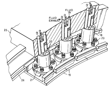
Figure 2 is a pictorial view, partially broken away, of
part of a tip clearance apparatus in accordance with a second
embodiment of the present invention.

Figure 3 is a cross-sectional view of a tip clearance
control apparatus as shown in figure 2.

Figure 4 is a pictorial view of part of a tip clearance
apparatus in accordance with a third embodiment of the
present invention.

Referring to figure 1 a gas passage is defined between
rotor blades 14 and wall members in the form of a plurality
of segments 16. The segments 16 form part of a blade tip


CA 02234862 1998-04-15
3

clearance control apparatus generally indicated at 10. The
function of the apparatus 10 is to control the clearance x
between the tips of the blades 14 and the segments 16 in a
predetermined and controlled manner.

Each segment 16 is mounted on a carrier 18 which is
attached to casing 22. Any radial growth of the casing 22 due
to thermal expansion causes the carriers 18 and the segments
16 to move radially outward. The carrier 18 however is made
from a material which has a higher coefficient of thermal

expansion than the casings 22. The length of the carrier 18
is also such that the change in length of the carrier 18 due
to thermal expansion is greater than the change in the
clearance x caused by the thermal expansion of the casing 22
and the tips of the blades 14. The carrier 18 thus moves the
segments 16 radially inward to reduce the clearance x.

It will be appreciated by one skilled in the art that
the length of the carrier and the coefficient of thermal
expansion of the material from which it is made can be chosen
for a particular application to control the clearance x.

In the second embodiment of the present invention shown
in figures 2 and 3 the carrier 18 is provided with a
plurality of fluid passageways 20. The wall segments 16 are
made separately from the carriers 18 and bolts 23 fasten the
segments 16 to flanges 21 provided at the radially inner end
of the carriers 18.

Isolation rings 24 are also attached to the casing 22.
The isolation rings 24 do not locate the carriers 18 or the
segments 16 unless there is a failure. In the event of a
failure the isolation rings 24 prevent movement of the

carriers 18 and/or the segments 16 radially inwards into the
gas path. Seals (not shown) are inserted into the spaces 26


CA 02234862 1998-04-15
4

between the isolation rings 24 and the segments 16. The seals
prevent the leakage of gas into and out of the gas path.

In operation a flow of fluid is passed through a hole in
the casing 22 and fed down the central passageway 20 in the
carrier 18 to the segment 16. The fluid either impinges upon

the segment 16 or is fed into a cavity (not shown) in the
segment 16. The fluid then exhausts from the carrier 18
through the passageways 20 around the periphery of the
carrier 18 before passing into the main exhaust stream

through a further hole in the casing 22. Although in the
preferred embodiment of the present invention single holes
are used to pass the fluid into and out of the casing 22 it
will be appreciated that multiple holes may be used.

The build clearance between the tips of the blades 14
and the segments 16 is sufficient to accommodate transient
growth of the tips of the rotor blades 14 and the casing 22.
To maintain this clearance during transient conditions a
fluid passes through the passageways 20 to cool the carrier
18 and prevent movement of the segments 16 radially inwards.

Once the tips of the rotor blades 14 and the casing 22
have reached their final steady state growth the fluid in the
passageways 20 has been heated. The heated fluid feeds
through the passageways 20 which cause the carriers 18 and
the corresponding segments 16 to grow radially inwards. The

segments 16 move radially inwards to minimise the clearance
between the blade tips and the segments 16 at steady state
conditions.

In the preferred embodiment of the present a single
fluid, such as air or steam, is used in a closed loop system
whereby the fluid is heated as it passes through the carriers

during operation. However it will be appreciated that
alternatives to the closed loop system described could be


CA 02234862 1998-04-15

used. For example the fluid may be heated externally of the
carriers or separate fluids could be used for cooling and
heating the carriers, means being provided to switch between
the cooling or heating fluids.

5 A tip clearance apparatus 10 in accordance with the
present invention can be tuned to give the required response.
The rate of flow of fluid through the passageways 20, the
fluid used, the length of the passageways 20 or the material
from which the carrier 18 is made can be varied to give the
required clearance control.

It is also envisaged that the passageways 20 could
spiral through the carrier 18 which would increase the
residence time of the fluid flow passing therethrough to
achieve more uniform thermal expansion or contraction of the
carrier 18.

Instead of using a solid carrier 18 with passageways 20
as shown in figures 2 and 3 the carrier could consist of a
plurality of individual conduits 30 through which the fluid
would pass, figure 4. The conduits 30 could be insulated to

prevent thermal growth during transients. The thermal lagging
(not shown) would be such that the conduits 30 would cause
growth of the carrier 18 radially inwards only after the
transient rotor and casing growths have taken place.

In the embodiment shown in figure 4 the wall member 16
is mounted on the carrier 18 by sliding the wall member in
the direction of arrow A over flange 21 attached to the
bottom of the conduits 30.

Representative Drawing
A single figure which represents the drawing illustrating the invention.
Administrative Status

For a clearer understanding of the status of the application/patent presented on this page, the site Disclaimer , as well as the definitions for Patent , Administrative Status , Maintenance Fee  and Payment History  should be consulted.

Administrative Status

Title Date
Forecasted Issue Date 2007-06-19
(22) Filed 1998-04-15
(41) Open to Public Inspection 1998-10-22
Examination Requested 2003-03-03
(45) Issued 2007-06-19
Deemed Expired 2011-04-15

Abandonment History

There is no abandonment history.

Payment History

Fee Type Anniversary Year Due Date Amount Paid Paid Date
Registration of a document - section 124 $100.00 1998-04-15
Application Fee $300.00 1998-04-15
Maintenance Fee - Application - New Act 2 2000-04-17 $100.00 2000-03-24
Maintenance Fee - Application - New Act 3 2001-04-16 $100.00 2001-03-28
Maintenance Fee - Application - New Act 4 2002-04-15 $100.00 2002-03-28
Request for Examination $400.00 2003-03-03
Maintenance Fee - Application - New Act 5 2003-04-15 $150.00 2003-03-14
Maintenance Fee - Application - New Act 6 2004-04-15 $200.00 2004-03-25
Maintenance Fee - Application - New Act 7 2005-04-15 $200.00 2005-03-24
Maintenance Fee - Application - New Act 8 2006-04-17 $200.00 2006-03-20
Final Fee $300.00 2007-02-02
Maintenance Fee - Application - New Act 9 2007-04-16 $200.00 2007-03-21
Maintenance Fee - Patent - New Act 10 2008-04-15 $250.00 2008-03-17
Maintenance Fee - Patent - New Act 11 2009-04-15 $250.00 2009-04-02
Owners on Record

Note: Records showing the ownership history in alphabetical order.

Current Owners on Record
ROLLS-ROYCE PLC
Past Owners on Record
OWEN, BRIAN CHARLES
Past Owners that do not appear in the "Owners on Record" listing will appear in other documentation within the application.
Documents

To view selected files, please enter reCAPTCHA code :


To view images, click a link in the Document Description column. To download the documents, select one or more checkboxes in the first column and then click the "Download Selected in PDF format (Zip Archive)" or the "Download Selected as Single PDF" button.

List of published and non-published patent-specific documents on the CPD .

If you have any difficulty accessing content, you can call the Client Service Centre at 1-866-997-1936 or send them an e-mail at CIPO Client Service Centre.


Document
Description 
Date
(yyyy-mm-dd) 
Number of pages   Size of Image (KB) 
Representative Drawing 1998-11-02 1 5
Cover Page 1998-11-02 1 44
Abstract 1998-04-15 1 19
Description 1998-04-15 5 216
Claims 1998-04-15 2 47
Drawings 1998-04-15 3 75
Claims 2006-03-13 2 42
Representative Drawing 2006-11-21 1 22
Cover Page 2007-05-29 1 53
Assignment 1998-04-15 3 123
Prosecution-Amendment 2003-03-03 1 39
Prosecution-Amendment 2003-04-29 1 26
Fees 2000-03-24 1 30
Prosecution-Amendment 2006-03-13 5 147
Prosecution-Amendment 2005-09-29 2 64
Correspondence 2007-02-02 1 40