Note: Descriptions are shown in the official language in which they were submitted.
CA 02234997 1998-04-16
WO 97/14461 PCT/US96/15787
ANTI-CORING NEEDhE
The present invention relates to
hypodermic needles, and more particularly, to the
type of hypodermic needles that have a rearward end
adapted to establish fluid communication with a
medicament prior to an injection operation.
Hypodermic needles have several
applications. In most such applications the
hypodermic needle has a forward end adapted to
l0 penetrate the skin of an individual, and a rearward
end adapted to communicate with a liquid medicament
source so that the medicament is permitted to travel
from the source, through a central longitudinal bore
in the needle, and into the flesh of the individual.
In many of the applications for hypodermic
needles, it is necessary for the rearward end of the
needle to puncture a seal in order to establish
fluid communication with the medicament source. For
example, one application exists in the field of
automatic injection devices, wherein a liquid
medicament is sealed within a tubular container,
preferably made of glass, having a synthetic rubber
seal closing off a forward end thereof. During an
injection operation, the rearward end of the needle
punctures the seal to establish fluid communication
with the medicament, and a stressed spring assembly
is released so as to cause the forward end of the
needle to project outwardly from the forward end of
automatic injector body and into the flesh of an
individual while such fluid communication is
maintained. A plunger rearwardly confines the
medicament within the container and is driven by the
released spring assembly towards the forward end of
the container and functions to force the medicament
through the needle and into the flesh of the
1
CA 02234997 2005-08-04
individual. Such automatic injection devices are
disclosed, for example, in U.S. Patent Nos.
5,391,151; 5,102,393; and copending U.S. Patent
Application No. Docket 106,-
A problem associated with the
aforementioned arrangements in which the rearward
end of the needle must puncture a rubber or other
type of seal in order to establish fluid
to communication with a medicament is that it is
possible for the rearward end of the needle to core
out or dislodge a small particle from the seal.
This can lead to problems associated with the needle
establishing fluid communication with the
medicament. For example, where a-synthetic rubber
seal is used, a synthetic rubber particle may become
lodged in the needle's rearward end and
significantly reduce the amount of medicament flow
through the needle. While certain types of "anti-
coring" rubber materials, such as natural rubber,
have been used, such materials are not compatible
with as many types of medicaments in comparison with
synthetic rubber.
To obviate the aforementioned problems,
there has been proposed a hypodermic needle in which
a second, lateral opening is provided in the
cylindrical side wall of the needle, towards the
rearward end of the needle. The purpose of
providing a second opening is to enable fluid to
flow freely through the needle even in the event
that the rearward opening is plugged with a rubber
particle. However, this configuration does not
address the potential for a relatively small rubber
particle from entering the rearward end of the
needle and becoming lodged within the bore of the
2
CA 02234997 1998-04-16
WO 97/14461 PCT/US96/15787
needle at, or downstream from, the lateral second
opening, thus impeding fluid flow through the
needle. It also does not address another problem
which may arise when a lateral second opening is
rovided. More s ecificall
p p y, rather than a particle
becoming completely dislodged from the rubber seal,
in some instances the particle may become tethered
to the seal at the point of puncture. In such
instances, it is possible for the tethered particle
l0 to be drawn partially into the second, lateral
opening so as to partially block the longitudinal
passage through the needle and thereby reduce flow
through the needle. It may also be possible for a
dislodged particle to partially enter the second,
lateral opening and thereby reduce flow through the
needle.
It is an object of the present invention
to provide a hypodermic needle that overcomes the
problems noted above. In accordance with the
present invention, there is provided a hypodermic
needle comprising a tubular, elongated, generally
cylindrical wall defining an internal longitudinal
bore extending longitudinally through the
cylindrical wall along a longitudinal axis. The
longitudinal bare has forward and rearward openings.
The cylindrical wall is constructed and arranged to
form a forward pointed end and a rearward pointed
end. The rearward pointed end terminates in an
annular end surface having a rearwardmost point
lying in an imaginary plane disposed perpendicularly
to the longitudinal axis. The annular rearward end
surface defines an imaginary plane inclined with
respect to the imaginary plane perpendicular to the
,E longitudinal axis. The cylindrical wall has a
laterally facing opening spaced from the rearward
3
CA 02234997 1998-04-16
WO 97/14461 PCT/US96/15787
opening of the longitudinal bore, and the
longitudinal bore is restricted at a position
between the rearward opening and the laterally
facing opening.
i
These and other objects, features, and
advantages of the present invention will become
apparent from the following description and the
appended claims, taken in conjunction with the
accompanying drawings.
I0 BRIEF DESCRIPTION OF TiiE DRAWINGS
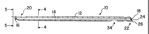
FIGURE 1 is a longitudinal sectional view
of the hypodermic needle according to the principles
of the present invention;
FIGURE 2 is an enlarged longitudinal
sectional view of the rearward portion of the
hypodermic needle in accordance with the principles
of the present invention;
FIGURE 3 is a plan view of the rearward
portion of the hypodermic needle of the present
invention, rotated 90° about the longitudinal axis
with respect to FIGURE 2;
FTGURE 4 is a transverse sectional view
taken through the line 4-4 in FIGURE 1;
FIGURE 5 is a transverse sectional view
taken through the line 5-5 in FIGURE 1;
FIGURE 6 is a longitudinal sectional view
showing the hypodermic needle in accordance with the
present invention, being utilized in conjunction
with a dental cartridge assembly of an automatic
injector assembly in accordance with the principles
of the present invention.
4
CA 02234997 1998-04-16
WO 97114461 PCT/US96/15787
ET~Ih~;D DESCRIPTION OF THE DRAWINGB
Referring now, more particularly, to the
' drawings, there is shown in FIGURE 1 a hypodermic
needle, generally indicated at 10, in accordance
' 5 with the principles of the present invention. The
hypodermic needle comprises a tubular, elongated,
generally cylindrical wall 12 defining an internal
longitudinal bore 14 extending longitudinally
therethrough along a longitudinal axis (indicated at
x in FIGURE 2). The longitudinal bore 14 has a
forward opening 16 and a rearward opening 18.
Preferably, the cylindrical wall 12 is made from
type 304 stainless steel. The cylindrical wall has
a forward pointed end, generally indicated at 20
formed by an angular grind. The cylindrical wall
also has a rearward pointed end, generally indicated
at 22, also formed by an angular grind. The
rearward pointed end 22 is defined by and terminates
in an annular end surface 24. As shown more clearly
in FIGURE 2, the rearward pointed end 22 terminates
in a rearwardmost point 26 lying in an imaginary
plane, indicated at 28, disposed perpendicularly to
the longitudinal axis x. The annular rearward end
surface 24 defines an imaginary plane, indicated at
32, inclined with respect to the imaginary plane 28
perpendicular to the longitudinal axis x.
The cylindrical wall 12 has a laterally
facing opening 34 spaced from the rearward opening
18 of the longitudinal bore 14. As can be
appreciated from the figures, the lateral opening 34
is in longitudinal alignment with the rearwardmost
point 26. The cylindrical wall 12 is crimped or
otherwise extended inwardly into the longitudinal
bore 14 to form a restriction 38
which restricts
,
the longitudinal bore 14 at a position between the
5
CA 02234997 1998-04-16
WO 97J1446i PCT/LJS96/15787
rearward opening 18 and the laterally facing opening
34.
w
As shown in FIGURE 3, the lateral opening
34 is defined by an oblong surface, generally
indicated at 40, defining a beveled edge surrounding
the opening 34. The surface 40 defining the beveled
edge converges as it approaches the longitudinal
axis of the hypodermic needle.
From FIGURES 2 and 3, it can be
appreciated that the more forwardly disposed portion
42 of surface 40 is inclined at a smaller angle with
respect to the longitudinal axis x in comparison
with the rearward portion 44 of surface 40. While
the forwardly disposed surface portion 42 is
I5 substantially flat and forms an angle 8, preferably
in the range of about 28° ~1° with respect to the
longitudinal axis, the rearward portion 44 is
substantially arcuate so as to define an imaginary
circle having a maximum radius R of .0060 inches.
The imaginary plane 32 defined by the
annular end surface 24 forms an angle a with respect
to the imaginary plane 28. Angle a is preferably
about 30° ~1°. The rearwardmost point 26 is
disposed at a distance g from the center of the
restriction 38. Preferably, the distance g is
approximately .030 inches. The rearwardmost point
26 is disposed at a distance h from the closest edge
forming the lateral opening 34. Preferably, the
distance h is approximately .052 ~.002 inches. The
longitudinally rearwardmost and longitudinally
forwardmost portions of the surface 40 forming the
lateral opening 34 are spaced by a distance i.
Preferably, the distance i is approximately .024
~.003 inches. The crimped or inwardly extending
surfaces forming the restriction 38 are separated by
6
CA 02234997 1998-04-16
WO 97/14461 PCT//1JS96/15787
a distance j. Preferably, the distance j is
approximately .005 + .001 to - .002 inches. The
thickness of the cylindrical wall is designated by
reference character t. Preferably the thickness t
is about .0050 + .0010 to -.0015 inches.
Referring to FIGURE 4, which is a
sectional view taken through the line 4-4 in
FTGURE 1, it can be appreciated that the outer
diameter for the major portion of the cylindrical
wall 12 is a dimension k, which is preferably about
.016 - .0165 inches (27 gauge). As can also be
appreciated from FIGURE 4, the cylindrical wail 12
has an inner diameter 1, which is preferably between
about .0075 and .0090 inches.
Referring now to FIGURE 5, which is a
sectional view taken through the line 5-5 in
FIGURE 1, it can be appreciated that surfaces 46
forming the side surfaces leading to the forwardmost
point 48 of the hypodermic needle are inclined by an
2o angle a with respect to an imaginary plane 50
through axis x, as shown. In FIGURE 1, it can be
seen.that the forwardmost point 48 is disposed on
the opposite side of the needle (i.e., out of
longitudinal alignment) with respect to rearwardmost
point 26.
FIGURE 6 is a longitudinal sectional view
of the hypodermic needle of the present invention
shown in cooperation with a dental cartridge
assembly of an automatic injector. The dental
cartridge assembly, generally indicated at60
includes a glass container 62, a forwardly disposed
rubber sealing disc 64, a metallic clamp ring 66,
and a needle hub assembly 68. The clamp ring 66 is
crimped around the forward end of the glass
container 62 so as to enable the rubber sealing disc
7
CA 02234997 1998-04-16
WO 97114461 PCT/US96/15787
64 to form a forward seal for medicament 70
contained within the glass container 62. The needle
hub assembly 68 is fixed to the needle to at a '
position 72 by an epoxy or any conventional fashion.
During an injection operation, the needle hub
assembly 68 is caused to ride rearwardly with
respect to the glass container 62 into the position
shown in FIGURE 6. During this movement of the
needle hub assembly 68, the rearward pointed end 22
l0 of the hypodermic needle 10 is caused to puncture
the rubber sealing disk 64. The specifics of the
injector device of this type can be more fully
appreciated from co-pending U.S. Patent Application
No. 08/280,884, hereby incorporated by reference,
and the aforementioned incorporated U.S. Patent No.
5,202,393 and U.S. Patent Application No. Docket
106.
As shown in FIGURE 6, the puncturing force
of the hypodermic needle 10 has created a tethered
rubber particle 76. Such tethered particle 76 will
ordinarily be formed on a side of the needle
opposite the rearwardmost point 26. The lateral
opening 34 is preferably positioned generally on the
same side of the needle as the rearwardmost point
and most preferably the lateral opening 34 and
rearwardmost point 26 are in longitudinal alignment
with one another so that the tethered particle 76
will not interfere with the opening 34.
In many instances, the particle will be
captured within the rearward opening 18 of the
hypodermic needle, as generally indicated in the
dashed line configuration 80, rather than being _
tethered as with tethered particle 76. Where the
particle 8o becomes lodged in the rearward opening
18, the particle remains at such position, rather
8
CA 02234997 1998-04-16
WO 97/14461 PCTlUS96/15787
than being permitted to float within the medicament
and perhaps find its way to the laterally facing
opening 34, wherein it may block the bore 14 and
severely restrict flow of medicament through the
' 5 needle. The restriction 38 is provided in the
cylindrical wall 12 in order to prevent any further
forward travel of the particle through the bore 14
so that the particle does not become lodged within
the bore at a more downstream position wherein it
may completely prevent fluid flow. With the
rearward opening 18 now substantially blocked by the
particle, the medicament will flow into the bore 14
via the opening 34.
It should also be noted that the oblong
shape of lateral opening 34 minimizes the likelihood
of complete blockage thereof by a dislodged
particle. In addition, the surface 40 and opening
34 are shaped so that they will not cause any
further coring of the seal 64. More specifically,
the arcuate rearward portion 44 (preferably defining
an imaginary circle having a maximum radius of .0060
inches) is shaped such that the portion of the
rubber seal 64 surrounding the puncture hole, and
that slides along the exterior periphery of the
cylindrical wall 12 as the rearward portion of the
needle is moved through the seal 64, will be readily
and smoothly accommodated. In addition, the gently
sloping forward portion 42 (preferably forming an
angle of about 28 1 with respect to the
longitudinal axis x) will gently expand the portions
of seal 64 surrounding the puncture hole as such
portions ride forwardly along the portion 42 as the
needle is further extended into the container,
without any rough or sharp edges of the needle
cutting or biting into the seal 64.
9
CA 02234997 1998-04-16
WO 97/14461 PCT/US96/15787
While the hypodermic needle of the present
invention has been described in conjunction with an
automatic injector, it should be appreciated that
this hypodermic needle has several other
applications in the medical industry, such as '
syringes.
It thus will be seen that the objects of
this invention have been fully and effectively
accomplished. It will be realized, however, that
the foregoing preferred specific embodiment has been
shown and described for the purpose of this
invention and is subject to change without departure
from such principles. Therefore, this invention
includes all modifications encompassed within the
spirit and scope of the following claims.