Language selection

Search

Patent 2235266 Summary

Third-party information liability

Some of the information on this Web page has been provided by external sources. The Government of Canada is not responsible for the accuracy, reliability or currency of the information supplied by external sources. Users wishing to rely upon this information should consult directly with the source of the information. Content provided by external sources is not subject to official languages, privacy and accessibility requirements.

Claims and Abstract availability

Any discrepancies in the text and image of the Claims and Abstract are due to differing posting times. Text of the Claims and Abstract are posted:

  • At the time the application is open to public inspection;
  • At the time of issue of the patent (grant).
(12) Patent: (11) CA 2235266
(54) English Title: TRAY SEALING PLATEN AND SEAL APPARATUS
(54) French Title: SUPPORT PLAT POUR GARNITURE D'ETANCHEITE DE PLATEAU RECIPIENT ET SERTISSEUSE
Status: Term Expired - Post Grant Beyond Limit
Bibliographic Data
(51) International Patent Classification (IPC):
  • A47G 23/06 (2006.01)
  • B23P 19/04 (2006.01)
  • B65B 7/28 (2006.01)
(72) Inventors :
  • DEYOUNG, PERRY R. (United States of America)
(73) Owners :
  • OLIVER PACKAGING AND EQUIPMENT COMPANY
(71) Applicants :
  • OLIVER PACKAGING AND EQUIPMENT COMPANY (United States of America)
(74) Agent: BORDEN LADNER GERVAIS LLP
(74) Associate agent:
(45) Issued: 2005-03-29
(22) Filed Date: 1998-05-19
(41) Open to Public Inspection: 1998-12-02
Examination requested: 1999-05-28
Availability of licence: N/A
Dedicated to the Public: N/A
(25) Language of filing: English

Patent Cooperation Treaty (PCT): No

(30) Application Priority Data:
Application No. Country/Territory Date
08/867,555 (United States of America) 1997-06-02

Abstracts

English Abstract

A peripheral resilient seal, and seal and platen, the platen having a container tray receiving cavity and a peripheral groove around the cavity and receiving the seal. The seal has side ribs deformable upon insertion into the groove, and a shoulder extending beyond the groove to abut the platen.


French Abstract

Joint élastique périphérique, joint et support plat, le support plat comportant une cavité de logement de plateau récipient et une rainure périphérique entourant la cavité et logeant le joint. Le joint comporte des nervures latérales déformables lors de l'insertion dans la rainure, et un épaulement s'étendant au-delà de la rainure pour buter contre le support plat.

Claims

Note: Claims are shown in the official language in which they were submitted.

The invention claimed is:
1. A peripheral seal for apparatus to seal a container flange to a lid,
comprising:
an elongated, resilient, polymeric seal member having sufficient flexibility
to
bend around corners, said seal member having a head portion and a pair of
opposite
side wall portions;
said side wall portions having a plurality of outwardly extending, resilient,
flexible ribs, bendable into gripping relationship with a groove of a width
less than the
width of said seal member; and
said head portion having a lip extending beyond said ribs on at least one side
of
said seal member.
2. The peripheral seal in claim 1 wherein said ribs have outer ends and are
tapered
convergently toward said outer ends.
3. The peripheral seal in claim 2 wherein said seal member has a bottom which
is
arcuately convexly curved.
4. The peripheral seal in claim 1 wherein said seal is of silicone polymer.
5. The peripheral seal in claim 1 wherein said head portion is convexly curved
and
compressible.
6. A platen and peripheral seal apparatus for sealing a container flange to a
lid
comprising:
a platen having a container receiving cavity therein, and having a peripheral
surface around said cavity;
a peripheral groove in said platen surface, adjacent and around said cavity,
and
defining a remaining platen shoulder between said groove and said cavity;
an elongated, resilient, polymeric, peripheral seal member having a bottom
portion and side wall portions in said groove, and having a head portion
protruding
beyond said groove;
said side wall portions having a plurality of outwardly extending, resilient,
flexible ribs bendably deformed into gripping relationship with said groove,
said
-5-

groove having a width less than the width of said seal member including said
ribs
when said ribs are in a relaxed undeformed state.
7. The platen and peripheral seal apparatus in claim 6 wherein said head
portion
has a lip extending outwardly beyond said ribs over said platen shoulder.
8. The platen and peripheral seal apparatus in claim 7 wherein said ribs are
convergently tapered outwardly.
9. The platen and peripheral seal apparatus in claim 6 wherein said bottom
portion
has a configuration matching that of said groove.
10. The platen and peripheral seal apparatus in claim 9 wherein said
configuration
is arcuate.
11. The platen and peripheral seal apparatus in claim 8 wherein said head
portion is
convexly curved.
12. The platen and peripheral seal apparatus in claim 6 wherein said groove
has
a width greater than said seal less said ribs.
-6-

Description

Note: Descriptions are shown in the official language in which they were submitted.


CA 02235266 1999-06-14
TRAY SEALING PLATEN AND SEAL APPARATUS
BACKGROUND OF THE INVENTION
A unique apparatus for sealing lids to tray containers for retaining contents
such
as food has been developed.
S Over a period of use, however, it has been determined that the peripheral
flexible seal of this apparatus, which surrounds the tray receiving cavity and
presses
the container flange against the lid, tends to deform. Periodically it needs
replacement. Presently there are two main techniques for accomplishing this
removal
and replacement. The first technique is to glue a sheet as of silicone polymer
to the
tray holder platen and trim it out, or conceivably die cut it and glue it
down. The
second technique is to take an O-ring rope, cut a peripheral groove in the
platen, and
then glue or press the rope into the groove.
The above first technique involves long assembly time and lead time, with
resulting loss of production time, as well as considerable labor. The second
technique
requires machining time and labor.
Consequently, when the gasket wears or becomes distorted so as to need
replacement, the purchaser of the apparatus is normally not sufficiently
skilled to
accomplish this task. Hence, a service team or person must be brought in, or
the
apparatus shipped back to the manufacturer for repair.
If an O-ring seal were to be employed, the O-ring would not provide the most
desirable choice because an O-ring does not engage and seal the full width of
the tray
flange. Therefore, the peel strength of the lid to the flange is relatively
low so the lid
can come loose with undesirable results. This loss of peel strength is
significant,
especially for paper based trays. If the lid is not sealed at the outer lid
edge, the
overlapping edge tends to become loose and propagate inwardly
SUN1NIARY OF THE INVENTION
This invention provides a novel seal and platen arrangement,
and a novel seal for the apparatus, such that the tray lid sealing apparatus
is capable of
being rapidly and simply repaired by replacement of the sealing member,
without
requiring workmen of special skills, or return of the apparatus to the
manufacturer.
The platen of the invention has a peripheral groove around and closely
adjacent
the tray receiving cavity. A specially configurated, resilient, polymeric
gasket seal is
fitted down into the groove, the gasket seal having laterally projecting
deformable ribs
-1-

CA 02235266 1999-06-14
which become deformed upwardly when the gasket is forcefully inserted down
into the
groove which has a width less than that of the gasket. The gasket seal also
has an
integral lip extending from the head portion to protrude over the shoulder
which is
between the groove and the tray receiving cavity.
These and other features and advantages of the present invention will
be further understood and appreciated by those skilled in the art by reference
to the
following specification, claims and appended drawings.
BRIEF DESCRIPTION OF THE DRAWINGS
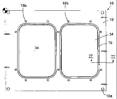
Fig. 1 is a plan view of the tray sealing platen;
Fig. 2 is an end elevational view of the platen;
Fig. 3 is an enlarged, fragmentary, cross sectional view of a portion of the
platen taken on plane III-III of Fig. 1;
Fig. 4 is a cross sectional view of the novel peripheral seal useful for
combining with the platen;
Fig. 5 is a side elevational fragmentary view of the seal in Fig. 4;
Fig. 6 is a top plan view of a representative tray container of the type to be
enclosed with a lid according to this invention;
Fig. 7 is an elevational view of the tray retained by the platen and resting
on
the peripheral seal.
DETAILED DESCRIPTION OF PREFERRED EMBODIMENT
Referring now specifically to the drawings, the tray sealing apparatus is of
the
type described in the Background of the Invention. It includes a platen or
support 18
which can be moved into and out of position for heat sealing of a lid to a
tray as
described. This platen has one or more tray receiving cavities 34, here shown
to be
two in number, for reception of individual tray type containers T (Figs. 6 and
7).
Each such tray normally has an integral peripheral flange F projecting
laterally
outwardly from the tray. This flange is typically in a single plane, and not
only
provides strength to the container but also a surface for sealingly engaging a
lid to
close the container.
Platen 18 has a flat area 18' which surrounds and extends away from cavities
34. The platen is mounted at its four corners 18a. Formed into top surface 18'
of
platen 18 are peripheral grooves 19 (Fig. 3) which respectively extend
completely
around each cavity 34. This groove preferably has a pair of spaced parallel
side walls
-2-

CA 02235266 2004-O1-21
and a concave bottom. A small shoulder 18a remains between cavity 34 and
groove
19.
Fitted into groove 19 is a peripheral elongated gasket seal 21 (Fig. 4). This
gasket has a head 21' , a main body portion 21 ", and a base portion 21 "' .
Seal 21 is
formed of a resilient polymeric material such as silicone rubber. It has
sufficient
flexibility to bend around corners in order to extend around cavity 34. Head
portion
21' has a convexly curved top 21b, the arc of curvature of this surface 21b
being
large. Head portion 21' also has a lip 21a extending laterally on at least one
side of
the head to rest on platen shoulder 18a (Fig. 3) when the seal is installed in
groove 19
as explained hereinafter. The body 21 " of seal 21 has a pair of side wall
portions on
opposite sides, each having a plurality, here three, of outwardly extending,
resilient,
elongated, flexible ribs 21c, each of which is tapered convergently toward the
outer
end thereof. Lip 21a of head 21' preferably projects laterally beyond the
ribs. The
combined width of the seal body, including ribs 21c, is greater than the width
of
groove 19, but the width of seal body 21", less the ribs 21c, is smaller than
the width-
of groove 19. The concave bottom curvature of groove 19 generally corresponds
to
the convex curvilinear configuration of seal bottom portion 21 "' .
Seal member 21 can be forcefully inserted into groove 19 around the entire
tray
cavity until the bottom portions of the groove and seal interfit. The seal is
pressed
down into the cavity until the convex bottom 21 "' engages the bottom of
groove 19,
and lip 21a' rests on shoulder 18a. During this insertion process, resilient
ribs 21c are
in engagement with the side walls of groove 19 to be resiliently deformed
upwardly,
i.e., in the opposite direction as the inserting force. Lip 21a of seal 21
engages the
shoulder 19a between groove 19 and recess 34, while head 21' remains above the
platen surface area 18' .
Seal 21 can be formed as by extrusion. A desired length may be cut to extend
completely around cavity 34 so that the ends abut.
Extending around the groove and seal, but spaced slightly therefrom, are a
plurality of depressible pins in holes 18b formed into the platen for this
purpose, as
disclosed in detail in the previously identified copending application.
In use, after the seal member has been inserted into the groove 19, trays T
are
placed in the cavities 34 so that the peripheral flanges F thereof rest on
seal members
21. The trays can be filled with contents such as food either before placement
in the
-3-

CA 02235266 2004-O1-21
cavities or after insertion. A lid is placed on the tray flange, aligned by
the depressible pins
surrounding it. The platen is then moved beneath an upper platen which is
lowered and
pressed against the lid, the tray flange and seal 21, and heat is applied to
activate an
adhesive between the tray flange and lid. This bonds the lid to the tray
flange, after which
the upper platen is raised, the lower platen 18 is moved from beneath the
upper platen, and
the sealed trays with contents therein are removed from cavities 34.
When seal 21 becomes deformed or otherwise deteriorates after a period of use,
it
can be readily replaced by persons without special skill, by simply pulling
the seal member
out of the groove and inserting a new seal member of the same type.
The above description is considered that of the preferred embodiments) only.
Modifications of the invention will occur to those skilled in the art and to
those who make
or use the invention. Therefore, it is understood that the embodiment shown in
the
drawings and described above is merely for illustrative purposes and not
intended to limit
the scope of the invention, which is defined by the following claims as
interpreted according
to the principles of patent law, including the doctrine of equivalents.
-4-

Representative Drawing
A single figure which represents the drawing illustrating the invention.
Administrative Status

2024-08-01:As part of the Next Generation Patents (NGP) transition, the Canadian Patents Database (CPD) now contains a more detailed Event History, which replicates the Event Log of our new back-office solution.

Please note that "Inactive:" events refers to events no longer in use in our new back-office solution.

For a clearer understanding of the status of the application/patent presented on this page, the site Disclaimer , as well as the definitions for Patent , Event History , Maintenance Fee  and Payment History  should be consulted.

Event History

Description Date
Inactive: Expired (new Act pat) 2018-05-19
Letter Sent 2010-12-06
Inactive: IPC from MCD 2006-03-12
Grant by Issuance 2005-03-29
Inactive: Cover page published 2005-03-28
Inactive: Final fee received 2005-01-14
Pre-grant 2005-01-14
Notice of Allowance is Issued 2004-07-28
Letter Sent 2004-07-28
Notice of Allowance is Issued 2004-07-28
Inactive: Approved for allowance (AFA) 2004-07-12
Amendment Received - Voluntary Amendment 2004-01-21
Inactive: S.30(2) Rules - Examiner requisition 2003-08-19
Letter Sent 1999-06-16
Amendment Received - Voluntary Amendment 1999-06-14
Request for Examination Requirements Determined Compliant 1999-05-28
All Requirements for Examination Determined Compliant 1999-05-28
Request for Examination Received 1999-05-28
Application Published (Open to Public Inspection) 1998-12-02
Inactive: IPC assigned 1998-07-24
Inactive: First IPC assigned 1998-07-24
Classification Modified 1998-07-24
Filing Requirements Determined Compliant 1998-06-29
Inactive: Filing certificate - No RFE (English) 1998-06-29
Inactive: Applicant deleted 1998-06-26
Application Received - Regular National 1998-06-26

Abandonment History

There is no abandonment history.

Maintenance Fee

The last payment was received on 2004-03-26

Note : If the full payment has not been received on or before the date indicated, a further fee may be required which may be one of the following

  • the reinstatement fee;
  • the late payment fee; or
  • additional fee to reverse deemed expiry.

Please refer to the CIPO Patent Fees web page to see all current fee amounts.

Owners on Record

Note: Records showing the ownership history in alphabetical order.

Current Owners on Record
OLIVER PACKAGING AND EQUIPMENT COMPANY
Past Owners on Record
PERRY R. DEYOUNG
Past Owners that do not appear in the "Owners on Record" listing will appear in other documentation within the application.
Documents

To view selected files, please enter reCAPTCHA code :


To view images, click a link in the Document Description column. To download the documents, select one or more checkboxes in the first column and then click the "Download Selected in PDF format (Zip Archive)" or the "Download Selected as Single PDF" button.

List of published and non-published patent-specific documents on the CPD .

If you have any difficulty accessing content, you can call the Client Service Centre at 1-866-997-1936 or send them an e-mail at CIPO Client Service Centre.


Document
Description 
Date
(yyyy-mm-dd) 
Number of pages   Size of Image (KB) 
Representative drawing 1998-12-07 1 7
Description 1998-05-19 4 202
Abstract 1998-05-19 1 11
Claims 1998-05-19 2 62
Drawings 1998-05-19 3 38
Cover Page 1998-12-07 1 34
Description 2004-01-21 4 209
Description 1999-06-14 4 206
Claims 1999-06-14 2 63
Representative drawing 2005-03-01 1 9
Cover Page 2005-03-01 1 32
Courtesy - Certificate of registration (related document(s)) 1998-06-26 1 116
Filing Certificate (English) 1998-06-29 1 163
Acknowledgement of Request for Examination 1999-06-16 1 179
Reminder of maintenance fee due 2000-01-20 1 113
Commissioner's Notice - Application Found Allowable 2004-07-28 1 162
Correspondence 2005-01-14 1 24