Sélection de la langue

Search

Sommaire du brevet 2235266 

Énoncé de désistement de responsabilité concernant l'information provenant de tiers

Une partie des informations de ce site Web a été fournie par des sources externes. Le gouvernement du Canada n'assume aucune responsabilité concernant la précision, l'actualité ou la fiabilité des informations fournies par les sources externes. Les utilisateurs qui désirent employer cette information devraient consulter directement la source des informations. Le contenu fourni par les sources externes n'est pas assujetti aux exigences sur les langues officielles, la protection des renseignements personnels et l'accessibilité.

Disponibilité de l'Abrégé et des Revendications

L'apparition de différences dans le texte et l'image des Revendications et de l'Abrégé dépend du moment auquel le document est publié. Les textes des Revendications et de l'Abrégé sont affichés :

  • lorsque la demande peut être examinée par le public;
  • lorsque le brevet est émis (délivrance).
(12) Brevet: (11) CA 2235266
(54) Titre français: SUPPORT PLAT POUR GARNITURE D'ETANCHEITE DE PLATEAU RECIPIENT ET SERTISSEUSE
(54) Titre anglais: TRAY SEALING PLATEN AND SEAL APPARATUS
Statut: Durée expirée - au-delà du délai suivant l'octroi
Données bibliographiques
(51) Classification internationale des brevets (CIB):
  • A47G 23/06 (2006.01)
  • B23P 19/04 (2006.01)
  • B65B 7/28 (2006.01)
(72) Inventeurs :
  • DEYOUNG, PERRY R. (Etats-Unis d'Amérique)
(73) Titulaires :
  • OLIVER PACKAGING AND EQUIPMENT COMPANY
(71) Demandeurs :
  • OLIVER PACKAGING AND EQUIPMENT COMPANY (Etats-Unis d'Amérique)
(74) Agent: BORDEN LADNER GERVAIS LLP
(74) Co-agent:
(45) Délivré: 2005-03-29
(22) Date de dépôt: 1998-05-19
(41) Mise à la disponibilité du public: 1998-12-02
Requête d'examen: 1999-05-28
Licence disponible: S.O.
Cédé au domaine public: S.O.
(25) Langue des documents déposés: Anglais

Traité de coopération en matière de brevets (PCT): Non

(30) Données de priorité de la demande:
Numéro de la demande Pays / territoire Date
08/867,555 (Etats-Unis d'Amérique) 1997-06-02

Abrégés

Abrégé français

Joint élastique périphérique, joint et support plat, le support plat comportant une cavité de logement de plateau récipient et une rainure périphérique entourant la cavité et logeant le joint. Le joint comporte des nervures latérales déformables lors de l'insertion dans la rainure, et un épaulement s'étendant au-delà de la rainure pour buter contre le support plat.


Abrégé anglais

A peripheral resilient seal, and seal and platen, the platen having a container tray receiving cavity and a peripheral groove around the cavity and receiving the seal. The seal has side ribs deformable upon insertion into the groove, and a shoulder extending beyond the groove to abut the platen.

Revendications

Note : Les revendications sont présentées dans la langue officielle dans laquelle elles ont été soumises.


The invention claimed is:
1. A peripheral seal for apparatus to seal a container flange to a lid,
comprising:
an elongated, resilient, polymeric seal member having sufficient flexibility
to
bend around corners, said seal member having a head portion and a pair of
opposite
side wall portions;
said side wall portions having a plurality of outwardly extending, resilient,
flexible ribs, bendable into gripping relationship with a groove of a width
less than the
width of said seal member; and
said head portion having a lip extending beyond said ribs on at least one side
of
said seal member.
2. The peripheral seal in claim 1 wherein said ribs have outer ends and are
tapered
convergently toward said outer ends.
3. The peripheral seal in claim 2 wherein said seal member has a bottom which
is
arcuately convexly curved.
4. The peripheral seal in claim 1 wherein said seal is of silicone polymer.
5. The peripheral seal in claim 1 wherein said head portion is convexly curved
and
compressible.
6. A platen and peripheral seal apparatus for sealing a container flange to a
lid
comprising:
a platen having a container receiving cavity therein, and having a peripheral
surface around said cavity;
a peripheral groove in said platen surface, adjacent and around said cavity,
and
defining a remaining platen shoulder between said groove and said cavity;
an elongated, resilient, polymeric, peripheral seal member having a bottom
portion and side wall portions in said groove, and having a head portion
protruding
beyond said groove;
said side wall portions having a plurality of outwardly extending, resilient,
flexible ribs bendably deformed into gripping relationship with said groove,
said
-5-

groove having a width less than the width of said seal member including said
ribs
when said ribs are in a relaxed undeformed state.
7. The platen and peripheral seal apparatus in claim 6 wherein said head
portion
has a lip extending outwardly beyond said ribs over said platen shoulder.
8. The platen and peripheral seal apparatus in claim 7 wherein said ribs are
convergently tapered outwardly.
9. The platen and peripheral seal apparatus in claim 6 wherein said bottom
portion
has a configuration matching that of said groove.
10. The platen and peripheral seal apparatus in claim 9 wherein said
configuration
is arcuate.
11. The platen and peripheral seal apparatus in claim 8 wherein said head
portion is
convexly curved.
12. The platen and peripheral seal apparatus in claim 6 wherein said groove
has
a width greater than said seal less said ribs.
-6-

Description

Note : Les descriptions sont présentées dans la langue officielle dans laquelle elles ont été soumises.

CA 02235266 1999-06-14
TRAY SEALING PLATEN AND SEAL APPARATUS
BACKGROUND OF THE INVENTION
A unique apparatus for sealing lids to tray containers for retaining contents
such
as food has been developed.
S Over a period of use, however, it has been determined that the peripheral
flexible seal of this apparatus, which surrounds the tray receiving cavity and
presses
the container flange against the lid, tends to deform. Periodically it needs
replacement. Presently there are two main techniques for accomplishing this
removal
and replacement. The first technique is to glue a sheet as of silicone polymer
to the
tray holder platen and trim it out, or conceivably die cut it and glue it
down. The
second technique is to take an O-ring rope, cut a peripheral groove in the
platen, and
then glue or press the rope into the groove.
The above first technique involves long assembly time and lead time, with
resulting loss of production time, as well as considerable labor. The second
technique
requires machining time and labor.
Consequently, when the gasket wears or becomes distorted so as to need
replacement, the purchaser of the apparatus is normally not sufficiently
skilled to
accomplish this task. Hence, a service team or person must be brought in, or
the
apparatus shipped back to the manufacturer for repair.
If an O-ring seal were to be employed, the O-ring would not provide the most
desirable choice because an O-ring does not engage and seal the full width of
the tray
flange. Therefore, the peel strength of the lid to the flange is relatively
low so the lid
can come loose with undesirable results. This loss of peel strength is
significant,
especially for paper based trays. If the lid is not sealed at the outer lid
edge, the
overlapping edge tends to become loose and propagate inwardly
SUN1NIARY OF THE INVENTION
This invention provides a novel seal and platen arrangement,
and a novel seal for the apparatus, such that the tray lid sealing apparatus
is capable of
being rapidly and simply repaired by replacement of the sealing member,
without
requiring workmen of special skills, or return of the apparatus to the
manufacturer.
The platen of the invention has a peripheral groove around and closely
adjacent
the tray receiving cavity. A specially configurated, resilient, polymeric
gasket seal is
fitted down into the groove, the gasket seal having laterally projecting
deformable ribs
-1-

CA 02235266 1999-06-14
which become deformed upwardly when the gasket is forcefully inserted down
into the
groove which has a width less than that of the gasket. The gasket seal also
has an
integral lip extending from the head portion to protrude over the shoulder
which is
between the groove and the tray receiving cavity.
These and other features and advantages of the present invention will
be further understood and appreciated by those skilled in the art by reference
to the
following specification, claims and appended drawings.
BRIEF DESCRIPTION OF THE DRAWINGS
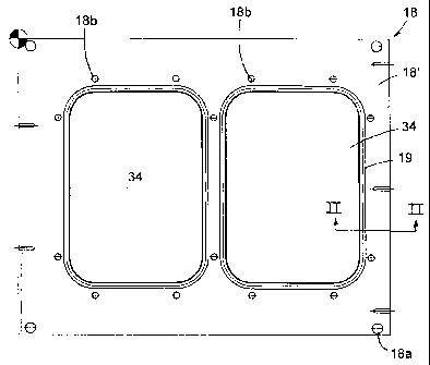
Fig. 1 is a plan view of the tray sealing platen;
Fig. 2 is an end elevational view of the platen;
Fig. 3 is an enlarged, fragmentary, cross sectional view of a portion of the
platen taken on plane III-III of Fig. 1;
Fig. 4 is a cross sectional view of the novel peripheral seal useful for
combining with the platen;
Fig. 5 is a side elevational fragmentary view of the seal in Fig. 4;
Fig. 6 is a top plan view of a representative tray container of the type to be
enclosed with a lid according to this invention;
Fig. 7 is an elevational view of the tray retained by the platen and resting
on
the peripheral seal.
DETAILED DESCRIPTION OF PREFERRED EMBODIMENT
Referring now specifically to the drawings, the tray sealing apparatus is of
the
type described in the Background of the Invention. It includes a platen or
support 18
which can be moved into and out of position for heat sealing of a lid to a
tray as
described. This platen has one or more tray receiving cavities 34, here shown
to be
two in number, for reception of individual tray type containers T (Figs. 6 and
7).
Each such tray normally has an integral peripheral flange F projecting
laterally
outwardly from the tray. This flange is typically in a single plane, and not
only
provides strength to the container but also a surface for sealingly engaging a
lid to
close the container.
Platen 18 has a flat area 18' which surrounds and extends away from cavities
34. The platen is mounted at its four corners 18a. Formed into top surface 18'
of
platen 18 are peripheral grooves 19 (Fig. 3) which respectively extend
completely
around each cavity 34. This groove preferably has a pair of spaced parallel
side walls
-2-

CA 02235266 2004-O1-21
and a concave bottom. A small shoulder 18a remains between cavity 34 and
groove
19.
Fitted into groove 19 is a peripheral elongated gasket seal 21 (Fig. 4). This
gasket has a head 21' , a main body portion 21 ", and a base portion 21 "' .
Seal 21 is
formed of a resilient polymeric material such as silicone rubber. It has
sufficient
flexibility to bend around corners in order to extend around cavity 34. Head
portion
21' has a convexly curved top 21b, the arc of curvature of this surface 21b
being
large. Head portion 21' also has a lip 21a extending laterally on at least one
side of
the head to rest on platen shoulder 18a (Fig. 3) when the seal is installed in
groove 19
as explained hereinafter. The body 21 " of seal 21 has a pair of side wall
portions on
opposite sides, each having a plurality, here three, of outwardly extending,
resilient,
elongated, flexible ribs 21c, each of which is tapered convergently toward the
outer
end thereof. Lip 21a of head 21' preferably projects laterally beyond the
ribs. The
combined width of the seal body, including ribs 21c, is greater than the width
of
groove 19, but the width of seal body 21", less the ribs 21c, is smaller than
the width-
of groove 19. The concave bottom curvature of groove 19 generally corresponds
to
the convex curvilinear configuration of seal bottom portion 21 "' .
Seal member 21 can be forcefully inserted into groove 19 around the entire
tray
cavity until the bottom portions of the groove and seal interfit. The seal is
pressed
down into the cavity until the convex bottom 21 "' engages the bottom of
groove 19,
and lip 21a' rests on shoulder 18a. During this insertion process, resilient
ribs 21c are
in engagement with the side walls of groove 19 to be resiliently deformed
upwardly,
i.e., in the opposite direction as the inserting force. Lip 21a of seal 21
engages the
shoulder 19a between groove 19 and recess 34, while head 21' remains above the
platen surface area 18' .
Seal 21 can be formed as by extrusion. A desired length may be cut to extend
completely around cavity 34 so that the ends abut.
Extending around the groove and seal, but spaced slightly therefrom, are a
plurality of depressible pins in holes 18b formed into the platen for this
purpose, as
disclosed in detail in the previously identified copending application.
In use, after the seal member has been inserted into the groove 19, trays T
are
placed in the cavities 34 so that the peripheral flanges F thereof rest on
seal members
21. The trays can be filled with contents such as food either before placement
in the
-3-

CA 02235266 2004-O1-21
cavities or after insertion. A lid is placed on the tray flange, aligned by
the depressible pins
surrounding it. The platen is then moved beneath an upper platen which is
lowered and
pressed against the lid, the tray flange and seal 21, and heat is applied to
activate an
adhesive between the tray flange and lid. This bonds the lid to the tray
flange, after which
the upper platen is raised, the lower platen 18 is moved from beneath the
upper platen, and
the sealed trays with contents therein are removed from cavities 34.
When seal 21 becomes deformed or otherwise deteriorates after a period of use,
it
can be readily replaced by persons without special skill, by simply pulling
the seal member
out of the groove and inserting a new seal member of the same type.
The above description is considered that of the preferred embodiments) only.
Modifications of the invention will occur to those skilled in the art and to
those who make
or use the invention. Therefore, it is understood that the embodiment shown in
the
drawings and described above is merely for illustrative purposes and not
intended to limit
the scope of the invention, which is defined by the following claims as
interpreted according
to the principles of patent law, including the doctrine of equivalents.
-4-

Dessin représentatif
Une figure unique qui représente un dessin illustrant l'invention.
États administratifs

2024-08-01 : Dans le cadre de la transition vers les Brevets de nouvelle génération (BNG), la base de données sur les brevets canadiens (BDBC) contient désormais un Historique d'événement plus détaillé, qui reproduit le Journal des événements de notre nouvelle solution interne.

Veuillez noter que les événements débutant par « Inactive : » se réfèrent à des événements qui ne sont plus utilisés dans notre nouvelle solution interne.

Pour une meilleure compréhension de l'état de la demande ou brevet qui figure sur cette page, la rubrique Mise en garde , et les descriptions de Brevet , Historique d'événement , Taxes périodiques et Historique des paiements devraient être consultées.

Historique d'événement

Description Date
Inactive : Périmé (brevet - nouvelle loi) 2018-05-19
Lettre envoyée 2010-12-06
Inactive : CIB de MCD 2006-03-12
Accordé par délivrance 2005-03-29
Inactive : Page couverture publiée 2005-03-28
Inactive : Taxe finale reçue 2005-01-14
Préoctroi 2005-01-14
Un avis d'acceptation est envoyé 2004-07-28
Lettre envoyée 2004-07-28
Un avis d'acceptation est envoyé 2004-07-28
Inactive : Approuvée aux fins d'acceptation (AFA) 2004-07-12
Modification reçue - modification volontaire 2004-01-21
Inactive : Dem. de l'examinateur par.30(2) Règles 2003-08-19
Lettre envoyée 1999-06-16
Modification reçue - modification volontaire 1999-06-14
Exigences pour une requête d'examen - jugée conforme 1999-05-28
Toutes les exigences pour l'examen - jugée conforme 1999-05-28
Requête d'examen reçue 1999-05-28
Demande publiée (accessible au public) 1998-12-02
Inactive : CIB attribuée 1998-07-24
Inactive : CIB en 1re position 1998-07-24
Symbole de classement modifié 1998-07-24
Exigences de dépôt - jugé conforme 1998-06-29
Inactive : Certificat de dépôt - Sans RE (Anglais) 1998-06-29
Inactive : Demandeur supprimé 1998-06-26
Demande reçue - nationale ordinaire 1998-06-26

Historique d'abandonnement

Il n'y a pas d'historique d'abandonnement

Taxes périodiques

Le dernier paiement a été reçu le 2004-03-26

Avis : Si le paiement en totalité n'a pas été reçu au plus tard à la date indiquée, une taxe supplémentaire peut être imposée, soit une des taxes suivantes :

  • taxe de rétablissement ;
  • taxe pour paiement en souffrance ; ou
  • taxe additionnelle pour le renversement d'une péremption réputée.

Veuillez vous référer à la page web des taxes sur les brevets de l'OPIC pour voir tous les montants actuels des taxes.

Titulaires au dossier

Les titulaires actuels et antérieures au dossier sont affichés en ordre alphabétique.

Titulaires actuels au dossier
OLIVER PACKAGING AND EQUIPMENT COMPANY
Titulaires antérieures au dossier
PERRY R. DEYOUNG
Les propriétaires antérieurs qui ne figurent pas dans la liste des « Propriétaires au dossier » apparaîtront dans d'autres documents au dossier.
Documents

Pour visionner les fichiers sélectionnés, entrer le code reCAPTCHA :


Pour visualiser une image, cliquer sur un lien dans la colonne description du document. Pour télécharger l'image (les images), cliquer l'une ou plusieurs cases à cocher dans la première colonne et ensuite cliquer sur le bouton "Télécharger sélection en format PDF (archive Zip)" ou le bouton "Télécharger sélection (en un fichier PDF fusionné)".

Liste des documents de brevet publiés et non publiés sur la BDBC .

Si vous avez des difficultés à accéder au contenu, veuillez communiquer avec le Centre de services à la clientèle au 1-866-997-1936, ou envoyer un courriel au Centre de service à la clientèle de l'OPIC.


Description du
Document 
Date
(aaaa-mm-jj) 
Nombre de pages   Taille de l'image (Ko) 
Dessin représentatif 1998-12-07 1 7
Description 1998-05-19 4 202
Abrégé 1998-05-19 1 11
Revendications 1998-05-19 2 62
Dessins 1998-05-19 3 38
Page couverture 1998-12-07 1 34
Description 2004-01-21 4 209
Description 1999-06-14 4 206
Revendications 1999-06-14 2 63
Dessin représentatif 2005-03-01 1 9
Page couverture 2005-03-01 1 32
Courtoisie - Certificat d'enregistrement (document(s) connexe(s)) 1998-06-26 1 116
Certificat de dépôt (anglais) 1998-06-29 1 163
Accusé de réception de la requête d'examen 1999-06-16 1 179
Rappel de taxe de maintien due 2000-01-20 1 113
Avis du commissaire - Demande jugée acceptable 2004-07-28 1 162
Correspondance 2005-01-14 1 24