Note: Descriptions are shown in the official language in which they were submitted.
CA 0223~286 1998-04-20
A VESSEL WITH A HULL SUPPORTED BY TOTALLY
SUBMERGED ELLIPSOIDAL FLOATS
This invention is a solution to a usual problem in the
field of navigation: how to reduce water resistance and at
the same time how to navigate stably at high speeds both in
calm and rough waters.
BACKGROUND OF THE INVENTION.
Attempts have been made to solve this problem, but for
different reasons none of them has been a real solution as
they lack stability or describe a structure which
considerably reduces the effect to be achieved.
The Argentine patent number 213.661 discloses
submerged floats, revolution-ellipsoid shaped, however it
fails to mention stabilizing means such as the ones
mentioned in this invention.
The Japanese patent KOKAI 52-31486 includes submerged
floats; however, it does not disclose their shape, and
includes perpendicular leveling means between two floats
(at the rear end of said f]oats) joined to them, as well as
a horizontal and vertical rudder system, also positioned
between the two floats (at the front end of said floats)
and joined to them. Both this leveling system and the
rudder system, increase the navigation surface because of
their features, and because their shape is incompatible
2'; with the design characteristics required to reduce shape
resistance, they cause a significant increase in driving
resistance.
The European patent number 0080308 includes removable
CA 0223~286 1998-04-20
semisubmerged floats, fixed both at their front and rear
ends to partially submerged columns which are perpendicular
to the water surface.
The submerged ends of said columns include pairs of
quarters which function as stabilizing means. As indicated
in the previous specifications, this vessel has been
designed for low speeds and to be at rest.
This is obvious, as the columns which are located near
the ends of the floats dramatically reduce the shape effect
achieved by said floats; at the same time these columns
produce wave resistance, :increase driving resistance and
require a solid structure to drive the float removing
means.
Now that the background has been reviewed, it will be
noticed that no appropriate stabilizing means have been
found that can be combined with the floats supporting a
vessel, and that said vessel can not navigate stably in
either rough or calm waters.
SUMMARY OF THE INVENTION
The main object of this invention is a vessel or boat
whose hull or useful volume (1) is above the surface of the
water, and whose submerged part (2) and semi-submerged part
(3) comprises anti-rolling floats (2,3), basically oblong,
the axis of which is parallel to the longitudinal axis of
the whole set, supporting columns which are a series of
ellipses, and at least two, designed in such a way that
they minimize the driving resistance, increase righting
moment and make maneuverability and stability easier.
DESCRIPTION OF THE INVENTION
This vessel, as basically designed, offers a plurality
of advantages if compared to conventional vessels, as it
CA 0223~286 1998-04-20
reduces wave formation resistance significantly; reduces
driving resistance; makes it possible to use propelling
power better; saves fuel; rnakes transport at higher speeds
possible; has a limited draught and a wider breath;
achieves optimum balance between surface resistance and
shape resistance in order to achieve the least driving
resistance and the maximum stability and maneuverability;
solves stability problems as it produces righting moment
(response to the vessel rolling) with a minimum of
ondulating movement; it does not use energy to produce
"gliding effect" as the vessel buoyancy is basically is
static instead of dynamic; and moreover it can transport
heavy loads.
Let's analyze now the performance of a vessel using
this invention under variable conditions of speed and in
both rough and calm waters.
There are basically three kinds of resistances that
use propelling power, that is: surface resistance, shape
resistance and wave formation resistance. At relatively low
speeds (scopeless standard related to Froude number)
(between 0 and 1,5) friction forces comprising between 80
~ and 85~ of total resistance are more commonly observed.
At relatively high speeds without gliding (from 1,5 to 3)
friction forces comprise 50~ of the total resistance, and
said resistance (from 1,5) increases much more rapidly than
at low speeds, specially because of wave formation.
As a reference for relative speeds, it can be said that a
cargo boat sails at 0.8; a warship, at 2.0; and an off-
shore boat, at 7.0 or more.
As practically the entire anti-rolling floats (2,3)
are submerged (80~ - 100~ of their volume), and considering
the way they are arranged - as described in the Argentine
patent number 213.661, the only patent in which the shape
of the floats is totally used - flow is almost perfect and
complete, the contact surf-ace, air-water, is much smaller
CA 0223~286 1998-04-20
than in conventional vessels and boats because of the
floats, and the corresponding resistances are much lower,
which consequently makes it possible to use propelling
power better, specially at high speeds.
In order to achieve the required level of stability in
calm waters, the floats wi:Ll be equipped with stabilizers,
both in the bow and in the stern. Said stabilizers are
controlled by any known means, e.g. manually hydraulic
drives or drives controlled by microprocessors, will offset
both pitch and roll of the vessel.
At high speeds and as the waters become rough, the
stabilizers are not enough to achieve the desired level of
stability of the boat. This invention makes the best out of
the floats shape in order to minimize shape resistance as
well as wave formation resistance, and however increase
stability gradually as the boat requires so.
The conformation of each antirolling float (2,3)
according to revolution ellipsoids, is an excellent
condition to make the best of propelling power, as it has
been proved that the higher the ratio between the bigger
and the smaller axis is, or in other words, the more oblong
the float is, the higher the speed the boat can reach.
It is known that the body that has the smallest
surface for a certain volume is a sphere. This is the case
of a bubble. So as to know what shape a bubble would adopt
when affected by a field of external and uniform forces,
we can compare a bubble to the electron cloud of a hydrogen
atom. When this cloud is under the effect of a field of
force that can deform it in a given direction, for example
a uniform external elect:rical field, said cloud will
deform, and give way to an induced electrical dipole. The
shape this cloud will adopt in space is a revolution
ellipsoid.
Apart from the above mentioned, when a body moves in
fluid, it produces an ondu]ating disturbance. If a particle
CA 0223~286 1998-04-20
is placed under the effect of the first whirl of said
disturbance, its path equation is sine or cosine.
When said particle defines a semiwave, the points
reached during the corresponding path, for example
corresponding to the sine, coincide with one of the points
given by the equation of a semiellipse. If instead of
taking a particle a group of particles is selected, so that
the plane they are contained in is normal with respect to
the direction of the forces of the field, and the symmetry
center coincides with the intersection of said plane with
the path direction, we will obtain the equation
corresponding to a revolution ellipsoid in space.
According to the above mentioned, we conclude that for
our case in particular, the best shape of a body having a
given volume, and that moves in water at regular speed and
that produces the least disturbance is a revolution
ellipsoid.
Moreover, if we cut this revolution ellipsoid with a
horizontal plane, so that it contains the main axis of the
ellipsoid, we can see that the fluid drains not only in the
low part, but also in all of the top part. This means that
the fluid flows all around the body.
In order to provide the boat with an adequate righting
moment, the antirolling floats (2,3) are not totally
revolution ellipsoids, as they would be in the boat
described in the Argentine patent 213.661. If we cut the
antirolling float (2,3) according to a plane normal to its
longitudinal axis, the latter will be shaped as shown in
figure 3, and if we cut the float at any horizontal plane
we will find an elliptical shape, which means shapes
similar to an ellipse and not exclusively a geometrical
ellipse, which preferably will keep the radious ratio both
in its propelling section and its anti-rolling section.
When the vessel racks (figures 5 and 6), the floating
plane changes and grows larger, and consequently the moment
CA 0223~286 1998-04-20
of inertia opposing the rolling increases too. In the same
way, the submerged volume increases as much as V' so that
this extra volume produces a push at a L distance from the
center of the vessel, generating a moment contrary to the
movement. The exact shape and dimensions of the section
which is not submerged (2) of the antirolling float (2,3)
will depend on the antiro]ling characteristics the vessel
may require; the response can be either slow or sudden, and
the section which is horizontal to the longitudinal axis of
the unsubmerged volume (3) will be ovoid or ellipsoidal.
After designing the floats in this way and after
selecting the measures of the axis of the ellipses that
generate the former, it is possible to reduce driving
resistance and undulating movements. In fact, if we call
the larger semiaxis of the generating ellipse "R" and if we
call the semiaxis of the same ellipse "r", the quotient
R/r will determine in each case a value having a
corresponding speed for which said driving resistance and
undulating movement are slight.
Given a supporting volume "T", there will be a large
number of ratios between "R" and "r", and an optimum speed
"V" will correspond to each of them. If the quotient R/r
increases, so will "V". Therefore, if "T" is kept constant,
"V" will be increased by only increasing "R" with respect
to "r" for the same number of floats; or given a "R"
determined by the length of a vessel, the optimum speed
will be successfully increased if the number of floats is
increased for the same volume.
If the floats are longer, or if the number of floats
is increased, their external surface will be increased too,
which will lead to more contact with water, and therefore,
a decrease in speed. If motive power is always constant,
speed will reach a maximum value for each volume "T", and
then will decrease if the surface is larger. Said maximum
speed will be use~ul to determine the number of and the
CA 0223~286 1998-04-20
size of floats for a volume "T" which will support a given
weight, for which the motive power required will be the
least.
Therefore, it is possible that once the cargo and
speed are fixed, a vessel according to this invention will
use less motive power for said cargo at that given speed.
The antirolling float (2,3) if this invention can be
designed without taking into account the shape restrictions
that a conventional hull or the previous models have; in
this way the undulating movement generated by the part of
the float that is in contact with the air-water surface can
be minimized; it is possible to provide the necessary
righting moment and achieve lateral resistance for a better
maneuverability of the vessel. The floats can be totally
hollow and/or divided into watertight compartments, which
is advantageous in case of accident or damage.
Said compartments can be made by means of cross-sectional
supports. Also, they can be divided into compartments where
loads or fuel can be stored, or else they can be used to
place the propelling engines. They can be provided with
propellers, directional rudders, rolling stabilizers, etc.
In another embodiment, the anti-rolling floats (2,3)
can be provided with supports so as to minimize resistance.
Therefore, the supports of the floats that are not external
can be oblong, or else a series of curves of elliptical
shape, but the side walls are separated forming an angle
which is smaller than that of the external floats, or a
slight angle. In this way, a new embodiment of the
antirolling float divides it into two sections: the inside
antirolling section and the distal antirolling section.
It is also convenient to add endings to these sections
that do not correspond exactly to an ellipse, but which can
be points, furmann bows, or any other hydrodynamic or
airdynamic design, which can be useful to reduce driving
resistance.
CA 0223~286 1998-04-20
Another important aspect is that the floats will be
semi-submerged, and that the submerged volume will be about
80 - 100~ of the float. In this way, the level of stability
is better, and the driving resistance increase is slight.
Preferably, this leads to align the propelling section of
the float so that the total submerged volume is in the same
range as each unit of the propelling section.
Bearing in mind that there should be at least two
floats, it is advisable to embody the invention with more
than two floats; said float:s will be symmetrically arranged
in the same horizontal plane with respect to the vertical
plane which passes by the longitudinal axis of the vessel
so as to balance the propelling sections.
The surface that is in contact with the water will
always be defined by the total of the external areas of the
submerged volume of all the floats (2).
The directional devices, usually rudders, will
preferably be placed at t:he rear of the floats, and if
there were more than two floats, said rudders will be
placed behind the external floats.
In case of a storm and if the antirolling means are
not enough, the hull of the vessel will be conventionally
shaped, and means will be provided to fix the waterline at
the hull. Said means will be, among others, means that make
it possible to fill the floats with water, to increase the
cargo of the vessel, float elevating means, etc.
Though the invention has been described with respect
to certain embodiments it is apparent that alterations and
modifications will occur to the users and those skilled in
the art. For a better understanding of the vessel invented,
reference is made to the accompanying examples, which are
schematically illustrated without a specific scale in the
pictures enclosed. Said examples are neither limiting nor
protected exclusively by the scope of this letter patent.
CA 0223~286 1998-04-20
DESCRIPTION OF THE DRAWINGS
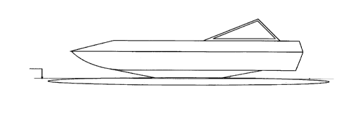
Figure 1 shows a front view of the vessel.
Figure 2 shows a side, schematic view in elevation of
the same vessel shown in figure 1.
Figures 3 and 4 correspond to a longitudinal section
and a cross-section of a generic antirolling float,
according to a preferred embodiment of the invention.
Figures 5 and 6 show the effect of the floats when the
vessel racks, it shows how the floating area of the float
and the volume submerged change.
In all the figures, same numerals correspond to the
same or equivalent parts of, according to the examples
chosen for this explanation of the vessel object of the
invention.
As it can be seen in :Eigure 1, the vessel illustrated
is provided with a superior set corresponding to the hull
(1) and at least two floats (2) which are related to the
hull by antirolling means (3), oblong inverted truncated-
conical bodies, whose superior base is fixed to the
inferior part of the hull (1), and whose lower base is
fixed to the top part of the float (2), preferably forming
only one body (2,3).
The frontal end (7) and the back end (6) of said
antirolling means (3) comprise tapered ends defining sharp
edges (8 and 9) of hydrodynamic profile for a better
displacement. The total of the floats volumes is such that
it supports the hull (1) and its cargo, above the surface
of the water.
Figures 3 and 4 show a longitudinal section and a
cross-section of an antirolling float (2,3) which is formed
by an inferior revolution body (2) with a top longitudinal
opening (a-a) from whose opposing ends two diverting walls
protrude (12 and 13) whose top endings have horizontal
sections (10 and 11), which are useful to join said body to
CA 0223~286 1998-04-20
the hull (1), and besides the structure of the truncated-
conical section they define is an antirolling means.
Having described this vessel and the examples,
modifications and improvements will occur to those skilled
in the art, all of which must be considered within the
scope of this letter patent; this scope is limited only by
the claims that follow.
- 10 -