Note: Descriptions are shown in the official language in which they were submitted.
CA 0223~0 1998-04-22
WO g7/15439 PCI'IUS96115324
BOX RLANK PRINTFR/SI OTTF~< APPARATUS
Background of the Invention
1. Field of the Invention
The present invention relates generally to the art of box blank
fol"ldlion and more particularly to a box blank forming apparatus having a
printing assembly a slotting assel,lbly and a cG~Ibol'or for selectively
interrupting printing and slotting of each blank to regulate the positiGIling and
number of i,np,i,lts and slots fo""ed in each blank regardless of the length of
the blanks.
2. Discussion of the Prior Art
Conventiol;al box making oper~tiGns involve initially die cutting a
box blank from a sheet of corrugated paper board or other suitable material
followed by creasing and slotting the blank to define the sides and end flaps ofthe blank. It is also possible to print on the blank by passing it through one or
more printing ass~,llblies priorto creasi"g and slutling.
In conventional box blank forming "lachi.)es the blanks are fed
from a supply stack by a conventional sheet feeder or the like and are
advanced through the p~illtill5~ asse,n~ es and into the clt:dsing and slotting
assen~blies by a conveyor so that each blank is i"",, intecl and includes a series
of sp~cbll slot pairs of desired length separate~J by continuous creases. Each
printing assembly includes a printing cylinder supported for rotation on the
frame of the apparatus an inking asseml ly for inking the printing cylinder and
an i""~ression cylinder opposing the printing cylinder for bringing blanks into
cGnta~ with the pri, llil ,9 cylinder for printing. The conveyor is pe, rc,rated and
several vacuum trays underlie the conveyor for ~ellllitlillg a vacuum tû be
drawn through the conveyor so that blanks are held against the conveyor as
they are conveyed between the printing and impression cylinders of each
pri"lin~ assembly and through the apparatus.
In order to perrnit each ,u, i, Itil lg assetntly to be independ-
ently removed from ~perdtion the implession cylinder of each printing
assembly is supported by eccentric hubs that allow shifting of the impression
cylinder toward and away from the printing cylinder in a di,~ction generally
transverse to the travel path of the blanks through the apparatus The vacuum
CA 0223~0 1998-04-22
WO 9'7/15439 Pcl'/us96/ls324
trays of the conveyor are also supported by the eccentric hubs so that the
conveyor can aiso be moved toward and away from the printing cylinder. By
providing this construction, it is possible to set up the machine for single color
printing by removing all but one of the printing assemblies from operation, or
to set up any number of printing assemblies for multi-color pri,)ti,)g, it beingunderstood that each assembly is used to print a single color on the blanks.
A mechanism is provided for manually tuming the eccenll ic hubs
during down time of the appardlus to shift the i~,ur~2ssion cylinder and conveyor
between a printing position adjacent the ,~ ting cylinder in which the
impression cylinder and conveyor bring blanks into CGIlt;3Ct wHh the printing
cylinder, and an interrupted position in which the impression cylinder and
conveyor are sp~ced from the printing cylinder by a distanoe sufficient to allowblanks to be conveyed past the printing cylinder without being printed.
The creasing assembly of a conver,tional machine includes an
upper drive shaft on which a plurality of creasing wheels are supported for
rotation. An anvil roller oproses the creasing wheels and defines a nip into
which the blanks are conveyed so that a series of longitudinal c,~ases are
formed in the blanks as they pass through the assembly. The slotting
assembly of a conventional box blank forming machine includes a plurality of
s~otting wheel mechanisms supported on a drive shaft. A lower anvil roller
opposes the slotting wheel mechanisn1 and d~ines a nip into which the blanks
are conveyed as they leave the creasing asse,-.bly so that at least one set of
laterally spaced slots are formed in each blank as it is conveyed through the
slotting assembly.
A problem encountered with conventional printing asse" ,blies and
with conventional slotting assemblies is that there are limitations on the size of
blanks that may be handled. In particular, since the printing cylinders and
slotting wheel mechanisms of conventional machines are of fixed circumfer-
ence, the maximum box blank length which may be fomled using such
structure is limited to lengths less than this fixed circull,rer~nce. It is not
possible to produce box blanks of a length greater than the circumference of
the printing cylinders and slotting wheel mechanisms of a particular apparatus
without fitting the apparatus with larger cylinders and slotting mechanisms.
Such modiri~tions to any apparatus are expensive, and result in a significant
amount of down time.
CA 0223~0 1998-04-22
WO 97/15439 PCI'/US96/15324
U.S. Patents 5 297 462 and 5 327 804 disclose slotting wheel
mechanisms having dynamically retractable slotter blades that allow the
formation of boxes of various skes including len~tl ,s larger than the circumfer-
ence of the slotting wheel mechanisms. The dis~lQslJre of these patents is
hereby incorporated into the present application by this ex~,,ess refer~l)ce. The
slotting wheel mechanisms discl~sed in the noted pdlents provide greatly
improved box making operations which allow the Uskipping" of cutting during
one or more successive slotting wheel revolutions. With this configuration
blanks of virtually any size may be readily slotted without slo,~ ing the slotting
wheel mechanism and without the need for employing larger diar"eter
ll,echanisms. However due to the inability of conventional printi"g assemblies
to accomlnodate similarly oversized blanks any printer/slotter apparatus
inco",ora~i"y such an improved slotting wheel ",echa,1islo would be limited to
use with blanks s,naller than the circu",rerence of the printing cylinder. Thus
the advantage gained by the improvement in the slotting wheel mechanism
would go unrealized in the printer/slotter apparatus due to the resl~ictiGIls
imposed by the printing assembly.
Objects and Summary of the Invention
It is an object of the present invention to provide a printing
asse" ILly having a means for interrupting pri, Iting on the fly during the p~ss~ge
of each blank through the assenlbly to enable a single impressiol, to be made
on each blank as the blanks are conveyed through the assel,lbly even when
the blanks are of a length gl-edler than the circu" ,fer~nce of the printing cylinder
used in the assembly.
It is another object of the present invention to combine control of
both the pri. Iting asse,obly and slotter wheel assembly of a box blank forming
spparatus to enable handling of box blanks of various sizes including sizes
greater than the circumferences of the printing cylinders and slotter wheels of
the apparatus.
In accordance with these and other objects evident from the
following description of a prefer,~d embodiment of the invention a box blank
forming apparatus is provided for forming blanks of variable length. The
apparatus inrludes a printing cylinder having a central longitudinal axis and
~ 35 being suppoi led on the frame of the apparatus for lutatiGI) about the longitudi-
nal axis and a drive means for driving rotation of the printing cylinder. An
CA 0223~0 1998-04-22
WO 97/15439 PCI'/US96/1~324
impression cylinder is supported on the frame for lotatiG, I about an axis parallel
to the longitudinal axis of the printing cylinder, and a feedil ,9 means is provided
for feeding the sheets along a travel path extending between the printing
cylinder and the impression cylinder.
The apparatus also includes an interrupting means for moving the
printing cylinder and impression cylinder toward and away from one another
between a pri, Iting position in which the impression cylinder and feeding meansbring sheets into contact with the printing cylinder and an interrupted positionin which the in.p,ession cylinder and feelli,)y means are spaced from the
printing cylinder by a distance sufficient to allow sheets to remain out of conta~;t
with the printing cylinder. A control means is provided for actuating the
interrupting means to move the printing and i",pression cylinders relative to one
another between the printing and interrupted positions during both rotation of
the printing cylinder and operation of the feeding means to enable a single
impression to be made on each sheet as the sheets are p~ssed between the
cylinders, regardless of the length of the sheets.
By providing a box forming apparatus in accordance wHh the
present invention, numerous advantages are reali~ed. For example, by
controlling the interrupting means to interrupt pri"liny on the fly during the
p~ss~ e of each blank past the printing cylinder, it is possi~ to print a singletime on each blank as the blanks are conveyed through the assembly, even
when the blanks are of a length greater than the circumference of the pri"ling
cylinder used in the assembly.
In addition, by providing a printing assemLly having this capability
of handling universally sized blanks, it is possible to combine control of the
printing assembly and of a suit~tle slotting wheel me~;l,a.,is." to pemlit printing
and slotting of such universally sized blanks in a single apparatus. Thus,
recent adYances made in the design of slolling wheel ~"echanis. ns can be used
with the present invention to increase the versatility of a box blank forming
apparatus, and both the printing and slotting operations can be controlled to
accG""),odate blanks of various sizes.
Brief Desc, iutiGn of the Drawin~ Figures
The plt f~ embodiment of the present invention is described
in detail below with reference to the attached drawing figures, wherein:
CA 0223~0 1998-04-22
WO 97115439 PCT/US96/15324
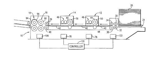
Fig. 1 is a schen)alic side elevational view of a box blank forrning
apparatus constructed in accordance with the preferred embodiment;
Fig. 2 is a schematic side sectional view of a printing assembly
forrning a part of the box blank forming apparatus illustrating the asse-,lbly in
an interrupted position in which no printing is carried out;
Fig. 3 is a schematic side se~;tiGnal view of the pri"li"g asse"lbly
illusllali"g the assembly in a printing position;
Fig. 4 is a side elevational view of the printing assembly in the
interrupted position;
Fig. 5 is a sectional view taken along line 5-5 of Figure 4;
Fig. 6 is a side sectional view of a slotter wheel assembly forming
a part of the box blank forming apparatus;
Fig. 7 is a frsgmentary sectional view of the slotter wheel
assembly illustrating a single slotter wheel mechanism of the assembly; and
Fig. 8 is an end elevational view of the slotter wheel assembly.
Detailed Desc,i,~,tiol- of the Preferred Frnbodiment
A box blank forming apparatus constructed in accorddl)ce with
the pr~fe"ed embodi")en~ is illustrated in Fig. 1 and broadly includes a frame
10 a pair of printing assemblies 12 14 a scoring assembly 16 and a slotling
asse"lbly 18. The frame includes a pair of laterally sp~d side walls 20 22
shown in Fig. 5 that are secured together by suitable means and are SIJPPO~ led
on the floor of a production facility. The spacing between the side walls
establishes the maximum width of box blanks capable of being formed by the
apparatus.
Returning to Fig. 1 a convenliGnal blank feeder assembly 24 is
supported at one end of the frame and defines the upstream end of the
apparatus. An example of a sheet feeder capable of use in the apparatus is
illustrated in U.S. Patent No. 5 338 019 the rlisclQs!~re of which is incorporated
herein by this express reference. A stack of box blanks 26 are loaded in the
feeder and fed serially by the feeder to the apparatus. A conveyor 28 extends
between the sheet feeder assembly and the scoring assembly 16 for conveying
blanks through the t~,vo printing assemblies 12 14 and dire~;ting the blanks into
the scori"y and slotting asse" Ib' e s . A pair of feed rollers 30 32 are positioned
between the sheet feeder assembly and the conveyor for guiding movement
of blanks to the conveyor and an additional upper feed roller 34 is provided at
CA 0223~0 1998-04-22
WO 97/15439 PCT/US96/lS324
the upstream end of the conveyor for holding the blanks against the conveyor
as the blanks are fed from the stack. Another upper feed roller 36 is provided
at the downstream end of the conveyor for guiding blanks into the scoring
assembly 16.
The conveyor 28 is supported by a pair of end rollers 38 40 that
are driven to move the conveyor during oper~tion of the apparatus so that box
blanks are conveyed on an upper run of the conveyor at a predeterrnined rate
through the printing assemblies and into the scoring and slotting assen,tlies.
The conveyor is forrned of a perforated ~alerial and a plurality of vacuum trays42 extend beneath and support the upper run of the conveyor. The vacuum
trays each include a pe~ rordted upper support surface and are connected to a
suitable source of negative pressure so that during operation the blanks are
drawn to and held against the upper run of the conveyor as they travel through
the apparatus.
The printing assemblies 12 14 are each adapted to print a single
color on the blanks during operation but otherwise are identical to one another.Thus the number of printing assemblies provided on the a~ ardtus determines
the maximum number of colors in which printing can be carried out. Each
printing assembly includes a printing cylinder 44 an inking assembly 46 for
inking the printing cylinder and an impression cylinder 48 for establishing
contact between the box blanks and the printing cylinder as the blanks are
conveyed between the cylinders so that an impression is made on the blanks.
The printing cylinder 44 is rotatable about a central longitudinal axis that
extends in a direction transverse to the travel path defined by the conveyor
and includes a fixed circumference on which a printing plate 50 is supported.
The impression cylinder 48 of each printing assembly 12 14 is
supported between the upper and lower runs of the conveyor 28 for rotalion
about an axis extending in a direction parallel to the longitudinal axis of the
associated printing cylinder. As illustrated in Fig. 5 an interrupting means is
provided for moving the printing cylinder 44 and i" ,pr~:ssiG, I cylinder 48 toward
and away from one another in a direction transverse to the travel path bet~Jecn
a printing position in which the impression cylinder and conveyor bring sheets
passing between the cylinders 44 48 into contact with the printing cylinder and
an interrupted position in which the impression cylinder and conveyor are
spaced from the printing cylinder by a distance surficie"t to allow sheets
CA 0223~0 1998-04-22
WO 9t/15439 PCI'/US96/15324
passing between the cylinders to remain out of col-~act with the printing
cylinder.
Preferably, the interrupting means includes a pair of eccentric
hubs 52 within which the ends of the impression cylinder are supported, and
a means for rotaling the hubs to shffl the i",~ ssion cylinder toward and away
from the printing cylinder in a direction transverse to the travel path defined by
the conveyor. Each hub 52 is elongated, presel.li,)g opposed inner and outer
axial ends. In addition, a number of longitudinally-spaced st~pped regions 54,
56, 58, 60 are formed on the outer surface of the hub bet~/~cn the axial ends.
The stepped region 54 adjacent the outer axial end of the hub includes a
toothed circumference defining a gear by which the hub is ~otaled. The
stepped region 56 adjacent the gear presenls a cylindrical outer support
surface having a diameter smaller than the root diameter of the gear. The
support surface 56 is received in a bore formed in one of the side walls 20, 22
of the frame so that the hub is rotatable, and the gear 54 and the support
surface 56 are concentric so that rotation of the gear is guided by the support
surface.
The stepped region 60 adjacent the inner axial end of the hub is
of a diar"eter smaller than the other stepped regions, and includes a cylindrical
outer circumferential surface defining a central longitudinal axis that is off-set
from the longitudinal axis defined by the gear 54 and support surface 56. The
vacuum trays 42 adjacent the impression cylinder 48 each include laterally
spaced, longitudinally extending arms 62, and each arrn extends over and is
SU~,POI led on top of the inner stepped region of one of the hubs so that when
the hubs are rotated, the ends of the vacuum trays adjace"t the printing
assembly are shifted upward and downward relative to the printing cylinder,
raising and lowe. i"g the conveyor at the same time. The region 58 adjacent to
the inner stepped region 60 defines a shoulder for maintaining the spacing
between the vacuum trays 42 and the side walls of the frame.
A longitudinally extending bore is provided in each hub, and
presents two stepped regions 64, 66. Both regions are cylindrical in shape and
concentric with one another, presenting a longitudinal axis that is off-set fromthe longitudinal axis defined by the gear 54 and support surface 56. The outer
stepped region 64 of the bore is a large diameter region within which a bearing
assembly 68 is received. The inner stepped region 66 of the bore is a small
diameter region within which an axial end of the impression cylinder is received.
CA 0223~0 1998-04-22
WO 97/15439 PCI~/US96/~5324
The ends of the cylinder are supported within the bearing assemblies 68 to
enable rotation of the impression cylinder about the axis of the bore. In
~ddition, this construction enables the i" ",ression cylinder to be shffled toward
and away from the printing cylinder when the hubs are rotated.
A transfer sha~t 70 is supported on the frame beneath the
impression cylinder for rotation about an axis extending in a direction parallelto the axis of the impression cylinder. The ends of the t,a,lsfer shaft protrudebeyond the side walls of the frame and a pair of gears 72 are fixed to the shaftat posilio"s in alignment with the hub gears 54. Thus, rot~tio,) of the transfershaft is transmitted to both hubs so that the impression cylinder is moved
toward and away from the printing cylinder without upsetting the parallel
rel.ltior,sl)ip between the impression and printing cylinders. A belt support roller
74 is mounted for rotation on the transfer shaft at a position between the side
walls of the frame, and the lower run of the conveyor 28 is supported by the
roller. Preferably, bearing assemblies are provided on the transfer shaft for
permitting this relative rotation of the support roller.
A pneumatic piston-and-cylinder actuator 76 is supported on the
side wall of the frame by a pin and may be pivoted about the pin to accommo-
date extension and retraction of a piston forming a part of the actuator. A
rotatable sprocket 80 is supported on the frame by a shaft that extends
between the side wall of the frame and a bracket 82 that is secured to the
frame. The piston includes a distal end that is connected to the sprocket by a
pin that permits relative pivotal movement between the piston and the sprocket.
A second sprocket 84 is fixed to the transfer shaft 70 immediately above the
lower sprocket, and a chain 86 is received on the sprockets 80, 84 for
transmitting rotation of the lower sprocket to the upper sprocket. When the
piston is exl~ndad from the position shown in solid lines in Fig. 4 to the position
shown in dashed lines, the sprocket 80 is rotated in a counterclockwise
direction. This rotation is transmitted to the transfer shaft 70 and through thegears 72 to the hubs 52, rola~ins~ the hubs in a clockwise direction from the
interrupted position shown in Figs. 2, 4 and 5 to the printing position shown inFig. 3. Because the impression cylinder 48 is supported on an axis eccentric
from the axis about which the hubs rotate, the ""pression cylinder is shifted
upward toward the printing cylinder 44. Likewise the ends of the vacuum trays
42 supported by the hubs are lifted into proximity with the printing cylinder
raising the conveyor 28 to the printing position.
CA 0223~0 1998-04-22
WO 97115439 PCT/US96/15324
As shown in Fig. 5, an electric brake 88 is received on the ~,dnsfer
shaft at a position adjacent to the upper sprocket 84, and is supported on the
side wall 20 of the frame. The brake is of conventional construction, and is
actuated once the impression cylinder and conveyor have been lifted to the
printing position in order to hold them in place. Likewise, the brake is
disengaged prior to lowering the impression cylinder to the interrupted position.
A conventional drive means is provided on the apparatus for
continuously driving the printing cylinder and inking assembly rollers of each
printing assembly, regardless of the position of the imp,ession cylinder relative
to the printing cylinder. Preferably, a single drive shaft extends along the frame
of the apparatus for driving all of the printing assemb~ies, as well as the scoring
and slotting assemblies and the conveyor.
As shown in Fig. 1, the scoring assembly 16 is conventional, and
includes one or more upper scoring wheels 90 supported for rotation on a drive
shaft, and a lower anvil roller opposing the scoring wheels. Each SCGI in!3 wheel
includes a means for forming a crease in a blank as the blank is conveyed into
the nip defined between the scoring wheel and the anvil roller to define a fold
about which the blank can be folded to form a box.
The slotting assembly can either take the form of one of the
slotlil)g mechanisms illustrated in U.S. Patent Nos. 5,297,462 and 5,327,804,
or can be constructed in accordance with the preferred e" ,bodiment illustrated
in Figs. 6-8 of the present application. Regardless of the e",bodi,)~ent
employed, the slotting assembly generally includes a slotting wheel mechanism
for forming slots in the blanks, and an interrupting means for interrupting
slotting on the fly during p~ss~e of each blank through the slotting assembly
to enable a single series of slots to be made in each blank as the blanks are
conveyed through the assembly, even when the blanks are of a length greater
than the circumference of the slotter wheel mechanism used in the assembly.
Turning to Fig. 8, the preferred embodiment of the slotting
assembly includes a plurality of slotting wheel mechanisms 91 s,u~ced laterally
from one another along a drive shaft 98. With reference to Fig. 7, each
mechanism includes a rotatable drive assembly 92, a rotatable blade wheel 94,
a slotter blade 96 coupled with the blade wheel, and support structure for
supporting the blade wheel so that it rotates about the same axis as the drive
assembly. The rotatable drive assembly broadly includes the drive shaft 98, a
CA 0223~0 1998-04-22
WO 97/15439 PCT/US96/15324
- - 1 0 -
drive motor for rotating the shaft, a hub 99, and a drive wheel 100 secured to
the hub. As illustrated in Fig. 6, the drive shaft includes a longitudinal keyway
which permits the hub and drive wheel to be secured for rotation with the drive
shaft.
The rotatable blade wheel 94 is provided for carrying the slotter
blade 96 for making slots in the box blanks as they are fed through the
assembly. The blade wheel is positioned adjacent the drive wheel 100 along
the drive shaft 98 and is rotatable about the shaft. The support structure
supports the blade wheel and slotter blade for rotat;on about the drive shaft and
includes a circumferential track 102 and a plurality of blade wheel rollers 104.The track is supported on a stepped end section forrned in the rear end face
of the hub 99. The track rotates with the hub and is secured thereto by a
plurality of screws. The track 102 is concentric with the drive shaft and
presents an outer circumferential, inverted V-shaped track surface for engaging
the blade wheel rollers 104.
The blade wheel rollers are rota~ably coupled with the blade
wheel by s~ hle fasteners that allow rotatiG" of the blade wheel rollers. Each
roller includes an outer circumferential groove shaped for receiving the V-
shaped track surface of the circular track 102. Thus, the blade wheel rollers
support the blade wheel for rotation about the drive wheel shaft.
The slotting assembly 18 also includes blade I otati,1y structure for
selectively rotating the slotter blade 96 relative to the drive wheel i"del~ende, Itly
of the drive shaft.
In more detail, the blade rotdliny structure broadly includes a
servo motor 106 and a gear assembly 108. The servo motor is coupled with
a suitable source of electric power, and includes an output shaft 110. The gear
assembly includes a support yoke 112, a drive pulley 114 and two idler pulleys
116. The support yoke is a metallic support member including a vertically
extending leg section and two depending leg sections. The drive pulley is
rotatably supported on the vertically e~enJi"g leg of the yoke and is rotatably
coupled with the servo motor output shaft. The idler pulleys are rotatably
mounted on the depending leg sections of the yoke. A cogged belt 118 is
positioned over the drive and idler pulleys and movement of the belt is driven
by the servo motor. The cogged belt engages teeth formed along the
circumference of the blade wheel. The blade rotating structure also includes
a controller 120 for controlling the rotational speed of the servo motor.
CA 0223~0 1998-04-22
WO 97/15439 PCT/lJS96~15324
In operation, the components of the blade lotaliny structure
cooperate for rotating the slotter btade independently of the drive assembly.
The rotational speed of the slotter blade 96 can be selectively adjusted relative
to the rotational speed of the drive wheel so that the sloffing blade can be
placed in either a cutting position or an idle, non-cutting position. For example,
the controller 120 and servo motor 106 can initially rotate the blade wheel 94
at the same rotational speed as the drive wheel 100 so that the slotter blade
makes slots or cuts during every rotation of the drive wheel. Then, the
controller and servo motor can stop the rotation of the blade wheel to allow therotatable drive assembly to continue to advance a box blank without further
slotting.
In the preferred embodiment of the apparatus, the controller 120
controls interruption of the printing assemblies and the slotting assembly to
enable printing and slotting of universally sized box blanks. A sensing element
122 is provided along the conveyor for sensing the presence of each box blank
as it is fed from the stack and for monitoring the progress of each blank through
the apparatus. Preferably, this sensing element is an optical sensor or the likethat is positioned at or near the upstream end of the conveyor. The optical
sensing element detects the presence of each blank as it p~sses the element,
and the controller 120 includes a means for tracking progress of the blank
through the apparatus based upon the driven speed of the conveyor 28.
The controller 120 includes an input means for allowing an
operator to input information relating to the ~ength of the box blanks to be
handled in any particular printing/slotting operation. In response to this inputted
information, the controller actuates the piston-and-cylinder actuators 76 of theprinting assemblies and the servo motor 106 of the slotting assembly in order
to carry out printing and slotting only at the designated positions of each blank,
and to interrupt printing and slotting along the re",ail,der of the length of each
blank, even when the length of the blanks is several times greater than the
circumference of the printing cylinders or blade wheel. Thus, it is possible to
combine control of the printing assembly and of a suitable slotter wheel
mechanism to permit printing and slotting of such universally sized blanks in a
single apparatus.
Although the present invention has been described with reference
to the preferred embodiment, it is noted that equivalents may be employed and
CA 02235550 1998-04-22
i:
WO 97/15439 PCTfUS96/15324
- 12--
substitution made herein without departing from the scope of the invention as
recited in the ciaims.