Note: Descriptions are shown in the official language in which they were submitted.
CA 02235596 1998-04-21
WO 97/22314 PCT/US96/19279
-1-
DILATOR PEEL FORCE REDUCTION
B~.CI~GI~OLrND OF THE INVIzNTION
The present invention relates to devices for separating bodily
tissues and, more particularly, to devices for separating outer wall tissues
from
inner structure tissues to dilate nasal passages of a human nose.
Humans are often subject to interior obstructing of their nasal
passages which makes breathing more difficult. Examples of such obstructing
are a deviated septum typically resulting from injury to the nose, swelling of
interior nose tissues due to allergic reactions, and the nasal symptoms
present
IO in those suffering with the common cold. The lower portion of a nostril,
immediately interior the entrance to the nostril, is known as a vestibule. The
vestibule tapers inwardly to a narrowed neck-like area called the nasal valve.
Nasal passages, posterior to the nasal valve, widen again. Nasal obstructions
commonly occur at the nasal valve to the point that the nasal valve may be
substantially blocked. Commonly, the lateral wall (i.e., the outer wall
tissues
partially about the nasal passage) at the nasal valve is loose with the result
that
the outer wall tissues draw in during the inhalation portion of the breathing
process to substantially or completely block passage of air through the nasal
passage particularly if such obstruction is present.
Blockage of the nasal passage is obviously an irritation and a
possible detriment to persons who experience it. In particular, sustained
mouth
breathing over a long period of time may cause lung irritation due to the
inhalation of foreign particles that would otherwise be filtered if the breath
had
passed through the nose. Blockage of the nasal passage is particularly
uncomfortable at night, since it is uncomfortable for many people that have a
problem to breathe through their mouth while asleep. Nasal blockages can lead
~ to sleep disturbances, sleep irregularities, or snoring or a combination
thereof.
In addition, a person with such a condition may wake often because that person
is not easily inhaling sufficient quantities of oxygen.
CA 02235596 1998-04-21
WO 97/22314 PCT/US96/19279
-2-
Where the cause of the obstruction in the nasal passage is due to
structural problems such as a deviated septum or an unusually small valve .
opening, and where the effect on breathing is relatively serious, a common
resort is to surgically attempt to correct the malformation of the nasal
passages.
However, surgery is expensive and may not ultimately correct the problem.
Where the cause is allergies or the common cold, another alternative often
used
is a medicated spray to reduce the associated swelling of tissues along the
nasal
passages. This treatment too often was insufficient to alleviate the problem,
and
there are possible detrimental effects on the tissues themselves with long-
term
use.
Because of these shortcomings experienced using these methods,
mechanical aids termed nasal dilators have been used in attempts to open nasal
passages. Such dilators have been both of the internal variety which in effect
push out the sides of the nasal passages to open them, and of the external
variety effectively pulling on some of those sides. The internal types, which
require insertion in the nasal passages, may irritate them and result in an
itching
feeling. Because of the large variety of geometries encountered in human nasal
passages, these nasal dilators often must be specifically designed for each
particular user. External nasal dilators have either been securely adhered to
the
user's nose (requiring some aid to remove) but adjustable with respect to the
force of the pull on the outer wall tissues, or have been removably adhered to
the user's nose but unadjustable single body items which provide a force
pulling
on wall tissues determined by the single body structure. The former are
difficult to remove and difficult to adjust to provide a proper force which
yields
sufficient expansion of the wall tissues without the mechanical arrangement
for
doing so becoming disengaged, knocked askew during ordinary use, or the Like.
Single body external nasal dilators have had designs developed
therefor which provide a satisfactory outwardly pulling force on tissues being
CA 02235596 2004-04-27
-3-
dilated without discomfort, and which can also be relatively easily put in
place
for use as a dilator while yet being relatively easily removed. This latter
feature has been accomplished in dilators using spring containing bodies with
pressure sensitive adhesives, and the peel forces, which are generated by the
relatively stiff spring ends along with motion of the skin under and adjacent
to
such dilators adhered thereto using such adhesives, has been prevented from
causing the dilators to separate from the skin through a suitable geometry at
the ends thereof. One possibility is to use spring members in the dilator body
which are of shorter length than the length of the body in which they are
contained so that centering the position of such spring members in that body
leaves each of the spring member ends spaced apart from the corresponding
body ends. This possibility was shown in earlier filed copending U.S. Patent
Application by B.C. Johnson entitled "Nasal Dilator" filed on January 19,
1994,
which has issued as Patent No. 5,533,499. In effect, the portions of the body
ends past the spring members ends serve as body extensions that resist the
peel forces occurring at the ends of these spring members. Unfortunately, the
need to individually position spring members during the manufacturing
process is expensive and subject to errors.
Alternatively, the central end portions of the dilator body at the
opposite ends thereof past the spring member ends can be cut out during
manufacture so that the end edges reach back to the ends of the short spring
members or, more practically, the springs, rather than being short and
positioned, can extend for the length of the dilator body before being cut
into
units with the central end portions being cut out along with the cutting into
units. This will leave body side extensions without any spring member
portions therein, and these side extensions will extend past the ends of the
spring members after such cutting as described in earlier filed copending U.S.
Patent Application by W.J. Doubek, D.E. Cohen and B.C. Johnson entitled
"Nasal Dilator" filed on April 20, 1993, which has issued as Patent No.
5,533,503. However, the adhering extensions used in the geometry of the
CA 02235596 2004-04-27
-4-
dilator ends described there to prevent that dilator from peeling away from
the
skin restrict the possible end shapes which might otherwise be used and,
because such extensions do extend past the spring members in the dilator
body, they unavoidably result in some waste of material in the manufacturing
process. This situation can be eased by eliminating any central end portions
being cut out and, instead, just providing relief cuts between the spring
members and the side extensions portions. Such an arrangement, however,
will result in a small amount of peeling of the central end portions not cut
out
as they were in the previous version. The resulting peeled away central end
portions will be subject to catching onto objects brought into contact with,
or
near to, the wearer's nose, collecting dirt, becoming unsightly, causing
itching,
etc.
In addition, the skin under those extensions accumulates some
moisture therein due to the reduced evaporation therefrom resulting from the
presence of the extensions over that skin which weakens the structure thereof
at such locations. At dilator removal, the forces between the dilator
extensions and the skin change from being primarily peel forces to being
primarily sheer forces which are much greater in magnitude due to the nature
of the pressure sensitive adhesive used on the extensions, and so there is a
potential for damaging the weakened skin upon the introduction of the greater
magnitude of sheer forces during removal of those extensions from the skin.
On the other hand, the omission of the extensions or any relief cuts
between the spring force member and the adjacent side portions of the dilator
leads to the spring members reaching the extreme end edges of the dilator.
The substantially constant spring force along the dilator from end edge to end
edge provided by the resilient members therein, along with the relatively high
stiffness of short sections of the spring back from the end edges, leads to
the
occurrence of peel forces due to the motion of the skin beneath the dilator
CA 02235596 1998-04-21
WO 97/22314 PCTJUS96119279
-5-
during ordinary use that are sufficient in a significant number of dilator
uses to
cause the ends of the dilator to begin to disengage from the skin of the user
therebeneath. Thus, there is a desire for a single body dilator structure that
reduces waste in manufacture, allows design freedom for the ends of dilators,
and reduces the risk of skin damage during separation of the dilator from the
user's skin.
SUMMARY OF THE INVENTION
The present invention provides a dilator which in use tends to
force wall tissues in the human body, on which it is engaged under force, away
from one another. The dilator comprises a truss having a pair of spaced-apart
end surfaces which provides a restoring force tending to separate those
surfaces
if they are forced toward one another. The end surfaces have engagement
means adhered thereto which can engage exposed surfaces of such outer wall
tissues sufficiently to remain engaged against such restoring force. This
restoring force is provided in part by at Least a first resilient band of a
selected
thickness extending between end edges of the opposite ends of the truss,
adjacent the end surfaces, where this band has a plurality of notches located
therein exceeding at least a third of that thickness which are directed across
the
band to reduce the restoring forces at those Locations. Such a notch may
comprise a separation at the location thereof between selected portions of
said
first resilient band with this separation surrounded by a corresponding
separation
edge thereabout intersecting a first surface of the first resilient band.
These
notches can be in two groups near the opposite end edges of the resilient band
in the truss with the deepest or Largest notches closest to the ends and the
others
getting successively Less deep or smaller in sequence toward the middle of the
truss. A second resilient band can also be provided in the truss spaced apart
entirely or mostly from the first resilient band to also extend between the
end
edges thereof, and which also has notches provided therein.
CA 02235596 1998-04-21
WO 97/22314 PCT/LJS9G/19279
gRTFF DEBCRIPTIQN OF THE DRAWFNG~
Figure 1 shows a pictorial view of a portion of a human face
including the nose, and of a dilator embodying the present invention engaged
with that nose;
Figure ZA shows an exploded pictorial view of components of the
dilator of the present invention shown in Figure 1;
Figure 2B shows a fragmentary view of a portion of Figure
2A;
Figure 3 shows a pictorial view of the same portion of the human
face shown in Figure 1 absent any dilator;
Figure 4 shows a cross section view taken from the view of
Figure 3 with the nose shown being in a state of relatively little flow of air
through the nasal passages;
Figure 5 shows a cross section view similar to that of Figure 4
with a reduced air flow through the nasal passages;
Figure 6 shows a cross section view taken from Figure 1 with an
appreciable air flow through the nasal passages;
Figure 7 shows a pictorial view of an alternate embodiment of the
dilator of the present invention;
Figure 8 shows a pictorial view of a portion of a human face
including the nose, and of the dilator of Figure 7 engaged with that nose;
Figure 9 shows a pictorial view of an alternate embodiment of the
dilator of the present invention;
Figure 10 shows a pictorial view of an alternate embodiment of
the dilator of the present invention;
Figure 11 shows a pictorial view of an alternate embodiment of
the dilator of the present invention;
Figure 12 shows a pictorial view of an alternate embodiment of
the dilator of the present invention;
CA 02235596 1998-04-21
WO 97/22314 PCT/US96/19279
_')_
Figure 13 shows a pictorial view of a portion of a human face
~ including the nose, and of the dilator of Figure 12 engaged with that nose;
Figure 14 shows a pictorial view of an alternate embodiment of
the dilator of the present invention;
Figure 15 shows an exploded pictorial view of an alternate
embodiment of the dilator of the present
invention;
Figure 16 shows an exploded pictorial view of an alternate
embodiment of the dilator of the present .
invention;
Figure 17 shows an exploded pictorial view of an alternate
embodiment of the dilator of the present
invention;
Figure 18 shows an exploded pictorial view of an alternate
embodiment of the dilator of the present
invention;
Figure 19 shows an exploded pictorial view of an alternate
embodiment of the dilator of the present
invention;
Figure 20 shows an exploded pictorial view of an alternate
embodiment of the dilator of the present
invention;
Figure 21 shows an exploded pictorial view of an alternate
embodiment of the dilator of the present
invention; and
Figure 22 shows an exploded pictorial view of an alternate
embodiment of the dilator of the present invention.
DETAILED DESCRIPTION OF THE PREFERRED EMBODIMENTS
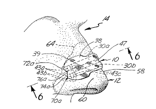
A dilator, 10, embodying the present invention is shown in Figure
1. Dilatoi 10 is shown being used as a nasal dilator on a subject in being
engaged with a nose, 12, seen as part of a portion of a human face, 14.
The elements used in the construction of dilator 10 can be seen
in the exploded pictorial view of that dilator shown in Figure 2A. As seen
, there, dilator 10 comprises a unitary, or single body, truss member, 16,
having
a strip of base material, 18, with a first end region, 20, and a second end
region, 22, joined to first end region 20 by an intermediate segment, 24. The
CA 02235596 2004-04-27
_ g _
width of intermediate segment 24 is less than the width of first and second
end regions 20 and 22 for the comfort of the user because of covering less of
the user's skin. Base material 18 is preferably formed of a polyester fabric
that allows the skin on user nose 12 to exchange gases with the atmosphere
relatively easily to maximize comfort and minimize irritation during use. A
suitable, nonwoven, spun-laced, 100 percent polyester fabric from which to
form base material 18 is available from E.I. DuPont Nemours & Co. under the
trade name SONTARAT"". SONTARAT"" fabric typically has a breaking
strength property in a ratio of approximately 2:1 as determined by the
machine direction (MD) or warp, relative to the cross direction (XD) or fill,
of
the fabric. In addition, SONTARAT"" fabric typically has an elongation
percentage ratio of approximately 3:1 as determined by the resulting
elongations for equal forces in the cross and machine directions of the
fabric.
The machine direction of the fabric is parallel to the longitudinal extent of
base
material18.
Truss 16 further includes resilient means, 26, secured to a first side,
28, of base material 18. Resilient means 26 includes a first resilient band,
30a, and a second resilient band, 30b. First resilient band 30a has a first
end,
41 a, and a second end, 42a. Second resilient band 30b has a first end, 41 b,
and a second end, 42b. First and second resilient bands 30a and 30b are
each formed of a polymer material. For example, an industrial grade, biaxially
oriented polyester such as MYLART"" Type A offered by E.I. DuPont Nemours
& Co. which is cut to approximately 0.080 in. to 0.135 in. in width from 0.010
in. thick stock has been found suitable. Using a polymer material which is
relatively thin as just described for each of first and second resilient bands
30a and 30b enhances the axial, torsional flexibility of each of these bands
about the longitudinal extent of each depending on the width of the bands
actually used.
A sequence of three notches, 43a, 43b, and 43c, is shown in each of
first and second resilient bands 30a and 30b. Notches 43a, nearest the
extreme ends of each of first and second resilient bands 30a and 30b, is the
CA 02235596 1998-04-21
WO 97/22314 PCT/US96/19279
-9-
deepest notch and, for example, in a resilient band with a 2.60 in. length and
a 0.135 in. width, this notch would be typically 0.15 in. inward from the
resilient band end nearest thereto with a depth of 80 gb to 100 9~ of the
thickness
of that resilient band, typically 9096 to 10030 of the thickness. The next
notches
inward in this example, notches designated 43b, would be each located 0.10 to
0.20 in. closer to the middle with a depth of 60°~ to 906 of the
resilient band
thickness, typically 709. Finally, the last notch shown in each sequence and
closest to the middle of the resilient band, notches designated 43c, would
typically be another 0.10 to 0.20 in. closer to the middle but with a depth of
only 40 R~ to 70 ~Xo of the resilient band thickness, typically around 40 % .
Further notches could be included in sequence extending closer
to the middle of the corresponding resilient bands, and different depths for
each
of the notches could be used. The effect of introducing these notches ever
less
deep in the sequence thereof toward the middle is to monotonically decrease,
or
taper off, the effective spring constant along the two half lengths of each of
the
resilient bands starting from the middle thereof. The deepest notches reduce
effective spring constant the most so that locating them at the ends of the
bands
is quite effective in reducing the peel forces at the ends of the resilient
bands
resulting from the bands spring force and the motion of the skin therebeneath.
The other notches of lesser depth as one proceeds to go to the center of the
band
reduced the spring constant less at each location thus giving an increasing
effective spring constant along the directions from the ends of the resilient
bands
toward the center. As a result, the desired pull on the outer wall tissues of
the
user's nose can be set by the type of material, length, thickness and width to
. 25 provide the desired pull on those tissues while being reduced
sufficiently to, as
will be described, avoid undue peel forces occurring between the pressure
sensitive adhesive beneath the ends of these bands and the skin to which it is
attached.
CA 02235596 1998-04-21
WO 97/22314 PCT/US96/19279
-i0-
First and second resilient bands 30a and 30b are secured by first
and second flexible strips of interface adhesive material, 31a and 31b, to a
first
side, 28, of base material of strip 18. First interface adhesive material
strip 31a
has a first end, 33a, and a second end, 34a. Second interface adhesive
material
strip 3Ib has a first end, 33b, and a second end, 34b. First and second strips
of interface adhesive material 3ia and 31b are of the same shape and size in
the
plan view thereflf as are first and second resilient bands 30a and 30b,
respectively, in a plan view thereof.
First resilient band 30a is secured by adhesive material strip 31a
to base material strip 18 adjacent a first edge, 32, of intermediate segment
24
thereof. Second resilient band 30b is parallel to, and spaced apart from,
first
resilient band 30a, and is secured by adhesive material strip 31b to base
material
strip 18 adjacent a second edge, 36, of intermediate segment 24 thereof. First
and second resilient bands 30a and 30b are oriented, as stated above,
generally
i5 parallel to one another and substantially parallel to the longitudinal
extent of
base material strip 18. Each of interface adhesive material strips 31a and 31b
is preferably an acrylic, pressure sensitive bio-compatible transfer tape
adhesive
material such as that designated 3M 1509 offered by, and available from,
Minnesota, Mining & Manufacturing Company, Inc., or an acrylic, pressure
sensitive bio-compatible transfer adhesive material such as that designated
1368B
offered by, and available from, the Betham Corporation or such as that
designated 1524 offered by, and available from, Minnesota, Mining &
Manufacturing Company, Inc.
Truss 16 further includes a flexible strip of top material, 38,
having a first end region, 39, a second end region, 40, and an intermediate .
segment, 47, with the same size and shape in plan view as base material strip
18 has in plan view. A bottom surface 35, of top material strip 38 includes a
layer of an adhesive substance, 48, that extends over the first and second end
regions 39 and 40 and over an intermediate segment 47 thereof. Adhesive
CA 02235596 1998-04-21
6'VO 97/22314 PCT/LTS96/19279
-11-
substance 48 is a porous, acrylic, pressure sensitive bio-compatible adhesive.
Top material strip 38 covers first and second resilient bands 30a and 30b and
first side 28 of base material strip 18, and is secured thereto by adhesive
substance layer 48.
Top material strip 38 aids in preventing first and second resilient
bands 30a and 30b from separating from base material strip 18 and interface
adhesive material strips 31a and 3Ib in those situations where truss 16 is
flexed
by movement of that skin thereunder on which it is being used. In addition,
top
material strip 38 limits to some degree base material strip 18 by together
providing a stiffer material in the major plane thereof to provide a
geometrically
more stable combination which permits installing and removing dilator 10 more
easily. Top material strip 38 is preferably a porous, nonwoven material with
adhesive substance 48 provided thereon such as that designated 3M 1533 offered
by, and available from, Minnesota, Mining & Manufacturing, Inc.
Further in connection with base material strip 18 in Figure 2, a
second side, 44, thereof has a layer of an adhesive substance, 46, extending
over it including over first and second end regions 20 and 22 and over
intermediate segment 24 on that side thereof. Adhesive substance 46 is a
porous, acrylic, pressure sensitive bio-compatible adhesive. Adhesive 46 is
used
to engage dilator 10 with the skin of the outer wall tissue on which that
dilator
is to be used, the outer wall of nose 12 in Figure 1. A fabric suitable for
forming base material strip i 8 can be obtained with adhesive substance 46
provided thereon such as the material 3M 1776 offered by, and available from,
Minnesota Mining & Manufacturing, Inc.
. 25 Adhesive substance 46 is covered before use by a pair of release
liners including a first release liner, 49, and a second release liner, 50.
These
release liners cover adhesive substance 46 on first end region portion 20 and
second end region portion 22 of base material strip 18 with an extended
portion,
51, of first release liner 49 and an extended portion, 52, of second release
liner
CA 02235596 1998-04-21
WO 97/22314 PCT/US96/19279
-12-
50 covering the adhesive substance 46 portion on intermediate segment 24 of
base material I8. First and second release liners 49 and 50 are readily .
removable from adhesive substance 46.
As can be seen in Figures 3 and 4, a human nose I2 includes a
first nasal passage, 54, a second nasal passage, 56, and a portion of nose I2
generally referred to as a bridge, 58, of that nose, extending between but
outside of first and second nasal passages 54 and 56. The state of the nasal
passages in Figure 4 is that occurring in the portion of the breathing cycle
in
which there is little airflow occurring therethrough, and are the nasal
passages
of a person that is neither sick with an ailment which has symptoms involving
the nasal passages nor has had nasal passage injury. Thus, nasal passages 54
and 56 are relatively open and can easily pass airflows.
During the peak of an inhalation in the breathing process, the
slight decrease in pressure inside the nose Leads to a slight drawing in of
the
outer walls of the nose. If, however, there has been an injury to the nasal
passages leading to some obstructing thereof, or there is a swelling of the
tissues
Lining those passages because of an allergic reaction or sickness, the tissues
forming outer walls, 60 and 62, on the exterior sides of first and second
nasal
passages 54 and 56, respectively, inhalations can Lead to even greater
decreases
in air pressure as air velocity through the narrowed passages increases as the
breather attempts to get a full breath. Outer wall tissues 60 and 62 then tend
to be more strongly drawn in to the nasal passages as can be seen in Figure 5,
even to the point in some circumstances of the passages collapsing to near
closure. The portion of the outer wall tissues 60 and 62 so drawn in during
inhalation is that located between the end of the nasal passage bone and the
skull
shown in a dashed line in Figures 1 and 3, and the entrance to nasal passages
54 and 56. Such drawings in of the outer wall tissues 60 and 62, as a result,
cause further nasal blockage. The severity of this nasal blockage condition
CA 02235596 1998-04-21
6V0 97!22314 PCT/US96119279
-13-
depends on how narrow the nasal valve is in the person involved. Nasal dilator
~ 10 is provided as a remedy for this nasal blockage problem.
In use, nasal dilator 10 is engaged with the skin on outer wall
tissues 60 and 62 of nose 12 by adhesive substance 46 after the removal of
first
S and second release liners 49 and 50 therefrom. Figures 1 and 6 show nasal
dilator 10 placed on the exterior skin of nose 12 such that intermediate
segment
24 traverses bridge S8 of nose I2 with first and second end regions 20 and 22
held in contact with outer wall tissues 60 and 62 of first and second nasal
passages 54 and 56, respectively, by adhesive substance 46. Adhesive substance
46 located at first and second end regions 20 and 22 of dilator 10, and at
intermediate segment 24, releasably engages unitary, or single body, truss
member 16 to outer wall tissues 60 and 62 and bridge 58 of nose 12.
The resiliency of first and second resilient bands 30a and 30b, the
tendency of these bands to return to their normally planar state once having
the
i5 ends thereof forced toward one another, provides an outward pull on outer
wall
tissues 60 and 62 when nasal dilator 10 is properly positioned on nose 12.
This
outward pull counters the drawing in force on outer wall tissues 60 and 62
during inhalation, and so acts to stabilize the position of those wall tissues
60
and 62 during such inhalations. The flexibility of base material 18, interface
adhesive materials 3Ia and 31b, and top material 38, along with the resiliency
of first and second resilient bands 30a and 30b together with the flexibility
they
exhibit due to having a relatively slight thickness, all allow nasal dilator
10 to
closely conform about the curves of nose 12 of each individual wearer to
increase the comfort of that person during use. The relatively slight
thickness
of resilient bands 30a and 30b also enhances the axial torsional flexibility
of
truss member 16 about the longitudinal extent thereof which further increases
. wearer comfort and aids in maintaining adhesion of adhesive substance 46 to
the
wearer's nose.
CA 02235596 1998-04-21
WO 97/22314 PCT/US96/19279
-14-
Further, the spun-laced fabric structure of the fabric strip serving
as base material strip 18 permits limited, primarily plastic but somewhat
elastic, .
deformation within the thickness of base maxerial 18. This deformation
property
spreads out through that strip delaminating forces such as may be caused by
(1)
S the inherent tendency of resilient bands 30a and 30b to return to their
normally
planar state, (2) surface configuration differences between those resilient
bands
and nose 12 of a wearer, and (3) displacement of unitary, or single body,
truss
member 16 relative to outer wall tissues 60 and 62 as a result of shear,
tensile,
cleavage or peel forces imparted at or to those outer wall tissues and truss
member 16 due to wearer skin movement (e.g. nose gestures) or contact with
an exterior object such as a pillow. Such delaminating forces tend to cause
nasal dilator 10 to be inadvertently detached from nose 12 of a wearer. In
spreading out these delaminating forces, base material strip 18 acts as a
mechanical buffer to prevent transfers of focused forces to adhesive substance
46, and so to the skin of nose 12 of the wearer. Providing the transfer of
focused delaminating forces substantially eliminates itching sensations caused
by
the separation of adhesive substance 46 from portions of the skin under
dilator
IO that a wearer I4 may experience if such delaminating forces were focused
at the skin of nose 12.
The range of dilating force provided by dilator 10, that is, the
outward pull provided to outer wall tissues 60 and 62 by the resiliency of
truss
member 16 due to resilient bands 30a and 30b therein has been found to have
a suitable range of from 5 to 50 grams or more. Under 10 grams of such
dilating force is usually insufficient to help most wearers with any
significant
degree of nasal blockage during inhalations. However, if the nasal blockage is
mild enough, a positive effect may be noticed by the wearer with as Iittie as
5
grams of dilating force provided by dilator 10. A dilating force in excess of
40
grams is often somewhat obtrusive and uncomfortable for many wearers, though
not all, wearers of such a dilator.
CA 02235596 1998-04-21
WO 97/Z2314 PCTlUS96/19279
-1S-
As a result, nasal dilator 10 is fabricated to provided typically
- from 20 to 30 grams of dilating spring force on outer walls 60 and 62 of
nasal
passages 54 and 56, at least at locations inwardly from notches 43a, 43b and
43c along resilient bands 30a and 30b. Each of these resilient bands provides
a portion of this total. The dilating spring force at these notches out to the
ends
of dilaxor 10 are progressively reduced as described above to thereby reduce
the
peel forces experienced at the ends of dilator 10. Since the two resilient
bands
30a and 30b used in unitary, or single body, truss member 16 are generally of
equal proportions with generally similarly located and sized notches 43a, 43b
I0 and 43c provided therein, each of bands 30a and 30b provide approximately
one-half of the total dilating spring force occurring at each location along
the
length of dilator 10, but could be of different widths or lengths to allow
varying
of the dilating force along the length of the nose.
As can be best seen in Figures 1 and 6, unitary truss member 16,
comprising base material strip 18, interface adhesive material strips 31a and
31b, top material 38, and first and second resilient bands 30a and 30b,
include
a first scalloped edge, 70a, at one end, and a second scalloped edge, 70b, at
the
opposite end of that member. First scalloped end edge 70a is formed by first
end region 20 of base material strip 18 and first end region 39 of top
material
38, and by first ends 41a and 41b of resilient bands 30a and 30b, and first
ends
33a and 33b of adhesive strips 31a and Sib. Second scalloped end edge 70b is
formed by second end region 22 of base material strip 18 and second end region
40 of top material 38, and by second ends 42a and 42b of first and second
resilient bands 30a and 30b, and by second ends 34a and 34b of adhesive strips
31a and 31b. Because of the similarity of first and second scalloped end edges
70a and 70b, only one need be described to understand both which will be first
- scalloped end edge 70a.
First scalloped end edge 70a includes two protrusions, 72a and
74a, separated by a setback portion, 76a. The protrusion extent of protrusion
CA 02235596 1998-04-21
WO 97/22314 PCT/US96/19279
-16-
72a and 74a are set by the cutting die used in forming a dilator 10 from a
continuous strip of combined materials matching the materials in a truss
member .
16, the protruding portions being chosen in dilator 10 to be formed by first
ends
41a and 41b of resilient bands 30a and 30b, respectively, in the corresponding
first ends 33a and 33b of adhesive material strips 31a and 31b. Since
protrusions of the resilient bands are outermost, the die cutting a truss
member
16 from a continuous strip need not waste any resilient band material. ~ The
protrusions containing resilient bands from one truss member lb will match
those from the next truss member 16 so that essentially no material need be
cut
out between them and lost in the fabrication process. Due to the setbacks from
the protrusions contained in the resilient bands, on either side of each, that
is
including setback, 76a, and the material on the outer sides of the resilient
bands,
there will be some Loss of this material at each cutting between adjacent
truss
member portions. However, the loss of these materials is significantly reduced
in addition to the near elimination of any loss of resilient band material.
Therefore, the resulting economies in the manufacturing process in using
continuous resilient bands extending to the ends of the dilator are
significant.
Thus, dilators can be fabricated without undue waste in a
continuous fabrication operation. However, these dilators of the shown design
do not result in inadvertent peeling at the ends thereof during use, that is,
delamination of the end region from the skin of a wearer's nose, because of
facial gestures, forces from external objects like pillows during sleep, and
the
like. This is because the spring constant is much reduced toward each of the
opposite ends of the dilator by the notches 43a, 43b and 43c provided toward
the ends of the resilient bands 30a and 30b provided in that dilator. Hence, a
dilator is provided in an efficient fabrication process which permits
tailoring the
spring constant along the lengths thereof to desired values at various
locations
along that length.
CA 02235596 1998-04-21
WO 97/22314 PCT/US96/19279
-17-
As can be seen in Figure 2, in the situation where resilient bands
' 30A and 30B are adhered to base material strip 18 by adhesive strips 31A and
31B, respectively, before notches 43A, 43B and 43C are cut into these
resilient
strips, base material strip 18 will by this adherence keep any portions of
resilient bands 30A and 30B in the relative same position should the cutting
of
the notches go so far as to separate portions of these resilient bands form
one
another. This is true also even if the cutting action should sever the portion
of
base material strip 18 underneath the notches since the strip material extends
outward from either side of these resilient strips. This retention action is
supplemented by top material strip 38 if it also is adhered to resilient bands
30A
and 30B prior to such notch cutting so that the notching cut is made through
this
top material strip, again because the strip extends past either side of these
resilient bands.
However, the provision of base material strip 18 and top material
strip 38 in dilator 10 results in added in added costs in fabricating that
dilator.
These costs are avoidable if dilator IO is fabricated from just the resilient
band
material by using that material to again form just a single body structure
again
having a porous (needed if the band has been perforated by tiny holes to aid
moisture evaporation, otherwise not), acrylic, pressure sensitive bio-
compatible
adhesive applied on one side thereof. This adhesive provides, as before, the
engagement means for adhering the resulting dilator to the skin of wearer's
nose
12 and aids in spreading out the delaminating forces tending to cause that
dilator
to be inadvertently detached from nose 12 of the user. However, this spreading
of the delaminating forces by the adhesive will typically be insuff cient to
prevent peeling unless notches again are provided in some form in the
resilient
material forming such a dilator.
One such possible notching arrangement, which would retain the
ends of the resilient band or the dilator with the rest of the dilator even
though
the notch extended therethrough, is to form the notches in the band so as to
not
CA 02235596 1998-04-21
WO 97/22314 PCT/US96lI9279
-18-
reach either of the sides of the resilient material band forming the body of
the
dilator. This arrangement would thereby leave a portion of the band on either
side of a notch between the ends of that notch and the corresponding side of
the
band. The band material remaining between the notch and each side of the band
will, of course, exhibit a much reduced spring constant to thereby reduce the
outward force present at the corresponding end of the dilator to thereby
reduce
the tendency of the dilator ends to peel away from the wearer's skin. However,
that remaining band material will still retain in the dilator the dilator end
portions, those portions of the band between each of the notches and the
corresponding one of the opposite end edges, without the need for either a
base
material strip or a top material strip despite the notch be cut entirely
through the
band.
That is, this remaining band material between a notch and the
sides of the band or dilator will retain the end of the band beyond the notch
and
will also bend quite easily to thereby reduce the peeling force at the end
edge
by, in effect through such bending, converting that peeling force into a sheer
force which is much better resisted by the adhesive material engaging the
dilator
to the skin of the wearer's nose. Such notches in the resilient band forming
the
dilator would typically be cut at the same time the band itself was die cut
out
of resilient material stock to assure there would always be that small amount
of
remaining material between each notch and the sides of the resulting band. The
band and the notches may be cut from the adhesive covered side of the band to
the opposite side so that the notch sidewalls and the adhesive covered surface
of the band meet at any obtuse angle to avoid a sharp edge being positioned
next
to the wearer's skin which could result if the cut is made from the other
side.
Although such notches could be just simple "V" cuts in the band
material as before, or just slits cut into the band, a significantly wider
notch can
be used instead extending all the way through the band but narrower in extent
CA 02235596 1998-04-21
WO 97/22314 PCTlUS96119279
-19-
than the width of the band, i.e. an elongated hole in the band, such as is
shown
in the bottom side pictorial view of such a dilator in Figure 7. There,
dilator
IO is formed of a single resilient band strip, 80, having a porous, acrylic,
pressure sensitive bio-compatible adhesive, 8I, (indicated by stippling in
Figure
S 7) coated on what would be the bottom side thereof during use on a wearer's
nose. Resilient band 80 is again formed of the same resilient polymer material
used for bands 30A and 30B, an industrial grade, biaxially oriented polyester,
such as MYLAR~ Type A as indicated above, of a width of approximately
0.375 in. in its narrowest portion at the middle of the band and of a somewhat
greater width at the ends past the indentation at the middle portion and,
perhaps,
a bit thinner to maintain the same effective spring constant in view of the
increased width..
A pair of elongated openings, 82, or holes, are provided through
adhesive 81 and resilient band 80 as the wide notches to form substantial
IS separations between some portions of hand 80, and which extend near but do
not
reach the sides of the band, and which are each located near one of the
opposite
end edges of that band. Although shown as openings completely through band
80 to thereby completely separate surrounded interior portions of that band
from
the rest of the band, openings 82 need not extend all the way through band 80.
Even if they for the most part do extend all the way through band 80, the
portions previously filling holes 82 may be left in place without removal
thereof. In any of these forms, openings 82 as a result substantially separate
the
remaining central portion of band 80 from the end portions thereof on the
opposite sides of openings 82. In addition, resilient band 80 can be
perforated
_ 25 with a large number of tiny openings over substantial areas, or all of
that band
(not shown) to aid moisture developing thereunder to evaporate.
The material portions, 83, remaining between the ends of
openings 82 and the sides of band 80 will retain end portions, 84, each
located
between a corresponding opening 82 and the nearby one of the opposite end
CA 02235596 1998-04-21
WO 97!22314 PCTlUS96/19279
-20-
edges of band 80. This retention of end portions 84 by material portions 83
will
occur even if openings 82 continue completely through band 80. Remaining
material portions 83 will also allow end portions 84 to bend sharply and
relatively easily with respect to the central portions of band 80 to permit
those
end portions follow the contours of the sides of a user's nose without large
outwardly directed forces resulting at the ends thereof. This araangement
effectively changes what would otherwise be significant peel forces at the
outer
ends of these end portions 84 into sheer forces that are much better resisted
by
adhesive 81.
Figure 8 shows the positioning of dilator 10 of Figure 7 on nose
I2 as part of human face 14, and typically positioned there at the same
location
as were the previously described dilators. The version of the homogeneous
single body dilator shown in Figures 7 and 8 shown in these figures has just
one
opening 82 shown located near each of the opposite ends of strip 80 to provide
a reduced effective spring constant at those locations in strip 80 to result
in
reduced outward forces at the opposite ends of that strip. Alternatively, a
series
of such openings, or wide notches, can be provided near each of the opposite
ends of strip 80 to provide a reduced effective spring constant at those
locations
in strip 80 that extends over a greater distance along the length of that
strip so
that the change is less abrupt. This distributed reduction in spring constant
may
be further adapted to a desired distribution by choosing different lengths for
the
openings in such a series so as to leave more or less material between the
ends
of the openings and the sides of the band. Thus, by having the opening 82
nearest the center of band 80 in the series thereof the shortest with each
successive opening in this series toward the nearest end of band 80 being
longer,
the effective reduction in the spring constant can be tapered downward in
value
from the maximum value toward the center of that band.
Figures 9, 10 and 11 show that the openings 82, or the notches,
can be formed of various alternative shapes to also affect the distribution of
the
CA 02235596 1998-04-21
WO 97/22314 PCT/US96119279
-21-
spring constant reduction as they are not confined to being the elongated
opening shape shown for openings 82 in Figures 7 and 8. Thus, in Figure 9,
a top pictorial view of dilator 10 is provided showing openings or cut through
notches that are alternatively shaped to those in Figures 7 and 8, the
openings
in this instance being symmetrical round holes, 82', rather than the elongated
openings, or rounded end rectangular shapes, followed by openings 82 in
dilator
of those figures.
Figures 10 and 11 each show a pair of cut slits as the notches
rather than broader openings as the substantial separation forming the notches
10 'between the end portions and the central portion of dilator 10. Figure 10
shows
a pair of slit openings, 82", following a portion of the circular edge of
openings
82' in Figure 9 somewhat beyond half of the circle (but could follow a portion
of an oval shape or of other closed curves) so as to leave the interior of the
circular portion attached to the remainder of band 80 along the sides thereof
closest to the center of that band. Slit openings 82" are continued past the
half
circle points so as to have the ends thereof point away from the sides of band
80 to thereby minimize the possibility of crack propagation from the ends of
the
slits to the sides of that band.
Alternatively, in Figure 11, slits following straight lines are the
substantial separations cut into band 80 hut with small circular openings
provided at each end thereof to thereby together provide a pair of openings,
82"', the circular opening portions provided to again prevent any crack
propagation from the ends of the slits to the sides of band 80. This crack
propagation is most likely to occur during the die cutting of these openings
in
_ 25 dilator 10 rather than during use since such use usually occurs on just a
single
occasion for each dilator resulting in relatively little repeated flexing
remaining
- material portions 83.
Notches or broader openings can also be used to provide
increased flexibility of resilient band 80 along the length and across the
width
CA 02235596 1998-04-21
W~ 97/22314 PCT/LTS96/19279
-22-
of that band in addition to providing such flexibility toward each of the
opposite
ends of band 80 along the width and across the length thereof as shown for
dilator 10 in Figures 7, 9, IO and I 1. Thus, Figure I2 shows not only a pair
of elongated openings 82 substantially separating end regions 84 from the
central
remainder of resilient band 80 as in the dilator 10 of Figure 7, but also
shows
a longitudinal opening, 85, provided transverse to and intersecting openings
82
to then extend beyond them to nearly reach the length of dilator 10 between
the
opposite ends thereof to thereby substantially separate side portions of band
80.
IO As a result, there are further remaining material portions, 86,
provided between the ends of longitudinal opening 85 and the corresponding one
of the opposite end edges of dilator 10. The presence of longitudinal opening
85 extending so close to the opposite end edges of dilator 10 allows the two
side
portions, or longitudinal subbands, 87, formed as a result of providing
Iongitudinai opening 85, to bend sharply and relatively easily with respect to
each other at remaining material portions 86 to thereby increase the
flexibility
of resilient band 80 across its width. In effect, subbands 87 closely
approximate
the behavior of resilient bands 30A and 30B in dilator 10 of Figure 2. Again,
a bottom pictorial view of dilator 10 is shown in Figure 12 so that adhesive
81,
provided on resilient band 80 at end regions 84 and subbands 87 as represented
by the stippling present thereon, is exposed to view.
Figure 13 shows dilator 10 of Figure I2 positioned on nose 12
seen as part of a portion of human face 14. Again, dilator 10 in Figure 13 is
typically positioned on nose 12 at the location used for previously described
dilators.
Further flexibility across the width of dilator 10 can be provided
by the use of an additional longitudinal opening in resilient band 80
paralleling
longitudinal opening 85 in dilator I0 of Figure I2. The result is shown in
Figure 14 where there is now shown a pair of parallel longitudinal openings,
CA 02235596 1998-04-21
WO 97/22314 PCT/US96/19279
-23-
85', provided in resilient band 80 to thereby form three subbands, 87', each
of
w longitudinal openings 85' intersecting both members of a corresponding pair
of
transverse openings, 82"". The result is to provide two small material
remaining portions 83 between the sides of dilator IO and openings 82"" as
before, and a further small material portion, 83' between those two openings
82"" at each end of dilator 10. Similarly, there are two remaining portions of
material, 86', between the ends of each of longitudinal openings 85' and the
opposite end edges of dilator 10.
Dilator 10 of Figures 12 and 13 can be made to approximate
previously described dilators even more closely by providing a base material
strip below and adhered to resilient band 80, such as the form of band 80
shown
in Figure 12, with this strip having the adhesive for engaging the user's nose
applied thereon rather than on resilient band 80. Similarly, a top material
strip
can be supplied over resilient band 80 and adhered thereto with or without the
base material strip present. The form of resilient band 80 shown in Figure 14
can alternatively be used.
An exploded pictorial view of such an arrangement is shown in
Figure 15 using the form of resilient band 80 shown in Figure 12 except for
the
removal of adhesive 81 therefrom which is placed instead on the bottom side of
a base material strip, 18', for engagement of the resulting dilator with nose
12
of a wearer. Resilient band 80 is adhered to base strip 18', and that
structure
has a top material strip, 38', adhered thereto to form a unitary or single
body
dilator structure now heterogeneous rather than homogeneous. Base material
strip 18' can be formed of the same material described earlier for base
material
strip 18 of dilator 10 in Figure 2, and top material strip 38' can be formed
of
the same material as was top materiat strip 38 in dilator 10 of Figure 2. The
same sorts of adhesives used in dilator 10 of Figure 2 to form the components
there into a single body can be used to adhere resilient band 80 to base
material
strip 18' and top material strip 38'. That is, typically, either a porous,
acrylic,
CA 02235596 1998-04-21
WO 97/22314 PCTIUS96/19279
-24-
pressure sensitive bio-compatible adhesive placed by coating methods, or an
acrylic, pressure sensitive bio-compatible transfer adhesive material can be
used.
Alternatively, dilator 10 of Figure 12 can be used just as
disclosed there, including having adhesive 8I on the bottom side thereof, if
just
top material strip 38' is adhered to resilient band 80, an arrangement shown
in
an exploded pictorial view in Figure I6. Similarly, resilient band 80 can be
adhered to just bottom material strip 18' omitting the use of to material
strip
38', a structure not shown. Again, the same sorts of adhesives used in dilator
10 of Figure 2 to form the components there into a single body can be used.
The dilator structures of Figures IS and 16 can have top material strip 38'
coextensive with the outer edges of resilient band 80, or exceeding the
dimensions of resilient band 80 to extend beyond the end edges thereof, or
beyond the sides thereof, or both. The dilator structure of Figure 15 can
IS similarly have bottom material strip 18' coextensive with the outer edges
of
resilient band 80, or exceeding the dimensions of resilient band 80 to extend
beyond the end edges thereof, or beyond the sides thereof, or both.
Similar arrangements can be provided for dilators 10 of Figures
7, 9, 10 and 11 if the benefits of using a bottom material strip for spreading
out
the delaminating forces and the stabilizing value of a top material strip are
desired in connection with the use of resilient band 80 from those figures.
Thus, Figures 17 and 18 show the use of the form of resilient band 80 from
Figure 7 with adhesive 81 moved from resilient band 80 to the bottom of bottom
material strip 18' to be used to engage the skin of a wearer's nose. In the
exploded pictorial views of these figures, resilient material strip 80 with
openings 82 at the opposite ends thereof is provided between and adhered to
bottom material strip 18' and top material strip 38'. In Figure 17, bottom .
material strip 18' and top material strip 38' are shown to be coextensive with
CA 02235596 1998-04-21
WO 97/22314 PCTlUS96/19279
-25-
resilient band 80, but these strips exceed the dimensions of resilient band 80
in
the structure shown in Figure 18.
Again, dilators 10 in the forms shown in Figures 7, 9, 10 and 11
can be used as disclosed there with adhesive 81 applied to the bottom side
thereof for engaging a wearer's nose by omitting the use of base material
strip
18' from the structures shown in Figures 17 and 18 for any of those forms of
resilient band 80 used in these structures. This leaves just top material
strip 38'
adhered to resilient band 80, an example of which is shown in Figures 19 and
20 using the form of resilient band 80 shown in Figure 7. Again, Figure 19
shows an exploded pictorial view of top material strip 38' having dimensions
coextensive with those of the outer edges of resilient band 80, and Figure 20
shows an exploded pictorial view of top material strip 38' with dimensions
exceeding those of the outer edges of resilient band 80 to extend therebeyond
both in length and in width.
The alternative is again possible of omitting top material strip 38'
from the structures shown in Figures 17 and 18 but retaining the use of bottom
material strip 18', and having adhesive 81 moved from any of the forms of
resilient bands 80 shown in Figures 7, 9, 10 and 11 used in these structures
to
the bottom of base material strip 18' for use in engaging the nose of a
wearer.
In Figures 21 and 22, exploded pictorial views are shown of this arrangement
based again on the use of the form of resilient band 80 shown in Figure 7
adhered to bottom material strip 18' having the skin engaging adhesive on the
opposite side thereof. Bottom strip 18' is coextensive with resilient band 80
in
the view shown in Figure 21, but bottom material strip 18' exceeds the
dimensions of resilient strip 80 in Figure 22 both in length and in width.
Here
again, the same sorts of adhesives used in dilator 10 of Figure 2 to form the
components there into a single body can be used in the structures described in
connection with Figures 17 through 22.
CA 02235596 1998-04-21
WO 97/22314 PCT/US96119279
-26-
Although the present invention has been described with reference
to preferred embodiments, workers skilled in the art will recognize that
changes
may be made in form and detail without departing from the spirit and scope of
the invention.