Note: Descriptions are shown in the official language in which they were submitted.
CA 0223~643 1998-04-23
~ .
.~
Description
The present invention relates to a roll-back
tube construction, preferably for an endoscopy
apparatus, a catheter or another shaft-like circular
appliance for examining channel-shaped cavities, for
example in the human body, or for inserting operating
instruments, medicaments, etc., and in particular a
roll-back tube construction in accordance with the
preamble of Patent Claim 1.
Endoscopes a:re mainly used for visually
examining the osophagus, the stomach, the intestine
(from the mouth or from the anus), the urethra and the
bladder. For this purpose, the endoscope is equipped at
its distal end with a lighting device and with an
optic, preferably a camera chip, which is connected via
leads inside an endo-;cope shaft to a camera control
means at the end of the endoscope shaft. The camera
control means is in turn connected via a video
processor to an external monitor on which an operating
physician can identify the areas to be examined. The
distal end of the shaft to be introduced into the
cavity is here designed so that it can be bent in any
direction, and it can be angled, much like a finger,
manually by means of a handle, preferably via two
control wheels with brake at the rear end section of
the endoscope. In addition, the endoscope shaft
generally has at least two channels passing through it,
which open out at the distal end. When so required,
these channels can be used for passing though cleaning
fluid, for example, in order to clean an area which is
to be examined, or CO2 (air) for opening out the
cavity or else various working instruments can be
pushed through a work:ing channel, for example forceps
or scissors for removing tissue specimens, biopsy
needles or heatable cutting wires, which can likewise
be manually operated at the rear end of the endoscope
shaft via operating wires or Bowden cables inside the
inner channel.
~ CA 0223~643 1998-04-23
The endoscope generally has an elongate tubular
shape, with a diameter of about 9 to 15 mm, and
consists of a bendable material so as to be able to
follow the curvatures of the cavity which is to be
examined, for example intestinal loops.
An endoscope of this generic type is known from
the prior art, for example in accordance with DE
4,242,291 A1.
This endoscope essentially consists of an
endoscope head or distal end, which is adjoined by an
endoscope shaft consisting of a flexible bendable
tubular body, and an operating mechanism at the rear
end of the endoscope shaft. Moreover, in a rear end
section of the endosc:ope there is provided a first
Irive or advance mechanism which exerts a driving force
on the endoscope shaft via drive wheels. Arranged
around the endoscope shaft, at least in its front
section, there is a ro]l-back tube which is driven by a
second drive or advance mechanism. The roll-back tube
here consists of an inner tube section which bears
slidably on the jacket surface of the endoscope shaft
and is turned back in the area of the distal end of the
endoscope to form a front outer tube section. The front
outer tube section is also guided back as far as a
~,econd drive mechanism and fixed to the housing
t:hereof. In the rear area of the endoscope, the inner
t:ube section is turned back to form a rear outer tube
section, which is likewise guided back to the second
clrive mechanism and fixed to the housing thereof, on
t:he axial end side of the housing opposite the front
outer tube section.
The second drive mechanism here acts on the
inner roll-back tube section in order to move the
latter in the axial direction of the endoscope shaft.
Eor this purpose, the second drive mechanism has a type
of cuff or collar which can be contracted in the radial
clirection and thus pressed with friction onto the inner
tube section and can also be moved in the axial
direction of the endoscope in the manner of a piston.
CA 0223~643 1998-04-23
In a further variant of this second drive mechanism,
there are a number of friction wheels which bear on the
inner tube section and thus exert an essentially
continuous advance movement on the inner tube section.
The radially acting pressing forces of the cuff or of
the friction wheels o:f the second drive mechanism are
here chosen to be so great that at least some of the
applied pressing forces are transmitted, by a material
deformation of the inner tube section, to the jacket
surface of the endoscope shaft, so that the endoscope
shaft is driven forwa:rds together with the inner tube
section despite the re.lative slidability.
Since, with this type of drive alone, effected
by the second drive mechanism, i.e. without the first
drive mechanism, the speed of advance of the roll-back
tube at its front roll.-back area would, because of its
roll-back movement, be only half as great as that of
the endoscope shaft, i.e. the endoscope shaft would,
with increasing depth of penetration, emerge
telescopically from the roll-back tube into the cavity,
the first drive mechanism, mentioned in the
introduction, exerts a. braking force on the endoscope
shaft, which braking force counteracts the advancing
force of the second drive mechanism.
The second drive mechanism is in this case
synchronized with the first drive mechanism in such a
way that, in the :interaction of the two drive
mechanisms, the speed of movement of the inner tube
section in an axial di:cection is approximately twice as
great as the speed of movement of the endoscope shaft,
this sliding relative to the inner endoscope shaft
(i.e. the distal end of the endoscope shaft moves at
~the same speed as the front turn-back area of the roll-
back tube).
In order to facilitate the relative movement
between the endoscope ~;haft and the roll-back tube, the
prior art according to DE 4,242,291 A1 further provides
~ lubricating device by means of which a lubricant can
be forced into a gap between the inner tube section and
CA 0223~643 1998-04-23
the endoscope shaft and also into a cavity between the
inner and outer tube section. For this purpose, the
lubricating device has, inter alia, a cone-shaped
sleeve which is slipped over the endoscope shaft and
S interacts sealingly with the rear roll-back area of the
roll-back tube, which rides up onto the cone-shaped
sleeve. The lubricant, which is forced by means of a
pump into a gap between the cone-shaped sleeve and the
endoscope shaft, spreads out between the inner tube
section and the endoscope shaft along the entire length
of the roll-back tube, and excess amounts of lubricant
in the front turn-back area of the roll-back tube
emerge into the cavity which is to be examined.
According to an inhouse prior art, the inventor
also has in development an endoscopy apparatus which
uses a double roll-'c)ack tube system of the above
generic type, as is de-;cribed in brief hereinbelow:
This endoscopy apparatus has an endoscope shaft
which is guided slidab:Ly in a tube which is rolled back
at both ends and which can once again be moved by a
drive mechanism which acts on the inner tube section of
the roll-back tube. The drive mechanism has at least
one continuous advancing means, in particular friction
wheels, which can press radially on the inner tube
section in order to move the latter essentially
continuously in the axial direction of the shaft. The
great advantage of this is that the continuous advance
of the roll-back tube system can be exactly controlled
and thus, for example, the distal end of the endoscope
can be guided to the exact location.
It is provided here that the pressing force of
lhe advancing means on the inner tube section is chosen
,uch that the shaft is in direct frictional contact
with the inner tube section, at least in the area of
the advancing means. Tlle advancing means is made up of
one or more friction wheels which are prestressed
against the inner tube section with a predetermined or
adjustable pressing force, so that it is possible to
ensure that the endosc:ope shaft is advanced into the
CA 0223~643 1998-04-23
cavity to be examined within a patient in a movement
which is on the one hand continuous and on the other
hand as slip-free as possible.
In addition, t:he drive mechanism has a device
for synchronizing the shaft movement with the movement
of the roll-back tube. This can be a rear and front
end-piece or clamping piece which is fixed axially on
the shaft, and on which the rear or front roll-back
area of the roll-back tube bears firmly and slidingly,
depending on the direction of advance, so that the
roll-back tube, via the rear or front end-piece,
applies a braking force to the endoscope shaft counter
to the already prevailing advancing force of the
advancing means.
Tests which the inventor has carried out in the
meantime have shown, however, that in the case of an
endoscopy apparatus configured in this way, and having
the above-described roll-back tube system, the
advancing forces which can be applied via the friction
wheels are limited. The reason for this is that, on the
one hand, the advancing forces of the friction wheels
can only be partly transmitted via the inner tube
section to the endoscope shaft because a film of
lubricant builds up between the inner tube section and
the jacket surface, which film allows a relative
sliding movement between the endoscope shaft and the
inner tube section. That is to say, another portion of
the advancing force of the friction wheels acts on the
front end-piece via the inner tube section, which front
end-piece is in turn c:Lamped on the endoscope shaft. On
the other hand, the total braking forces, which arise
~t the rear end-piece or clamping piece of the
endoscope shaft counter to the advancing force of the
Eriction wheels, act on the inner and outer, rear tube
,ection of the roll-back tube.
The above-described roll-back tube essentially
consists of silicone or a similar material and is of a
lhickness which permits as loss-free as possible a
turning-back at the front and rear turn-back areas
CA 0223~643 1998-04-23
during a movement of t:he endoscope shaft. However, this
construction only permits relatively slight shear
loads, in particular on the inner tube section, in the
advance direction oi- the endoscope shaft by the
friction wheels or by the rear and front clamping
piece, in which case, if a maximum permitted load
limit, dependent on the material and its thickness, is
exceeded, creasing occurs, especially of the inner tube
section. In this state, not only is the relative
slidability impaired, but the maximum advancing force
which can be applied to the endoscope shaft is also
reduced, so that the advancing movement slows down or
even stops.
As a result of these tests, it may be stated
that in the case of a roll-back tube construction
according to the above description, the depth of
penetration of the endoscope into the cavity to be
examined is llmited because, as the depth of
penetration increases, an increasing advancing force
must be applied to the endoscope shaft, which force is
in turn limited by the maximum loadability, in
particular of the inner tube section of the roll-back
tube.
In view of these problems, the object of the
present invention is to make available a roll-back tube
construction by means of which an increased advancing
force can be transmitted to an endoscope shaft, a
catheter or a similar shaft-like circular appliance.
According to the invention, this object is
achieved by means of a roll-back tube construction
having the features according to Claim 1.
Accordingly, t:he roll-back tube construction
has a roll-back tube consisting of an inner tube
section which, at least at a front turn-back area, is
turned back to form an outer tube section, and the
roll-back tube is provided with a reinforcement. This
reinforcement prevents premature creasing of the roll-
back tube, as a result of which an at least 3 times
CA 0223~643 1998-04-23
greater advancing fo:rce can be transmitted via the
roll-back tube.
It is advantageous here if the reinforcement
consists of a winding which is formed by a filament or
spun filament, preferably of nylon. It is important
here for the reinforcement to permit a slight elastic
expansion of the tube, in particular for assembly
purposes, which expansion is made possible by the nylon
material used, because of its inherent elasticity.
Alternatively, of course, a material with low inherent
elasticity can also be used, such as, for example, a
wire made of metal. In this case, however, the wire is
not run straight, but: in a loop formation or zigzag
formation, in order to permit a certain extension and
thus widening of the tube.
According to Claim 4, the winding here has a
pitch of 0.2 to 2 mm. By means of this design of the
reinforcement, the roll-back behaviour, at at least the
one, front turn-back area, is increased only
insignificantly as a result of the milling of the tube
material, so that the properties of the roll-back tube
in terms of handling, arching at the front turn-back
area, flexibility, etc, remain almost unchanged
compared to a roll-back tube without reinforcement. Of
course, the pitch does not need to be constant along
the entire length of the tube, but can change as a
function of the roll-back tube length. Thus, the pitch
in the rear area, in which the force to be transmitted
is at its greatest, can be small, and it can then
increase continuously or in stages in the direction of
the front area of the roll-back tube. In addition, the
sphere of applicat:ion of the roll-back tube
construction according to the invention is not
necessarily limited to shaft-like circular appliances,
such as endoscope shafts, catheters, operating
instruments etc. It is also conceivable, for example,
to use the roll-back tube construction according to the
invention to bring, for example, a medicament in tablet
form or ampoule form to a specific location within a
CA 0223~643 1998-04-23
cavity and to leave it in position there. Nor is the
roll-back tube const:ruction restricted to medical
applications, but can be used in all those situations
in industry, research or manufacture in which channel-
shaped cavities, shafts and conduits need to beexamined or treated, and into which it is not possible
to introduce conventional devices or instruments.
Further advantageous embodiments of the
invention are here the subject matter of the subclaims.
The invention is discussed in greater detail
hereinafter on the basis of a preferred illustrative
embodiment and with reference to the attached drawings,
in which:
Fig. 1 shows a longitudinal cutaway of a roll-
back tube construct1on according to a preferredillustrative embodiment of the present invention, for
use in particular in an endoscopy apparatus or a
catheter,
Fig. 2 shows a perspective view of an outer end
section of the roll-ba,-k tube construction according to
the preferred illustrat:ive embodiment, and
Fig. 3 shows a cross-section through the roll-
back tube construction according to the invention.
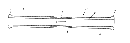
As can be seen from Fig. 1, the roll-back tube
construction according to the invention comprises a
roll-back tube 1 consisting of an inner tube section 2
~which is slidably guided through a drive and guide
sleeve or tube-guiding part 3, with an annular gap
forming between them, and is turned back in its front
,~rea (turn-back area) 4 to form a front outer tube
section 5. The front outer tube section 5 is in this
,-ase brought back to the drive and guide sleeve (tube-
guiding part) 3, which is made of a rigid material,
preferably a synthetic material or a metal, and is
Eastened at an axial end section on the drive sleeve 3
:in such a way that the latter comes to lie between the
:inner tube section 2 and front, outer tube section 5.
'rhat is to say, in other words, the end of the front,
outer tube section 5 is preferably bonded or vulcanized
CA 0223~643 1998-04-23
g
onto the outer jacket surface of the drive sleeve 3 in
an axial end area thexeof. Alternatively, another type
of fixing can be provided, for example a tube clamp or
the like.
In a rear area (turn-back area) 6 of the roll-
back tube 1, the inner tube section 2 is turned back to
form a rear outer tube section 7 which is likewise
brought back to the drive sleeve 3 and is fixed on an
axial end of the drive sleeve 3 in the same way as has
been described above. This axial end of the drive
sleeve 3 likewise comes to lie between the inner and
outer, rear tube sections 2 and 7. The drive sleeve 3
is used, on the one hand, as a guiding element for the
inner tube section 2, in order to prevent warps and the
formation of folds and creases, and, on the other hand,
as a connection piece for the front outer tube section
and the rear outer tllbe section 7, in which case a
central area of the drive sleeve 3 remains exposed on
its outer jacket surface, i.e. remains uncovered by the
roll-back tube 1. In this central section the drive
sleeve 3 has at least one opening 8, preferably a
longitudinal slot of predetermined width extending in
the axial direction. In the present case, four or more
longitudinal slots 8 are provided, arranged at a
uniform angular distan,-e from each other, of which two
diametrically opposite longitudinal slots are shown in
Fig. 1. In addition, the drive sleeve 3 preferably has,
on its inner side, a number of continuous longitudinal
grooves (not detailed) which open out at the end faces
of the drive sleeve 3 into cavities, which are formed
between the inner tube section 2 and the outer tube
,ections 5, 7. These longitudinal grooves can be run
either axially parallel or in a helical shape.
As can be seen in particular from Fig. 1, the
material, i.e. the type of material and strength of
material, of the roll-back tube 1 is chosen in such a
way that a bead-shaped widening forms in each case at
lhe front and rear roll-back area 4, 6 as a result of
an accumulation of material at the turn-back.
CA 0223~643 1998-04-23
-- 10 --
The type of the material and the strength of
the material in the preferred illustrative embodiment
of the invention are described in detail below with
reference to Figs. 2 and 3.
The roll-back tube 1 according to the preferred
illustrative embodiment is made of a silicone material
extrucded to form a tube 9, with a wall thickness of 0.5
to 1.5 mm, preferably 0.8 mm. This silicone tube is
surrounded by a reinforcement arrangement 10,
preferably made of nylon (hereinafter referred to as
the nylon winding or else as the wire winding), which
in turn is covered by a covering 11 of silicone. The
wall thickness of the covering 11 is in this case 0.1
to 0.5 mm, preferably 0.2 mm. The stiffening
arrangement 10 made of nylon is, as can be seen in
particular from Fig. 2, a nylon filament, or a nylon
spun to give a filament, which is wound in the axial
direction of the silicone tube 1 about its jacket
surface, with a pitch of 0.2 to 2 mm, preferably 0.5
mm, with a predetermined tensioning. The covering 11 of
silicone in this case fills the gaps (spaces) between
the individual nylon filaments of the reinforcement or
of the nylon winding 10 and in so doing covers the
reinforcement 10 completely on the outside. The above
statements in relation to the dimensions of the roll-
back tube and of the nylon winding refer to a roll-back
tube construction particularly for medical purposes,
for example for an endoscope shaft or a catheter. These
can, however, differ, particularly if the roll-back
tube construction is for examining and working in
conduits or shafts which cannot be accessed, or can
only be accessed with difficulty, in another way. In
addition, nylon as the material is only given as a
~ preferred illustrative embodiment, and it can readily
be replaced by anc,ther material having similar
properties. The properties of nylon can also be
simulated by constructional measures, as set out in
brief below.
CA 0223~643 1998-04-23
,- - 11 --
As has already been pointed out at the start,
the reinforcement 10 must permit a slight expansion of
the tube, so that the latter can be fitted. The spun
nylon filament which is used permits such a widening as
a result of its inherent elasticity. If, for example, a
wire winding is used, the wire must be run in a zigzag
formation, for example, in order to be able to be
slightly stretched elastically in the longitudinal
direction of the wire.
To produce the above-described roll-back tube
construction according to the preferred illustrative
embodiment, the following procedure is followed:
To produce the roll-back tube 1 per se, the
silicone tube 9 produced by extrusion is first drawn
elastically onto a metal rod or another circular
article (not detailed), the diameter of which
essentially corresponds to the internal diameter of the
silcone tube 9 or is slightly greater. Using a winding
machine ~not shown), lhe nylon filament or spun nylon
filament 10 is then wound on, the winding machine being
guided simultaneously around the silicone tube 9 at a
continuous speed of axial movement and the silicone
tube 9 being rotated. This produces a nylon filament
winding as reinforcement on the silicone tube 9, with a
pitch of the aforementioned 0.2 to 2 mm.
After the wind:ing procedure has been completed,
liquid silicone is applied radially and uniformly onto
the jacket surface of the silicone tube 9 and onto the
reinforcement 10, as a result of which the covering 11
of 0.1 to 0.5 mm wall thickness is formed. This
covering does not need to have the same wall thickness
at every point, but can vary in the longitudinal
direction of the tube. After the silicone has hardened,
the tube 9 is subjected to a vulcanization step in
order to obtain a sufficient bonding of the
silicone/nylon filament: laminate.
The roll-back tube 1, formed in the above
manner, is then shortened to a certain length of about
CA 0223~643 1998-04-23
- 12 -
2 to 3 m, and is guided through the externally
manufactured drive sleeve 3.
The roll-back tube 1 is thereafter turned back
outwards at its axial ends (roll-back areas 4, 6) and
guided back to the drive sleeve 3 to form the outer,
front and rear tube sections 5, 7. Finally, as is shown
in Fig. 1, the roll-back tube ends are bonded sealingly
or otherwise fixed on the outer face of the drive
sleeve 3, on the respective axial end sections thereof.
The drive sleeve 3 here serves for securing the
drive mechanism (not detailed) whose housing is clamped
on the drive sleeve 3 in such a way that the opposite
ends of the roll-back tube 1, fixed on the drive sleeve
3, come to lie between the drive sleeve 3 and the drive
mechanism and its housing almost in the manner of
seals. This drive mechanism has friction wheels
~likewise not shown) which, when the drive mechanism is
secured on the drive sleeve 3, protrude through the
slots 8 represented in Fig. 1. The endoscope shaft
(likewise not shown) or a shaft-like circular article,
such as, for example, ~ catheter, is finally introduced
into the roll-back tube 1, its diameter being slightly
smaller than the internal diameter of the inner tube
section 2 of the roll-back tube 1, and the friction
wheels press against the endoscope shaft (not shown)
via the inner tube sect:ion 2.
Trials conducted by the inventor on an
endoscopy apparatus have shown that, compared to a non-
reinforced roll-back tube made exclusively of silicone
or another material (e g. neoprene), the roll-back tube
1 with the above-described nylon winding 10 in addition
-o the guide sleeve 3, or with the above-described
constructional design of the roll-back tube 1, is able
lo transmit 3 times as-much shearing force in the axial
direction on the endoscope shaft before it shows a
lendency to crease formation. The roll-back behaviour
is influenced only slightly by the above-described
nylon winding 10, so that loss of efficiency, i.e. an
increase in the drivinq force required by the turn-back
CA 0223~643 l998-04-23
- 13 -
procedure during introduction of the endoscope, remains
minimal.
Finally, it should be noted that the
constructional design of the roll-back tube 1, in
particular the design of the reinforcement 10 according
to the invention, is not restricted to the roll-back
tube of the type which is rolled back at both ends. The
roll-back tube construction can also be advantageously
used on roll-back tubes rolled back at one end, in
which cases the rear turn-back area, which, according
to the above description, takes up a braking force
counter to the advancing force of the friction wheels
for synchronizing the advance speeds of the endoscope
shaft and of the ro:Ll-back tube, is replaced by a
further driving and braking mechanism which acts
exclusively on the endoscope shaft, independently of
the actual driving device, and therefore only a turn-
back in the front area of the roll-back tube is
necessary for the advance movement of the endoscope
shaft and of the roll-back tube.
Moreover, the invention is not limited to the
exclusive use of silicone as the material for the tube;
instead other materials having the same or similar
properties in respect of processing, flow behaviour and
elasticity, compatibility with the human body, reaction
with lubricants, etc , can also be used as base
material .
In summary, the invention thus relates to a
roll-back tube const]uction as transporting means,
preferably for a flexible endoscope shaft, with a
silicone roll-back tube consisting of the inner tube
section, which at least: at one turn-back area is turned
back to form the outer tube section, and which is
provided with a reinforcement. I~e reinforcement
consists of a nylon filament winding or a wire winding
with a pitch of 0.2 t~ 2 mm about the silicone tube,
which reinforcement is in turn surrounded by the
,ilicone covering. The roll-back tube construction is
designed in accordance with the type of tube which can
CA 0223~643 l998-04-23
~ - 14 -
be rolled back at both ends, where front and rear outer
tube sections are con:nected at one end by means of a
tube-guiding sleeve arranged between them, through
which the inner tube section extends. The tube-guiding
sleeve is used for mounting the roll-back tube drive.