Note: Descriptions are shown in the official language in which they were submitted.
CA 02235863 1998-04-24
STRUCTURAL PANEL AND CONNECTOR SYSTEM
The present invention relates to a building construction system and more
particularly to a structural panel and connector system that may be used to
provide
readily transported building kits for assembly into buildings quickly and
without highly
skilled personnel.
According to the present invention there is provided a construction
system for the erection of a building on a floor slab, the system comprising:
a plurality of structural wall panels having bottom edges, opposed side
edges and slots in the bottom and side edges;
bottom connector plates mountable on the floor slab to project upwardly
from the floor slab to engage in respective ones of the slots in the bottom
edges of the
panels; and
side connector plates engageable in aligned slots in adjacent side edges
of adjacent ones of the panels.
The bottom connector plates are readily mounted on the floor slab using
flanges and conventional fasteners, for example nails, screws or bolts. A wall
panel
may then be set on one or more bottom connector plates and fastened in place
using,
for example a nail or screw through the wall panel and the connector. Other
wall
panels are also supported on bottom connector plates and adjacent panels are
coupled using side connector plates that fit into the aligned side slots in
the panels.
The panels are connected to the side connector plates with fasteners extending
into
the panels and through the connector plates. The panels are pre-drilled to
accept the
fasteners or othenrvise marked to indicate the proper fastener locations.
The structural wall panels may be constructed as stud wall frames with
inner and outer skins of an appropriate sheet material and, where desired, an
insulated core. The selection of the frame structure will depend on the
structural
CA 02235863 1998-04-24
-2 -
requirements of the panel. The sheathing or skins of the panels are of
materials
suitable for the end use of the building. Drywall, wafer board, particle
board, plywood
and other materials are suitable for various applications.
The panels may be equipped with doors or windows, suitably framed.
Using this system, the basic structure of the building is set up by erection
of the walls.
The building may be completed with a set of roof trusses, roofing on the
trusses and
additional panels that extend from the taps of the structural panels to the
roof where
required.
In the accompanying drawings, which illustrate an exemplary embodiment
of the present invention and two embodiments of the side connector:
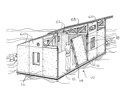
Figure 1 is a perspective view of a building being constructed according
to the present invention;
Figure 2 is a front view of two assembled panels with the skin omitted to
show the panel framework;
Figure 3 is an end view of Figure 2;
Figure 4 is a detail of the bottom of Figure 3;
Figure 5 is a front view of a side connector;
Figure 6 is an edge view of a side connector;
Figure 7 is a front view of a bottom connector;
Figure 8 is a side view of the connector of Figure 7;
Figure 9 is a top view of the connector of Figure 7 and 8;
Figure 10 is a front view of an alternative embodiment of side connector;
and
Figure 11 is a side view of the connector of Figure 10.
Referring to the accompanying drawings, particularly to Figure 1, there is
illustrated a building 10 being erected on a floor slab 12. Spaced around the
CA 02235863 1998-04-24
-3-
periphery of the floor slab are bottom connectors 14 that engage the bottom
edges of
structural wall panels 16. Adjacent panels have their side edges connected by
connector plates 18.
As illustrated most particularly in Figures 2, 3 and 4, each of the wall
panels 16 is constructed with an outer skin 20, an inner skin 22 and a
structural frame
24 of wooden studs. The frame includes a double top plate 26, a bottom plate
28 and
a set of studs 30 joining the top and bottom plates. In the panel illustrated
on the left
hand side in Figure 2, the left and centre studs 30 are single while the right
hand stud
is double. In the right hand panel, the studs along the side edges are both
double,
while the centre stud is single.
The configuration of the bottom connector 14 is illustrated most
particularly in Figures 7, 8 and 9. This connector includes a floor flange 32
with a
fastener hole 34 and an upright connector flange 36 projecting upwardly from
one end
of the floor flange. A fastener hole 38 is formed in the connector flange. As
illustrated
in Figures 1 through 4, the bottom connector is mounted on the floor slab 12
using a
fastener 39 through the fastener hole 34. To mount the wall panel on the
bottom
connector, slots 40 in the bottom plate 28 are placed over the upright
connector
flange 36. A fastener 41 is then driven into the bottom plate 28, through the
fastener
hole 38 in the connector flange. The panel is pre-drilled to receive the
fasteners.
Alignment of the fasteners with the holes in the connectors ensures proper
alignment
of the panels on the connectors.
As illustrated most particularly in Figures 5 and 6, the side connector
plates 18 are circular. They have four fastener holes 42 spaced along a
diameter of
the plate. A second diameter perpendicular to that through the fastener holes
is
marked by line 44 across the plate. In use, the side connector plate 18 is
inserted into
a slot 46 in the side edge of a wall panel until the line 44 lines up with the
side edge.
CA 02235863 1998-04-24
-4-
At that point the connector is fastened in place using fasteners through the
fastener
holes 42 and corresponding pre-drilled holes in the panel studs. When the next
adjacent panel is put in place, the connector plates 18 extend into the slots
46 in the
side edge of that panel and are fastened in place with fasteners through the
studs and
the fastener holes 42.
Figures 5 and 6 illustrate an alternative embodiment of the side connector
plates where the line 44 is omitted and a tab 48 is struck out between a cut
line 50 in
the plate and a radial fold line 52. The tab 48 lies flush on the edge of the
panel when
the connector is properly seated in the slot 46. A fastener hole 54 in the tab
48 is
used for fastening the connector to the edge of the panel.
Returning once more to Figure 1, erection of a building involves fastening
the bottom connectors 14 to the floor slab 12, installing a wall panel 16
which is set in
place on the bottom connectors and fastening the panel in place. Side
connectors 18
are inserted into slots 46 in the side edge of the panel and fastened in place
on the
mounted bottom connectors and then another panel is put in place edge-to-edge
with
the first, with its slots 46 engaging the side connectors 18 of the already
installed
panels. At comers of the building, where two walls meet, one of the panels
will
overlap the side edge of the other and be fastened in place using fasteners,
for
example nails, through the edge studs of the two walls.
Once the building walls are in place, a set of trusses 56 is mounted on the
walls to support roofing 58. To complete the building, panels 60 extending
from the
top of the outer skin of each panel 16 to the underside of the roof 58 are
fastened in
place over the trusses 56.
Once the building has been erected as described, it is finished by
installing services, partition walls, windows and doors as required.
While one embodiment of the invention has been described in the
CA 02235863 1998-04-24
foregoing, it is to be understood that other embodiments are possible and are
intended to be included herein. A wide variety of buildings can be constructed
using
the technique described above. Kits for manufacturing buildings according to
the
invention are easily packaged for shipping with very little waste space or
excess
weight.