Note: Descriptions are shown in the official language in which they were submitted.
CA 02236121 1998-04-29
MULTI-SHAFT SCREW-TYPE EXTRUDER, IN PARTICULAR TWIN-
SHAFT EXTRUDER
BACKGROUND OF THE INVENTION
Field of the Invention
The invention relates to a multi-shaft screw-type extruder and in particular
to a twin-shaft extruder.
Background Art
A screw-type extruder according to the prior art is known from DE
25 50 969 C2. It is provided with kne~ling disks which are non-rotatably
15 mounted on the two screw shafts, providing for a proces~ing of the material
conveyed through the extruder, for instance homogeni7ing mixing, knead-
ing, plasticizing and the like. Depending on the number of their flights, the
kneading disks may have a lenticular (two-flight kne~ling disk), trochoidal
(three-flight kneading disk) etc. contour.
The mentioned prior art patent shows three-flight kne~ling disks, the crest
portions of which are re~ ce~l as colnl)~ed to the basic width of the
kneading disk for mixing-and-scraping-studs to form on the periphery.
25 In addition to the mixing function as a result of the intermeshing action of
the kneading disks which are disposed side by side in a joint axial position,
these studs serve for scraping the material to be processed off the inside
wall of the casing. To this end, the faying surfaces of the studs which ex-
CA 02236121 1998-04-29
- 2 -
tend radially outwards and are disposed by defined play towards the inside
wall of the casing, slide over the inside wall of the casing, taking along the
accllm~ ted material.
5 A drawback of the known construction resides in that the casing wall is
scraped only where the crest portion of the mixing-and-scraping-studs is
fully developed, scraping not taking place in the area between these studs.
This faulty scraping effect leads to considerable deterioration of the heat
transfer from and to the casing wall, because the processed product is not
10 exchanged in the areas that are not scraped. Furthermore, heat transfer by
convection does not take place, owing to the bad thermal conductivity con-
ditioned by the product. Also, these problems entail the risk that the mate-
rial which has not be scraped off will scorch on the inside wall of the cas-
ing, which will result in the product being damaged by reason of the ensu-
15 ing prolonged dwell times of the product in these areas. Furthermore, thetechnological properties of the screw-type extruder are negatively affected
by the casing cross-section becoming gradually clogged.
DE 41 22 912 Al te~ches a twin-screw extruder in which the faying sur-
20 faces of the kne~rling disks which extend in the peripheral direction are
provided with edges which are transverse to the axial direction of the
screws and which at least partially slope relative to the axis of the screws.
The d~mming effect of the kneading disks is m~int~ined by this sloping, but
their free cross-sectional passage area is enlarged to such an extent that
25 shear peaks that might be thermally harmful to the product to be processed
are clearly red~lGed However, the embodiment illustrated by
DE 41 22 912 Al does not ensure either that the full surface of the inside
wall of the casing is scraped.
CA 02236121 1998-04-29
SUMMARY OF THE INVENTION
It is the object of the invention to specify an arrangement of the mixing-
5 and-scraping-studs in which scraping of the entire surface of the inside wall
of the casing is attained, accompanied with the m~ e.~ ce of the advan-
tages in terms of processing technology of these studs of red~lced width.
According to the invention, this object is attained in a screw-type extruder
10 comprising a casing; several, prefe~ably two, parallel and partially inter-
secting casing bores; several, preferably two, shafts disposed in the casing
bores and plerel~bly drivable to rotate in the same direction; screw ele-
ments non-rotatably mounted on the shafts; and intermeshing kne~(ling
disks, which are non-rotatably mounted on the shafts and the respective
15 crest portions of which are reduced in relation to the disk width for mixing- and-scraping-studs to form, which are located on the periphery; wherein
the mixing-and-scraping-studs on each kne~l1ing disk are mi~li~ed in the
axial direction such that peripheral faying surfaces jointly cover the entire
disk width. Thus, the m~tçri~l resting on the casing wall is removed in a
20 single operation upon a full rotation of the kn~-ling disk over its width at
each axial position. The prior art dlawbacks mentioned at the outset are
efficiently avoided. Thus, an excellent mixing effect of these kneading
disks is accompanied with complete scraping of the casing wall.
25 Further features, details and advantages of the invention will become ap-
parent from the ensuing description of prerelled embodiments, taken in
conjunction with the drawing.
CA 02236121 1998-04-29
BRIEF DESCRIPTION OF THE DRAWING
Fig. 1 is a plan view of a twin-shaft extruder with a casing in an il-
lustration partially broken open;
s
Fig. 2 is a diagli~."~ tic section through the extruder on the section
line II-II of Fig. l;
Fig. 3 is a plan view of a kneading disk in a first embodiment;
Fig. 4 is a lateral view in the axial direction of a kneading disk in a
second embodiment;
Fig. 5 is a plan view of the kneading disk of Fig. 4;
Fig. 6 to 8 are partial sections of the kneading disk on the section line
VII-VII of Fig. 5 with di~ling embo~liment~ of the bottom of
the clearance;
~0 Fig. 9 and 10 are sections, analogous to Fig. 1, of a screw-type extruder
with kneading disks in two further embodiments; and
Fig. 11 is a plan view of one of the kne~ling disks of Fig. 10.
25 DESCRIPTION OF THE PREFERRED EMBODIMENTS
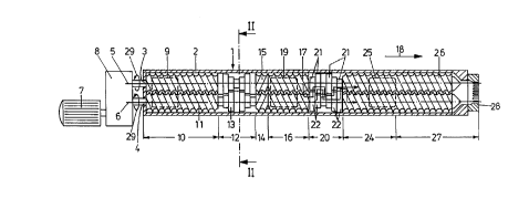
Fig. 1 illustrates a twin-shaft extruder 1 with its casing 2 in an illustration
broken open. The twin-shaft ex~uder 1 comprises two shafts 3, 4, the axes
CA 02236121 1998-04-29
5, 6 of which are parallel. A motor 7 drives the shafts 3, 4 in the same di-
rection of rotation 29 by way of a branching gearing 8. Adjoining the
gearing 8, a charging hopper 9 (roughly oudined) is provided in dhe casing
2 for a polymer to be melted in dhe extruder 1. Subsequent to and below
5 this hopper 9, a feed zone 10 is formed, in which conveying screw ele-
ments 11 are disposed on the shafts 3, 4. Subsequent to this, knea(ling disks
13 are non-rotatably mounted on the shafts 3, 4 in a melting zone 12. This
is followed by an ~ccllmlllation zone 14, in which the shafts 3, 4 are pro-
vided with return conveying screw elements 15, the threads of which hav-
10 ing a direction reverse to that of the conveying screw elements 11. The ac-
cllmlllation zone 14 is followed by an adding zone 16, in which again con-
veying screw elements 17 are mounted on the shafts 3, 4, feeding in the
conveying direction 18 ofthe extruder 1. Directly behind dhe return con-
veying screw elements 15, an adding hopper 19 (roughly outlined) opens
15 into dhe casing 2. It serves for the addition of additives such as fillers or glass fibers into the melt.
The melting zone 16 is followed by a mixin~ zone 20, in which dhe shafts
3, 4 are provided widh mixinp and shearing elements 21, 22. These are
20 preferably kneading disks 13 according to dhe invention, details of which
will be explained in dhe following. This mixing zone 20 is followed by a
vented zone 24, in which a vent 25 (roughly oudined) is formed in the
casing 2. In this vented zone 24 conveying screw elements 26 are mounted
on dhe shafts 3, 4, conveying the polymer, to which fillers and reinforcing
25 agents have been added, in the conveying direction 18 towards a discharge
zone 27 widh a so-called apertured strip as a discharge member 28.
CA 02236121 1998-04-29
As regards the positioning of the kneading disks 13 and the mixin~ and
shearing elements 21, 22 according to the invention, they are prererably
used where a gentle mixin~ and shearing effect is required for the process
in the screw-type extruder. These are for instance zones where the product
5 itself must be transferred into a homogeneous form in terms of molecular-
weight distribution, melt index or temperature. Depending on the require-
ments, the mixing and shearing elements (21, 22, kneading disks 13) can be
employed virtually at any place in the screw-type extruder, it being possi-
ble to select embodiments of the element that correspond to the conditions
10 in the process and the properties of the product.
The design of the kneading disks 13 is explained, based on Figs. 2 and 3 .
They are non-rotatably placed in pairs side by side in an axial position on
the shafts 3,4, the successive kneading disks 13 on a shaft 3 and 4, respec-
15 tively, being displaced relative to each other, from one pair to the next, by adefined angle of for instance 30~, 45~ or 60~. Since this is customary in
extruders, Fig. 2 illustrates only one pair of kn~(ling disks 13.
These kne~ling disks 13 are two-flight kne~tlin~ disks, in an axial view
20 having a subst~nti~lly lenticular contour. As co~ ared to the width B of the
disk the radially outward crest portions 30, 30' are reduced by shoulders 31
that stand back radially. Mixing-and-scraping-studs 32, 32' are formed in
this way, which are located on the periphery. These studs 32, 32' are axi-
ally mi~ Qned on each kneading disk in such a way that their peripheral
25 faying surfaces 33 jointly cover the entire width B of the disks. This pro-
vides for the extruder-processed material to be scraped off the casing inside
wall 34, which is formed by the casing bores 42, 43, over the full surface
CA 02236121 1998-04-29
in the vicinity of the melting zone 12 per complete rotation of the shaft 3
and 4.
As seen in Fig. 3, the two opposed studs 32, 32' are displaced by a mis-
S ~lignmPnt V to such an extent that the fronts 35, turned away from each
other, of the studs 32, 32' are flush with the respective fronts 36 of the
kne~ling disk 13. Moreover, the effect of complete scraping of the casing
inside wall 34 is attained in particular when the total width of the disk
shoulders 31 in a crest portion (30) amounts to half the disk width B maxi-
10 mally.
In the embodiment of a kneading disk 13 seen in Figs. 4 and 5, a mixing-
and-scraping-stud 32 is formed in a crest portion 30 (bottom of Figs. 4 and
5), which, in relation to the disk width B, is narrowed on both sides by
15 shoulders 31. Two studs 32' are disposed by displacement thereto in the
second crest portion 30 (top of Figs. 4 and 5), their fronts 35 again lying in
a plane with the fronts 36 of the kne~(ling disk 13. The two studs 32' form a
shear clearance 37 between them, which overlaps the opposite mixing-and-
scraping-stud 32, referred to the axial direction. The faying surfaces 33 of
20 the three studs 32, 32' again jointly cover the entire disk width B so that the
material is completely scraped off the casing inside wall.
The embodiment, seen in Figs. 4 and 5, of the kneading disks 13 advanta-
geously serves to attain a shearing and mixing effect on the material to be
25 processed, this being accompanied with simlllt~neous scraping of the cas-
ing wall.
CA 02236121 1998-04-29
- 8 -
Depending on the requirements in terms of process technology, the shear
clearance 37 may be embodied dirrelenlly as seen in Figs. 6 to 8. In the
embodiment seen in Fig. 6, the contour of the bottom 38 of the clearance is
formed as an arc of a circle concentric to the axis 5 of the shaft 3 and hav-
5 ing the radius R. This results in a depth, uniform in the peripheral direction,of the shear clearance 37. As with all the other embo~liment~ of the knead-
ing disks, the basic profile of the kne~lin~ disk may also be disposed ec-
centrically to the shaft axis, which is the case in the en~lling illustrations.
10 In the embodiment seen in Fig. 7, the bottom 38 of the shear clearance
possesses a contour which ascends counter to the direction of rotation 29 of
the shaft 3 and which forms an arc of a circle eccentric relative to the shaft
axis 5 and having the radius R'.
15 In Fig. 8, the bottom 38 of the clearance is provided with a contour deviat-
ing from that of an arc of a circle.
Fig. 9 illustrates another alternative embodiment of the kneading disks 13,
~ in which the bottom of the clearance is embodied according to the laws
20 known per se for a so-called self-cleaning faying profile for a multi-shaft
screw-type extruder with screw shafts rotating in the same direction. To
this end, a radially reduced shoulder 31 in the crest portion 30 of the left
kne~(lin~ disk 13L (length CD) is associated with a counter-convexity 39R
on the right knea~lin~ disk 13R (length C'A'). The peripheral surface of the
25 counter-convexity 39R slides over the peripheral surface of the shoulder
31, having the customary play, so that mutual scraping of the kneading
disks 13 and thus self-cleaning take place. In like manner, the left kneatling
disk 13L possesses a counter-convexity 39L (length AC) which cooperates
CA 02236121 1998-04-29
in the way specified with the reduced shoulder 3 lR of the crest portion 30
of the right kn.o~-ling disk 13R.
The flanks 40 (lengths BD and B'D', respectively) opposite the counter-5 convexities 39 have a contour which stands out less far in the radial direc-
tion and which cooperates with the faying surface 33 (length AB and A'B',
respectively) of the ~ltern~tçly opposite kneading disk 13.
In the kneading disk combination seen in Fig. 9, self-cleaning of the profile
10 is attained in addition to the scraping of the casing wall by a correction of the contour.
The same effect may be obtained in a different way by the contour seen in
Figs. 10 and 11 of kneading disks 13. Again, provision is made for a design
15 with mixing-and-scraping-studs 32 and an opposite shear clearance 37. The
faying sllrf~ce 33 of the stud 32 and the bottom 38 of the shear clearance
37 are jointly produced by a circular contour, which is illustrated by the
hatched circular areas in Fig. 10. The diameter 2R of this circular contour
corresponds to the dist~nce _ of the two axes 5, 6 of the extruder 1. Their
20 eccentricity e is ~lesi~ed such that the vertex 41 of the faying surface 33
scrapes the casing inside wall 34. The shear clearance 37 is defined by two
studs 32' that exhibit a contour in the shape of an arc of a circle. This arc ofa circle is adjoined in each case by an al)ploxi",~tely parabolic contour
which forms the shoulders 31 on both sides of the mixing-and-scraping-
25 stud 32. Self-cleaning of the profile is attained by the altern~ting engage-
ment of the stud 32 of one kneading disk 13L with the shear clearance 37
of the other kneading disk 13R. The mis~lignment of the studs 32 and 32'
again serves to achieve that the casing inside wall 34 is scraped over ~e
CA 02236121 1998-04-29
- 10-
complete width B of the disk upon one full rotation of the knea-ling disks
13.
Attention is drawn to the fact that the above exemplary embodiments illus-
5 trate single-flight kneading disks. By multiplication of the corresponding
knctulin~ disk contours, the kneading disks can also be embodied as being
multi-flight disks.
Further, several kneading disks of varying design as shown above and of
10 ch~n~ing angles of mi~lignment can be combined in a mixin~ zone.