Note: Descriptions are shown in the official language in which they were submitted.
1 , CA 022362~3 1998-04-27
.
NAVIGATION DEVICE HAVING A VIEWER FOR SUPERIMPOSING
BEARING, GPS POSITION AND INDEXED MAP INFORMATION
BACKGROUND OF THE INVENTION
The present invention relates generally to
navigation aids. More particularly, it concerns a
viewing device which allows one to superimpose a Global
Positioning System (GPS) location onto a transparent map
image.
The prior art teaches devices which use map
transparencies mounted in a frame with a lens and a
rotatable grid to facilitate map bearing. Such a device
is shown, for example, in U.S. Patent No. 3,094,781 to
Vangor and U.S. Patent Nos. 5,060,390 and 5,339,528 to
Hill. However, these devices do not integrate the actual
position of the viewer based on GPS data, with map
information to help eliminate navigation error for
amateur navigators.
SUMMARY OF THE INVENTION
The present invention is realized by a navigation
device comprising a case having a first end for viewing
and a viewing axis. The viewer includes a GPS sensor, a
microprocessor which receives input from the GPS sensor,
a transparent display mounted transverse to the viewing
axis in the navigation device and driven by the
microprocessor, and a battery powering the navigation
device. A map slide comprising a transparent map of a
predetermined geographical area is inserted into the
case, parallel to the transparent electronic display.
This allows one of the display and the map film to be
superimposed on the other, when viewed from the viewing
end of the case. The map slide is also provided with an
map memory which stores information about the extent of
the corresponding geographical area. When the map slide
is inserted into the navigation device, the
microprocessor reads the map memory and determines
~ , CA 022362~3 1998-04-27
whether the current position of the viewer is within the
extent of the map- If so, the microprocessor causes a
cursor to be indicated at a corresponding position on the
display so that a viewer can see the position of the
cursor relative to the map.
Another feature of the present invention is a
magnetic compass positioned at a second end of the case,
the display and the map slide being positioned between
the first and second ends. As the display and the map
slide are transparent, one can see the compass needle
from the viewing end. This allows a user to orient
herself relative to magnetic north, when viewing the map.
Yet another feature of the present invention is that
the map memory can also include information such as
waypoints and routes to be displayed on the transparent
display, and viewed at the same time as the map. The
waypoints and routes can be written into the map memory
by a personal computer, or the like. This can be done
either at the time the extent of the map is written into
the electronically, or subsequent thereto.
BRIEF DESCRIPTION OF THE DRAWINGS
These and other features, aspects, and advantages of
the present invention can be seen in the drawings in
which:
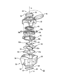
Fig. 1 shows an exploded view of a navigation device
in accordance with the present invention.
Fig. 2 presents the logic board of the control unit
used in the device of Fig. 1.
Fig. 3 shows a map slide in accordance with the
present invention.
DESCRIPTION OF THE PREFERRED EMBODIMENT
The contents of U.S. Patent Nos. 5,060,390 and
5,339,528 are incorporated by reference, to the extent
necessary to understand the present invention.
Fig. 1 shows an exploded view of a navigation device
20 in accordance with the present invention. The
--2--
. , CA 022362~3 1998-04-27
.
navigation device 20 has a viewing axis A which extends
from a first end 22 of the device to a second end 24
thereof. A lens 26 is positioned at the first end 22 of
the device and connected thereto by a rubber eyepiece 28.
Both the lens 26 and rubber eyepiece 28 are mounted in a
lower casing 30 of the navigation device 20. When the
device 20 is being used, a viewer looks through lens 26
down the viewing axis A.
Upper casing 32 is removably fastened to lower
casing 30. Attached to the upper casing 32, at the
second end 24 of the device 20 is a compass 34 having a
compass needle 36 rotatably mounted on a pin. The
compass 34 is provided with transparent upper and lower
faces so as to permit light to pass therethrough. This
allows one to view the compass 34 through the lens 26
when the device 20 is being used. A "North" marking or
equivalent indicator is provided on the upper face of
compass 34 so that it may be viewed when the navigation
device 20 is inverted.
A grid wheel 38 and a direction wheel 40, both with
transparent centers, are housed in the upper casing 32
below the compass 34. The wheels rotate in a controlled
fashion using geared teeth and small gears 38a spaced in
fixed positions between the wheels 38, 40 and around
their circumference. The grid wheel 38 is inscribed with
parallel grid lines and a first directional arrow aligned
parallel to the grid lines. Meanwhile, the direction
wheel 40 is inscribed with a second directional arrow.
The first and second directional arrows align with each
other when pointing at the "North" marking. The two
wheels are arranged such that rotation of one wheel in a
first direction causes counter-rotation of the second
wheel in a second direction. The grid wheel 38 is
retained by flange 42. Thus far, the description of a
device in accordance with the present invention is
similar to that in the aforementioned patents, which have
been incorporated by reference.
CA 022362~3 1998-04-27
The device of the present invention includes a slide
holder 50 positioned substantially transverse to the
viewing axis A and in the line of sight, at the upper end
of the lower casing 30. Slide holder 50 is arranged to
receive a map slide 52 which is inserted thereinto.
As shown in Fig. 3, the map slide 52 comprises a
slide frame 53 provided with a map memory 52a and a
transparent map image 52b. Slide holder 50 is equipped
with an electrical connector 50a to interface the map
memory 52a with other components of the device 20.
The map memory 52a is preferably implemented as an
electronically erasable programmable read-only memory
(EEPROM) 52a, although a simple PROM or EPROM may be
used, if the user is not expected to erase and write to
the map memory. The map memory 52a stores, among other
things, information about the map, such as the
geographical extent of the map contained on the map slide
52. The map memory 52a may also include user-specified
data such as waypoints and routes on that map. The map
memory 52a is electrically connected, via printed
conductors, to the electrical connector 50a of the slide
holder 50.
The transparent map image 52b is typically a color
transparency or film which depicts a map of an area of a
predetermined geographical extent. The transparent map
image 52b can be derived from a raster scanned image
created from either a photographic or digitized aerial
image, or may even be vectorized image. In addition to
the image, the transparent map image 52b may also show an
arrow 52c or other symbol indicating true north. In
general, there is no electrical connection between the
map image 52b and the map memory 52a.
Positioned between the slide holder 50 and the lens
26, at a distance from the lens which approximates the
lens' focal length, is a transparent electronic display
54 retained by a display holder 55. In the preferred
embodiment, the display 54 is a field effect twisted
nematic liquid crystal display (LCD), of the sort
.
CA 022362~3 1998-04-27
available from DCI, Inc. of Olathe, Kansas, and having
200 x 200 pixels in an area of 2.0" square.
Attached to the lower casing 30 is a control unit 56
which directs the electronic operation of the navigation
5 device. The control unit 56 is connected to the slide
holder connector 50a of the slide holder 50 by a first
ribbon cable, or equivalent (not shown). The control
unit 56 is also connected to a display connector 54a of
the display 54 by a second ribbon cable, or equivalent
10 (also not shown).
Attached to lower casing 30 is a battery pack 58
which supplies power to the remainder of navigation
device 20. In the preferred embodiment, battery pack 58
comprises four AA batteries.
Fig. 2 shows a block diagram of the various
components making up the control unit 56. Within the
control unit 56 is a logic board 60. Preferably, the
logic board 60 is encased in aluminum case for EMI
protection and also for improved ruggedness and
20 structural reinforcement. In the preferred embodiment,
the dimensions of the logic board 60 are 2.5" x 3.5" x
0.5". The logic board 60 includes a GPS chip set 62, a
microprocessor 64 and an LCD controller 66, which
typically comprises an LCD driver and associated
25 interface logic, as is known to those skilled in the art
of GPS system design.
The microprocessor 64, in the preferred embodiment
is a 68HC11 microcontroller, available from Motorola.
The microprocessor is provided with a local memory 65
30 which may comprise both read-write and read--only
portions.
The GPS chip set 62 is a commercially available
system provided by such vendors as Motorola, Rockwell or
Philips. As is known to those skilled in the art, the
35 GPS chip set 62 typically includes a GPS radio frequency
(RF) chip 70, a GPS filter 71 and an GPS correlator 72.
The output of the GPS correlator 72 is presented to the
CA 022362~3 1998-04-27
microprocessor 64 which processes information reflective
of the position of the device.
The GPS RF receiver 70 is electrically connected to
the disk-shaped GPS micropatch antenna 74 via a GPS
antenna connector 76 on the logic board 60. A flexible
cable (not shown) connects the GPS antenna 74 to the
antenna connector 76. As shown in Fig. 1, the GPS
antenna 74 is mounted flush over the compass at the top
end 24 of the upper casing 32 and is hingedly attached
thereto. Thus, the GPS antenna is movable from the open
position of Fig. 1, when the device 20 is being used, to
a closed position. When the GPS antenna 74 is in the
open position, light passes through the compass 34, as
discussed above. At nighttime, a user may direct a
flashlight at the top end 24 to help illuminate the
compass 34, the map image 52b and the display 54.
Alternatively, a light emitting diode 57, placed on the
slide holder, the display holder or some other component,
and turned on each time that switch 90 is activated, may
be used for illumination.
A map slide connector 80 is also provided on the
logic board 60. The map slide connector 80 is connected
by a ribbon cable, or equivalent, to the slide holder
connector 50a on the slide holder 50 which carries the
map slide 52 having map memory 52a. Alternatively, the
map slide connector 80 can be a female (or a male)
connector which mates with a complementary member on the
slide holder connector 50a. The microprocessor 64 reads
the map memory 52a via the map slide connector 80. This
allows information in the map memory 52a to be accessed
by the microprocessor 64 for subsequent processing and
calculations, and also for ultimate presentation on the
display 54.
An LCD connector 82 is also provided on the logic
board 60. The LCD connector 82 is connected by a
flexible ribbon cable, or equivalent, to the display
connector 54a which is provided on the display holder 55,
and provides a connection to the display 54.
. CA 022362~3 1998-04-27
The microprocessor 64 reads map information stored
in the map memory 52a. This information typically will
include the geographical extent of the map, such as the
latitudes and longitudes delimiting its extent. This
type of information, which is invariant for a given map
image 52b is provided at the time the map slide 52 is
created. Thus, when purchased by a user, the map slide
52 will already have the information representing the
geographical extent of the map image 52b.
The microprocessor 64 uses the information
representative of the geographical extent of the map, and
integrates it with the GPS information which gives the
user's current position. If the current position is
within the geographical extent of the map image 52b, the
microprocessor 64 outputs a first signal to the LCD
controller. The first signal causes a blinking cursor,
or other indicator, to appear on the display 54. As the
display 54 is in the line of sight of the map image 52b,
a viewer looking through the lens 26 sees the cursor
superimposed on the map, with the cursor indicating the
viewer's current position relative to the map image 52b.
As the user moves within the geographical extent of the
map, the cursor position is updated in a corresponding
fashion.
If, on the other hand, the user's current position
is not within the geographical extent of the map image
52b, the microprocessor 64 will output a second signal
which causes the display 54 to indicate that the map
image 52b does not contain the current location. For
instance, the microprocessor 64 may cause the latitude
and longitude, as sensed by the GPS system, to be written
in alphanumeric characters on the display. In addition,
or even in the alternative, an indicator light, such as a
red light emitting diode (LED) positioned next to the
LCD, but still within the line of sight, may be used to
signify that the map image 52b does not include the
current position. Regardless of how this is signified,
the user is thereby notified that she should insert the
CA 022362~3 1998-04-27
correct map slide 52 which includes the current position.
In the preferred embodiment, a portion of map memory
52a may be written to by a user. Thus, in addition to
the geographical extent of the map image 52b, the map
memory 52a may also have limited space devoted to user-
specified data, such as waypoints and routes. This
information may be loaded by the user into the map memory
52a, by means of a personal computer or the like. For
this, the present invention contemplates an adaptor
connectable to a serial port of the personal computer,
and into which a map slide 52 may be inserted. A
software program resident on the personal computer reads
the contents of the map memory 52a and displays it on a
screen. The user is allowed to interactively add, change
or delete information stored on the map memory 52a. This
information may include waypoints for subsequent display,
or even routes previously traveled. Once the user has
completed making these changes, at least a portion of the
map memory 52a is overwritten with the new information.
Normally, however, the information representing the
geographical extent of the map image 52b is not
rewritten.
During use, when user-specified data is stored on
the map memory 52a, and the current position is within
the geographical extent of the map image 52b, the
microprocessor 64 may also output additional signals to
the LCD controller to write the user-specified data onto
the display. In such case, then, the display 54 will
show the cursor indicating the user's current position,
in addition to the waypoints, routes and other user-
specified data, superimposed on the relevant map.
Operation of the navigation device is now described.
A user inserts the map slide corresponding to the
intended area of travel and activates the GPS capability
by pushing an ON/OFF switch 90 placed on lower casing 30.
The antenna 74 is opened and the device is raised into
the viewing position. The cursor appears on the display
CA 022362~3 1998-04-27
54 in approximately 30 seconds, which is the typical time
required to obtain a GPS position fix from a cold start.
The cursor represents the user's position to within
approximately 30-50 yards, given current civilian GPS
receivers. The user then rotates the grid and direction
wheels to establish the bearing to the user's planned
destination, as described in the aforementioned patents.
The user then flips the device over and the compass
needle is aligned with the North marking on the case.
Once this has been done, the second directional arrow
indicates the bearing to be taken.
The present invention provides a number of benefits
in the field of portable navigation devices. For
instance, a device in accordance with the present
invention accurately displays a user's position on a
color map or other image such as an aerial photo, a
satellite image or a vector map. The navigation device
also allows a user, such as a hiker, to establish an
accurate bearing or route to a destination without the
need for additional navigation tools or devices. The
device is long-lasting in the field, as it may be
operated intermittently to conserve battery power. A
device in accordance with the present invention is easy
to use, and requires little, if any, training, in
navigation, as one's current position and one's
destination can be seen by viewing the display
superimposed on the map. Finally, the electronic memory
of the present invention permits a user to store a
planned route to facilitate a journey.
While the present invention has been disclosed with
reference to certain preferred embodiments, these should
not be considered to limit the present invention. One
skilled in the art will readily recognize that variations
of these embodiments are possible, each falling within
the scope of the invention, as set ~orth in the claims
below.