Note: Descriptions are shown in the official language in which they were submitted.
CA 02236326 1998-04-29
DOCUMENT WITH A MOIRE-GENERATING RASTER STRUCTURE
The present invention relates to a data carrier, in par-
tic~ular document of value, with at least one halftone image
represented by structural elements, each structural element
having a basic geometry and a size whereby the size of the
structural element represents a gray level of the halftone
image, and to a method for producing the same. The invention
further relates to a data carrier, in particular document of
value, with at least one picture element represented by one
or more structural elements.
A special problem with documerLts, such as documents of
va]ue, is the protection from forgery, in particular by copy-
inq or scanning an authentic document to produce a falsified
document. For example, EP 0 710 574 A2 relates to a security
docurLent with a drawing whereby a moiré pattern arises in the
correspondirlg drawing on a copy of the security document. For
this purpose a whole-area screen structure with parallel
lines is provided. ~he drawing is done in the form of a half-
tone image, the thicknesses of the lines being varied in a
contact screen structure as described in EP 0 085 066 B1.
Fur~her, the distance between the lines is varied over the
ent:ire halftone image in accordance with a modulation func-
tion. That is, the number of lines per unit length varies
over the total surface of the drawing. Modification of such a
line density leads to copy protection against color copiers
or scanners since the superimposition of the screen structure
at least in a predetermir;ed area with the scanning screen of
the copier or scanner produces a very striking moiré pattern.
Since this moiré pattern can be seen only on the copy, not on
the original, the copy is easily identifiable as a forgery.
Although there is a moiré effect at least in predeter-
mirled areas through the variation of line density everL with
different scanning screens of the scanner, the variation of
line density over the total surface of the drawing has an ex-
CA 02236326 1998-04-29
- 2 -
tremel~ adverse effect on the optical appearance of the half-
tone image. The alternation between high and low density or
nu~ber of lines per unit area causes the picture to seem
restless and inhomogeneous and the screen pattern to dominate
the halftone image rather than vice versa, so that the pic-
ture is not very appealing esthetically.
The present invention is therefore based on the problem
of providing a document with a moiré-producing structure, in
particular on a halftone image, whereby large-surface moiré
structures are produced upon copying of the document for de-
tecting forgeries, the moiré-producing structure simultane-
ously fitting homogeneously into the halftone image and re-
ceding as a background structure relative to the halftone im-
age itself.
This problem is solved in a document of the aforemen-
tioned kind by the characterizing features of the independent
cl~ims.
The invention is based on the idea of dividing the total
surface of a picture in which moiré structures are to be pro-
du,-ed upon copying into a plurality of areas. Each area has
associated therewith a number of structural elements for pro-
du-ing the gray levels present in this area. The number of
s.ructural elements is selected in at least two contiguous
areas so as to be different in the two contiguous areas. This
different number results necessarily in an offset of the
structural elements relative to the structural element of the
adjacent area. Thus, the halftone image applied to the data
carrier is divided into areas which have different screen
frequencies. Upon an attempt to copy this halftone image or
read it into a data processing system with a scanner, the
scanning frequency of the scanner or copier is superimposed
with the applied, different screen frequencies of the halr-
tcne image. This superimpos tion leads to disturbances in the
reproduction of the halftone image, this disturbance being
apparent in particular in the production of a large-surface
mc~ire pattern.
CA 02236326 1998-04-29
- 3 -
The variation of the number of structural elements in
the areas of the halftone image produces a different screen
frequency for each area, thereby ensuring that a moiré pat-
tern arises even when the scanning screen, i.e. the scanning
or copying frequency, is varied. This then appears in the ar-
ea, of the total surface for which the scanning and screen
frequencies are coordinated with each other such that a moiré
pattern can arise.
According to the invention the image thus has predeter-
mined areas each having a predetermined number of structural
ellments, the number of structural elements per unit area of
an area being different between at least two contiguous areas
and/or the structural elements being offset from each other
in at least two of the areas. This has the advantage that
disturbances such as moiré patterns arise even with different
sc~nning screens, for example of a copier or scanner, without
inhomogeneities arising in the total surface screen, in par-
ticular in the halftone image.
In a preferred embodiment the structural elements of an
area of the halftone image have a uniform basic geometry, it
being particularly preferable for the structural elements of
all areas to have a uniform basic geometry. The structural
elements are preferably executed as lines, a predetermined
thickness of a line representing a predetermined gray tone
separately for each area. This makes it possible to ensure a
homogeneous brightness level over the total gray-level image
despite the gray-level image being divided into a plurality
of areas with different numbers of structural elements. If
for example n structural elements are present in a first area
and n + 10 structural elements in the adjacent area, the sec-
ond area would appear optically darker than the first area
sclely due to the increased number of structural elements.
This difficulty is avoided if a given width of the line cor-
r~sponds tc a given gray tone within one area, while a dif-
ferent, for example smaller, width of the line is provided
CA 02236326 1998-04-29
for the same given gray tone within a second area having a
higher number of lines in this case.
The inventive representation of halftone images by areas
wit:h different numbers of structural elements thus achieves
the advantage that the halftone image has different screen
frequencies which are superimposed with the scanning fre-
quency of a scanner or copier used for scanning the document,
and the different screen frequencies produced by the varied
number of structural elements per area offer the possibility
of superimposing the scanning frequencies with a plurality of
screen frequencies, thereby clearly increasing the probabil-
ity of a mo:iré pattern forming. Simultaneously the effect of
individual areas darkening due to the increased number of
structural elements is avoided since the predetermined size
of the structural elements corresponds to a predetermined
gray tone within an area, but the predetermined sizes of the
structural elements in the different areas can represent dif-
ferent gray tones depending on the number of structural ele-
ments in each area.
Further features, advantages and preferred embodiments
of the present invention can be found in the subclaims and
the following description of the figures, in which:
Fig. 1 shows an enlarged representation of a halftone
imaye with a moiré-producing structure according to a first
embodiment of the present invention,
Figs. 2a to 2d show several attempted copies of the in-
ventive halftone image of Fig. 1,
Fig. 3 shows an enlarged representation of a halftone
image with a moiré-producing structure according to a second
embodiment of the present invention,
~ igs. 4a to 4b show two attempted copies of the inven-
tive halftone image of Fig. 3, and
Fig. 5 shows an en]arged representation of two struc-
tural elements shown accordirg to a third advantageous em-
bodiment of the present invention.
CA 02236326 1998-04-29
-- 5 --
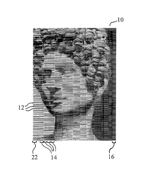
Fig. 1 shows an enlarged detail rendition of a portrait
represented according to the present invention as a halftone
image with a moiré-producing structure. Halftone image 10 is
divided into different column-like strips 14, 16, 22 each
having a nu~er of structural elements 12. In the present em-
bodiment there are 23 strips, whereby this number can also be
selected higher or lower. Each strip 14, 16, 22 has associ-
ated therewith a number of linear structural elements 12
forming a screen structure in each column. Halftone image 10
is represent:ed by linear structural elements 12, a certain
line thickness corresponding to a certain gray tone of half-
I tone image 10 in each area.
Within column or strip 14, 16, 22 vertical linear struc-
tural elements 12 can vary in their screen width and/or angu-
lar position and/or modulation.
Each slrip 14, 16, 22 contains a predetermined number of
structural elements 12, i.e. a predetermined number of lines
based on the total portrait height. The line density is for
example 20 :lines per cm in first strip 16. First strip 16
comprises 118 lines in the shown embodiment. This number of
lines increases from strip to strip so that last strip 22 is
present with 171 lines in the shown preferred embodiment.
Since all strips of the portrait shown in Fig. 1 have
the same height, a different number of lines means a differ-
ent screen frequency for each strip. As shown in Fig. 1, the
screen frequency increases from the right to the left in ac-
cordance with the increased number of structural elements 12
in each strip. This results in a somewhat different screen
frequency in each of the ~3 strips, whereby at least one
screen frequency or at least one predetermined number of
screen frequencies produces a clearly visible, striking moiré
pattern upon scanning or copying due t:o the superimposition
with the scanning frequency of the scanner or copier.
This achieves an effective copy protection of a document
provided with image 10 according to Fig. 1, r~hereby the var-
ied nul~oer of structural elements 12 fn different areas 14,
CA 02236326 l998-04-29
-- 6 --
16 and 22 does not adversely affect the halftone image or can
be used additionally, for example to emphasi~e edges or cor-
ners.
In the example according to Fig. 1 the structural ele-
ments used are straight lines widened symmetrically to repre-
sent a certain halftone so that a certain thickness of the
lir.e can be associated with a predetermined gray tone in each
area. The lines are formed perpendicular to the division of
the areas and can emphasize corners and edges of the halftone
image in particular when the areas are selected such that
abutting areas extend along such a corner or edge.
! It is possible to represent the structural elements not
on]y by lines but also using other geometrical basic forms,
such as curves, points, circles or the like.
Although the areas have the same width and virtually the
same surface area, as shown in Fig. l, the halftone image can
also be divided into areas of different forms or widths and
dif-ferent surface areas. It is in addition possible to vary
the basic c~reometry and/or orientation of the structural ele-
ments withill two, preferably contiguous, areas. This covers
even more w:idely the different scanning frequencies of the
scanners or copiers used. The distances between the struc-
tu:-al elements within one area can be constant or vary, as
shown in Fig. 1, it being in particular preferred to vary the
di,tances a,~cording to a given function. Further, a plurality
of different arrangements of the structural elements ensures
th~t even if the scanning frequency of a scanner or for exam-
ple a color copier happens to coincide with a screen struc-
ture of certain strip 14 so that no moiré pattern is pro-
du,-ed, a moiré pattern will nevertheless arise with at least
on2 other screen structure of another area 16, 22 upon copy-
in~. Thus, a moiré pattern will arise at least on partial ar-
eas of a reproduction even when the document is scanned at
different angles.
In especially advantageous fashion, columns 14, 16, 22
are spaced a precietermined ciistance apart. This ma~es the
CA 02236326 1998-04-29
, -- 7
moiré-producing structure fit in more homogeneously since di-
rect contact of the moiré-producing structure of adjacent
strips 14, 16, 22 leads to abrupt transitional jumps which
ar~ optically very striking. This has a very adverse effect
on the optical appearance of halftone image 10.
Figs. ~a to 2d illustrate attempted copies of the half-
tone image of Fig. 1 with different adjustments of the cop-
ier. As indicated directly by Figs. 2a to 2d, different moiré
pat:terns arise at different places in halftone image 10 upon
copying at clifferent scanning an~les, but a moiré pattern
emerges clearly in some form at least in partial areas of
halftone image 10 in every attempted copy. This makes immedi-
ately and c_early recognizable in a copy of the image of Fig.
1 compared 1o the original of Fig. 1 that a forgery has been
done by copying or scanning.
Fig. 3 shows an enlarged representation of a halftone
image with a moiré-producing structure according to a second
embodiment of the present invention. This embodiment corre-
sponds to the first embodiment shown in Fig. 1, the differ-
ence being that structural elements 12 in areas 14 are not
di,posed perpendicular to the division of areas 14, as in the
fi:st embod:iment of Fig. 1, but slightly tilted from the per-
perldicular OI the division ;nto columrs.
Figs. 4a and 4b show two attempted copies of the half-
tone image of Fig. 3. As clearly indicated by Figs. 4a and
4b, the scanning process during copying causes very striking
moiré patterns. Figs. 4a and 4b differ by a different scan-
ning angle l~uring copying of the halftone image of Fig. 3. It
is readily evident that different moiré patterns arise in
different areas 14 with different scanning screens during the
copying operation. Even without direct comparison with the
halftone image of Fig. 3 it is recognizable immediately and
with the naked eye that Figs. 4a and 4b are not original im-
ages but copies.
~ further advantageous embodiment of the moiré-producing
screen in halftone image 10 is to vary the tilting angle of
CA 02236326 1998-04-29
-- 8
structural ~lements 12 additionally within halftone image 10.
This prevents a production of moiré during the copying opera-
ticn from being reduced or possibly prevented by a suitable
chcice of the scanning angle during copying. In this connec-
tion it is pointed out that the copier need not have any spe-
cial devices for realizing the copy protection of the present
invention. Eurther, it is excluded tha-t a copying operation
be performecl so as to prevent the formation of moiré struc-
tures on copies by adapting the scanning screen of the copier
to the moire-producing structure. The moiré-producing struc-
ture according to the present invention responds to every
copying operation of any kind by making very striking moiré
pat:terns arise on the copy which are visible and recognizable
wit:h the na}ed eye and expose the copy as such immediately.
Fig. 5 shows an enlarged representation of two struc-
tural elements 18 analogous -to structural elements 12 of Fig.
1 but specially executed according to a third advantageous
embodiment. Structural elements 18 themselves have screen
lines 20 which produce a screen structure within structural
element 18. This screen structure itself can also have a
co:lor modulation for producing a picture motif. The tone
formed by s~reen lines 20 can be realized in particular very
we:Ll by steel printing since the depth of the steel printing
is a measure of the color saturat:ion so that it is possible
to adjust the tone of structural element 18 via screen lines
20.
It is of course possible to combine the two embodiments
of Figs. 1 ~nd 3 with the third embodiment of Fig. 5 such
th,t structural element 12 of the embodiment of Fig. 1 or 3
is represented according to structural element 18 of the em-
bo,~iment of Fig. 5.
Although it might happen that a moiré pattern arising
upon copying is not recognizabLe with the naked eye in the
second embodiment according to Fig. 5, deviations of the
screen structure produced by screen lines 20 between the
CA 02236326 1998-04-29
_ g _
original and the copy are visible with a magnifying glass so
that forgeries are clearly identifiable.
Although halftone image 10 is divided into areas 14 in
lcngitudinal columns in the shown embodiments of Figs. 1 and
3, it is quite within the scope of the present invention to
fcrm areas 14 as any surfaces, preferably also without a pre-
determined geometrical form such as square, rectangle, trian-
gle or the like. At least two contiguous surface areas of any
shape differ according to the invention by the number of
structural elements, such as lines, in a particular surface
area and/or by the orientation of the structural elements in
a surface area and/or by the form of the structural elements
in the particular surface area, such as lines in the form of
straight lines, waves, guilloches or the like. This new tech-
nique makes it possible to prevent attempts at scanning or
copying, or to recognize the scanned or copied objects
clearly as reproductions.
The inner surfaces of a guilloche pattern can also be
used as surface areas for example. The formation of a moiré
pattern upon copying is then produced or ensured within these
surfaces by variation of the angles, variation of the lines
per unit area and/or by variation of the type of line.