Note: Descriptions are shown in the official language in which they were submitted.
CA 02236360 1998-04-29
- D-20373
SYSTEM FOR PRODUCING CRYOGENIC LIQUID
Technical Field
This invention relates generally to liquefiers for
the liquefaction of low boiling point gases, and is
5 particularly useful for the production of liquid at
rates of less than about 200 tons per day.
Backqround Art
Liquefaction of low boiling point gases, such as
oxygen or nitrogen, is both capital and energy
10 intensive. Early liquefier systems employed a
compressor, a heat exchanger and a turboexpander to
provide refrigeration. Such early liquefiers were very
inefficient.
Thermodynamically, as the driving force for a
15 process increases, the necessary energy requirements
for that process also increase. The driving force for
a liquefaction process is the temperature difference
between the hot and cold streams. These large
temperature differences are the source of the high
20 energy requirements and relatively inefficient nature
of the early liquefiers.
The efficiency of a liquefier may be improved by
adding a second turbine, allowing some of the
refrigeration to be produced at a warmer temperature
25 and some at a colder temperature. The flows between
the two turbines, as well as the operating temperatures
of the turbines can be manipulated to minimize the
CA 02236360 1998-04-29
D-20373
temperature difference and hence the overall
liquefaction power of the cycle. The efficiency of a
liquefier may also be improved by operating at higher
pressures.
The liquefier disclosed in U.S. Patent No.
4,778,497 - Hanson et al. takes advantage of both
improvements: it operates at higher pressures and uses
two turbines. However, the use of the second turbine
and the consequent increased complexity of this system
10 add,significantly to the capital costsO Due to the
high capital requirements, while this system may be
used effectively to produce liquid quantities of 200
tons per day (TPD) or more, it is generally
unattractive for producing small amounts of liquid.
It is also technically difficult to scale down
these liquefiers. As capacity decreases, the wheel
sizes and clearances for all turbomachinery components
decrease, while the rotation rates increase. The
combination of high speeds and small sizes adversely
20 affects equipment reliability and efficiency. The end
result is that the unit product cost rises appreciably
as capacity decreases. Thus, the ability to produce
low tonnage amounts (less than 200 TPD) of liquid
product at comparable costs represents a significant
25 challenge over the currently available technology and
practice.
According, it is an object of this invention to
provide an improved liquefier system for liquefying low
boiling point gases.
CA 02236360 1998-04-29
D-20373
It is another object of this invention to provide
an improved liquefier system for liquefying low boiling
point gases which can operate efficiently at relatively
low liquid production rates of less than about 200 tons
5 per day.
Summary of the Invention
The above and other objects, which will become
apparent to one skilled in the art upon a reading of
this disclosure, are attained by the present invention,
10 one aspect of which is:
A method for producing cryogenic liquid
comprlsing:
(A) compressing refrigerant gas to a first
pressure;
(s) adding feed gas to the compressed refrigerant
gas to produce a working gas mixture;
(C) compressing the working gas mixture to a
second pressure which exceeds the first pressure to
produce elevated pressure working gas mixture;
(D) turboexpanding a first portion of the
elevated pressure working gas mixture to produce cold
refrigerant gas;
(E) further compressing a second portion of the
elevated pressure working gas mixture to a
25 supercritical pressure to produce supercritical fluid;
and
CA 02236360 1998-04-29
D-20373
(F) cooling the supercritical fluid by indirect
heat exchange with the cold refrigerant gas and
producing cryogenic liquid.
Another aspect of the invention is:
A method for producing cryogenic liquid
compr1slng:
(A) adding feed gas to refrigerant gas to produce
a working gas mixture;
(B) compressing the working gas mixture to a
10 first pressure;
(C) compressing the working gas mixture to a
second pressure which exceeds the first pressure to
produce elevated pressure working gas mixture;
(D) turboexpanding a first portion of the
15 elevated pressure working gas mixture to produce cold
refrigerant gas;
(E) further compressing a second portion of the
elevated pressure working gas mixture to a
supercritical pressure to produce supercritical fluid;
20 and
(F) cooling the supercritical fluid by indirect
heat exchange with the cold refrigerant gas and
producing cryogenic liquid.
Yet another aspect of the invention is:
Apparatus for producing cryogenic liquid
comprlslng:
(A) a recycle compressor, a booster compressor
and means for passing refrigerant gas from the recycle
compressor to the booster compressor;
CA 02236360 1998-04-29
D-20373
(B) means for passing feed gas to the booster
compressor;
(C) a turboexpander and means for passing fluid
from the booster compressor to the turboexpander;
(D) a positive displacement compressor and means
for passing fluid from the booster compressor to the
positive displacement compressor;
(E) a heat exchanger, means for passing fluid
from the turboexpander to the heat exchanger, and means
10 for passing fluid from the positive displacement
compressor to the heat exchanger; and
(F) means for recovering product cryogenic liquid
from fluid withdrawn from the heat exchanger.
As used herein, the term "indirect heat exchange"
lS means the bringing of two fluid streams into heat
exchange relation without any physical contact or
intermixing of the fluids with each other.
As used herein, the term "cryogenic liquid" means
a liquid having a temperature of 200K or less at normal
20 pressure.
As used herein, the terms "turboexpansion" and
"turboexpander" mean respectively method and apparatus
for the flow of high pressure gas through a turbine to
reduce the pressure and the temperature of the gas,
25 thereby generating refrigeration.
As used herein the term "compressor" means a
device which accepts gaseous fluid at one pressure and
discharges it at a higher pressure.
CA 02236360 1998-04-29
D-20373
As used herein, the term "recycle compressor"
means a compressor which accepts gas from one process
stream and discharges it to another process stream
wherein at least a portion of the discharge stream is
5 gas recycled from the process rather than being feed
gas.
As used herein, the term "booster compressor"
means a compressor wherein all of the work for the
compression is provided by a turboexpander on a common
10 shaft.
As used herein, the term "positive displacement
compressor" means a compressor which accepts a gaseous
fluid into a defined volume, prevents flow into or out
of that volume during compression, then applies work to
15 decrease the volume and increase the pressure, and then
discharges the gas to a higher pressure outlet.
As used herein, the term "supercritical pressure"
means a pressure at or above the minimum pressure of a
fluid at which the liquid and vapor phases become
20 indistinguishableo
As used herein, the term "supercritical fluid"
means a fluid at a supercritical pressure.
Brief Description of the Drawings
Figure 1 is a schematic representation of one
25 preferred embodiment of the invention.
Figure 2 is a schematic representation of another
preferred embodiment of the invention.
CA 02236360 1998-04-29
D-20373
The numerals in the Figures are the same for the
common elements.
Detailed Description
The invention may be used to liquefy low boiling
5 point gases and gas mixtures. Among such gases one
can name oxygen, nitrogen, argon, helium, hydrogen,
carbon dioxide, many hydrocarbon gases such as methane
and ethane, and mixtures thereof such as air and
natural gas.
The invention will be described in detail with
reference to the Drawings and in conjunction with the
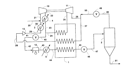
liquefaction of nitrogen. Referring now to Figure 1,
refrigerant gas 28, at a pressure generally within the
range of from 15 to 23 pounds per square inch absolute
15 (psia), is passed to recycle compressor 13 wherein it
is compressed to a first pressure within the range of
from 75 to 120 psia. The first pressure is roughly 5
to 6 times the inlet gas pressure. The ratio will
depend upon the cooling water temperature and the
20 desired capacity. Turndown corresponds to the lower
pressures. Resulting compressed refrigerant gas 24 is
cooled of heat of compression by passage through cooler
3 to give cooled compressed refrigerant gas 30.
Feed gas 20, i.e. low boiling point gas which in
25 this embodiment is nitrogen, is added to the compressed
refrigerant gas to produce working gas mixture 21. The
feed gas will generally have about the same composition
CA 02236360 1998-04-29
.
D-20373
as the refrigerant gas. Working gas mixture 21 is then
passed into booster compressor 10.
In addition, to, or alternatively to, the
arrangement illustrated in Figure 1, the feed gas may
5 be added to the refrigerant gas upstream of recycle
compressor 13. Such an alternative arrangement is
illustrated in Figure 2. Referring now to Figure 2,
feed gas 100 is added to refrigerant gas 28 to produce
working gas mixture 101. Mixture 101 is compressed by
10 passage through recycle compressor 13 to produce
compressed working gas mixture 102 at a first pressure
within the range of from 75 to 120 psia. Mixture 102
is cooled of heat of compression by passage through
cooler 3 and resulting cooled working gas mixture 103
15 is passed into booster compressor 10.
From this point in the cycle the two embodiments
illustrated in Figures 1 and 2 are similar and the
invention will be described with reference to both
Figures 1 and 2.
Within booster compressor 10 the working gas
mixture is compressed to a second pressure which
exceeds the first pressure and which is within the
range of from 115 to 180 psia. This second pressure is
generally about 1.5 to 1.6 times the recycle compressor
25 discharge pressure. Preferably the second pressure is
less than the supercritical pressure of the working
gas. Resulting elevated pressure working gas mixture
22 is cooled of heat of compression by passage through
cooler 4 and resulting cooled, elevated pressure
CA 02236360 1998-04-29
D-20373
working gas mixture 23 is divided into first portion 24
and second portion 40.
First portion 24 comprises from 60 to 90 percent,
preferably from 78 to 85 percent, of the elevated
5 pressure working gas mixture. First portion 24 is
cooled by partial traverse of heat exchanger 1 and
resulting cooled first portion 25 is passed from heat
exchanger 1 to turboexpander 11 wherein it is
turboexpanded to a pressure within the range of from 17
10 to 26 psia to produce cold refrigerant gas 26. As
illustrated in the Figures, it is preferred that the
turboexpander 11 be directly coupled with booster
compressor 10 so that the expansion within
turboexpander 11 serves to directly drive booster
15 compressor 10. It is an important aspect of this
invention that the working gas mixture is turboexpanded
through a single turboexpander, i.e. only one
turboexpander, to generate the refrigeration for the
subsequent liquefaction.
The cold refrigerant gas is passed to heat
exchanger 1. The embodiments illustrated in the
Figures are preferred embodiments wherein recycle vapor
50, as will be described in greater detail below, is
combined with stream 26 to form cold refrigerant gas
25 stream 27 which is passed to heat exchanger 1.
Second portion 40 comprises from 10 to 40 percent,
preferably from 15 to 22 percent, of the elevated
pressure working as mixture. Second portion 40 is
passed through valve 41 and passed as stream 42 to
CA 02236360 1998-04-29
D-20373
-- 10 -
positive displacement compressor 12 which is generally
a reciprocating compressor but may be a screw
compressor. Within positive displacement compressor
12, the second portion of the elevated pressure working
5 gas mixture is compressed to a supercritical pressure
to produce supercritical fluid 43. The supercritical
pressure will vary depending on the composition of the
fluid supplied to the positive displacement compressor.
For example, the supercritical pressure for nitrogen is
10 a pressure which exceeds 493 psia; the supercritical
pressure for oxygen is a pressure which exceeds 737
psia; the supercritical pressure for argon is a
pressure which exceeds 710 psia. When nitrogen is the
intended product, the supercritical pressure in the
15 practice of this invention will preferably be less than
1000 psia.
Supercritical fluid 43 is cooled by passage
through aftercooler 5 and resulting supercritical fluid
44 is passed into and through heat exchanger 1 wherein
20 it is cooled by indirect heat exchange with cold
refrigerant gas. Preferably, as illustrated in the
Figures, the flow of cold refrigerant gas through heat
exchanger 1 is countercurrent to the flow of
supercritical fluid through heat exchanger 1. After
25 passage through heat exchanger 1, the resulting
refrigerant gas 28 is passed to recycle compressor 13
as was previously described.
The supercritical fluid is recovered as product
cryogenic liquid. The Figures illustrate a preferred
CA 02236360 1998-04-29
D-20373
embodiment of the product recovery arrangement wherein
supercritical fluid 45, which has been cooled to a
temperature at which it would be a liquid if the fluid
were below the critical point, is throttled through
5 valve 46 to a pressure low enough to produce cryogenic
liquid. Resulting fluid 47, which comprises cryogenic
liquid, is passed into phase separator 2.
Alternatively, fluid 45 may be passed through a dense
phase expander in place of valve 46 to lower the
10 pressure of the fluid and produce cryogenic liquid.
Cryogenic liquid is withdrawn from phase separator 2 in
stream 51 and passed to a use point or to storage.
Typically, the flowrate of stream 51 will be less than
200 TPD of cryogenic liquid and generally will be
15 within the range of from 30 to 150 TPD of cryogenic
liquid. Vapor from phase separator 2 is withdrawn as
stream 48 passed through valve 49 and, as
aforedescribed stream 50, combined with stream 26 to
form cold refrigerant gas stream 27.
Table 1 records the results of a computer
simulation of one example of the invention carried out
in accord with the embodiment illustrated in Figure 1
and for the liquefaction of nitrogen. This example is
presented for illustrative purposes and is not intended
25 to be limiting. The stream numbers recited in Table 1
correspond to those of Figure 1.
CA 02236360 l998-04-29
D-20373
TABLE 1
Stream 20 21 24 25 26
Temperature, K 280.4 289.4 291.5172.6 101.8
Pressure, psia 120 110.9 117.8174.8 21.5
Flow, CFH (70~F, 141,500 984,400 774,600 774,600 772,700
14.7 psia)
Stream27 28 44 45 48 51
Temperature, K 101.0 290.5 291.5 102.5 82.5 83
Pressure, psia 21.5 18.7 496 496 21.5 27.2
Flow, CFH (70~F, 811,000 811,000 171,000 171,000 38,000 133,000
14.7 psia)
Although the invention has been described in
detail with reference to certain preferred embodiments,
those skilled in the art will recognize that there are
5 other embodiments of the invention within the spirit
and scope of the claims. For example, feed gas may be
added to the refrigerant gas between the stages of the
recycle compressor. High pressure feed gas may be
added downstream of the booster compressor and upstream
10 of the positive displacement compressor. Low
temperature feed gas may be added at various points in
the cycle. The invention may be practiced with other
equipment than that specifically recited in the
description of the preferred embodiments. Moreover,
15 the specific pressures and pressure ranges discussed
are for the liquefaction of nitrogen; when other gases
are to be liquefied the preferred pressures will differ
from those recited for the liquefaction of nitrogen.