Note: Descriptions are shown in the official language in which they were submitted.
CA 02236497 1998-OS-O1
- 1 -
EGRESS WINDOW LOCK
FIELD OF THE INVENTION
This invention relates to window locks and more particularly to
locks for sashes which are both slideable and swingable or tiltable as found,
for example, in single hung windows.
BACKGROUND OF THE INVENTION
At present, for locking sashes which are both slideable and tiltable
or swingable as, for example, the vertically sliding and tilting lower sashes
of
single hung window units the locks are mounted on tap of the lower sash
header to engage cooperating locking members or keepers mounted on the sill
of the upper sash. Two additional pieces of hardware are provided one at
each side of the lower sash to retain it against tilting. These latter locking
members normally incorporate spring actuated metal plungers which engage
in trackways provided in the window frame jambs to prevent unwanted sash
tilting. On retraction of the plungers, the lower sash can be tilted about its
bottom pivotal connections with its retaining shoes which in turn slide within
trackways in the window frame jambs.
2 5 Such present hardware is expensive and the presence of a lock on
top of the lower sash header limits the upward movement of the lower sash in
the window frame. Similarly, if the sash is slideably horizontally, the lock
on
one end of the sash limits its horizontal opening movement.
3 0 By so limiting the movement the sash, the size of the opening, that is
the egress opening, available when the sash is fully open is restricted. Thus,
for a given size of egress opening as required by many jurisdictions in which
the window is installed, the size of the window frame must be such that it
allows for the sliding movement of the sash to provide the required egress
CA 02236497 1998-OS-O1
- 2 -
opening plus an additional size to accommodate the lock mounted on the top
or end of the sash.
This requirement to accommodate the sash lock to achieve a
requisite egress opening for safety adds significantly both to the window
frame size and the sash area required to close the window frame adding
significantly to the cost of the window installation.
It is the object of the present invention to provide a novel and
extremely reliable low cost lock which will eliminate the present sash lock
thereby increasing the egress opening, will provide a very positive locking of
the sash in the closed position or at various open positions and will also
allow
for the tilting or swinging of the sash for cleaning or reglazing the window.
It is a further object of the invention to provide a lock as aforesaid
which incorporates a safety mechanism which will prevent accidental
unwanted tilting or swinging of the sash.
It is a further object of the invention to provide such a lock which
can be produced by injection molding.
SUMMARY OF THE INVENTION
The invention resides in providing a lock for a slideable and tiltable
or swingable window sash of a window unit, the lock comprising a housing
for mounting on the window unit to present a slideway extending
transversely of the sliding movement of the sash and a locking member having
3 0 a bolt end slideable in the housing slideway to move the bolt end between
an
intermediate projecting position for riding in a trackway to retain and guide
the window sash for sliding movement, a fully projecting position to engage in
a slot in the bottom of the trackway to lock the sash, and a fully retracted
position clear of the trackway to allow tilting or swinging of the sash, the
CA 02236497 1998-OS-O1
- 3 -
housing and locking member having cooperating means to releasably retain
the locking member when moved to the correct sash locking, sliding, and
tilting positions.
A further aspect of the invention resides in forming the housing and
locking member to provide a spring releasable positive stop preventing
accidental movement of the bolt from the sash sliding to the sash tilting or
swinging position.
In another aspect, the invention involves a lock incorporating the
aforesaid features in which both the housing and the locking member can be
formed by injection molding.
BRIEF DESCRIPTION OF THE DRAWINGS
Figure 1 is a perspective view showing the lock of the present
invention applied to a single hung window having a vertically slideable and
tiltable or swingable lower sash and showing the sash in a partially raised
2 0 position.
Figure 2 is a perspective view of the window of Figure 1 showing
the lower sash in a tilted position.
2 5 Figure 3 is an elevational view of the window of Figure 1 showing
the lower sash in the fully raised position.
Figure 4 is an elevational view of the window frame shown in
Figure 1, 2 and 3 but showing the lower sash with the prior art top lock in
the
3 0 fully raised position.
Figure 5 is an exploded fragmentary perspective view illustrating
one of the lower sash jambs to a which a lock of the present invention has
CA 02236497 1998-OS-O1
- 4 -
been attached and a window frame jamb on which the lower sash jamb is
adapted to slide.
Figure 6 is a plan view of the lower sash jamb and door frame jamb
illustrated in Figure 5 and showing the lock in its sash locking position.
Figure 7 is a view similar to Figure 6 but showing the lock in its sash
sliding position.
Figure 8 is a view similar to Figures 6 and 7 but showing the lock in
the sash tilting position.
Figure 9 is a perspective view of the lock with its bolt extended to
the locking position corresponding to Figure 6.
Figure 10 is a perspective view of the lock showing the bolt
partially retracted to the window sliding position corresponding to Figure 7.
Figure 11 is a perspective view of the lock showing the bolt fully
2 0 retracted corresponding to the sash tilting position of Figure 8.
Figure 12 is an exploded perspective view looking from the inner
side of the casing and the bolt carrying locking member.
2 5 Figure 13 is a perspective. view showing the locking member
assembled with the housing with the bolt in the sash sliding position.
Figure 14 is an exploded perspective view of the housing and
locking member looking from the outside of the housing.
Figure 15 is a perspective view of the housing and locking member
shown in Figure 14 assembled with the bolt in the sash sliding position.
CA 02236497 1998-OS-O1
- 5 -
Figure 16 is an elevational view looking at the inner side of the lock
and showing the locking member in the fully extended bolt position for
locking the lower sash.
Figure 17 is an enlarged view similar to Figure 16 but showing the
locking member moved to a position in which the bolt is partially retracted
between the sash locking and sash sliding positions.
Figure 18 is a horizontal section through the lock showing the bolt
in the sash locking position showing the button carried by the locking
member cantilever spring projecting through the housing slot.
Figure 19 is a view similar to Figure 18 but showing the locking
member moved to retract the bolt with the shoulder of the button carried by
the locking member spring cantilever riding on the inner surface of the
housing slot towards a stop shoulder provided towards the outer end of the
housing slot.
Figure 20 is a view similar to Figure 19 but showing the locking
2 0 member further retracted to further retract the bolt end with the button
depressed to clear its shoulder inwardly of the housing stop shoulder to allow
for total retraction of the bolt to the sash tilting position.
2 5 DETAILED DESCRIPTION ACCORDING TO THE PREFERRED
EMBODIMENTS OF THE PRESENT INVENTION
By way of illustration, the lock of the present invention will be
described as applied to a vertically slideable and tiltable sash but it will
be
3 0 understood that it can equally be applied to a horizontal slideable sash
which
can be swung out or "tilted" for cleaning and glazing.
With reference to the Figures, Figure 1 shows a window unit
comprising a window frame generally designated at 1 incorporating a fixed
CA 02236497 1998-OS-O1
- 6 -
upper sash 2 and a slideable and tiltable lower sash 3 to which the locks of
the
present invention generally designated at 4 have been applied.
Figure 1 shows the lower sash 3 slid vertically upwardly to a
partially open position while Figure 2 shows the lower sash 3 in a tilted
position.
Figure 3 is a front elevational view of the window unit of Figure 1
but showing the lower sash raised to its fullest extent with its header 5
abutting the header 6 of the window frame leaving an egress or escape
opening 7.
Figure 4 shows a lower sash 3' corresponding to the sash 3 but
provided with the conventional top lock 8. The presence of this top lock
limits upward sash movement preventing the header of the sash 3' reaching
the header of the window frame 1. As a result, the egress or escape opening 9
provided with the sash 3' fully raised is significantly less than the egress
opening 7 achieved with the use of the locks 4 of the present invention.
2 0 In many jurisdictions there is a minimum area of egress opening
required to enable escape through the window. If the egress opening 7 meets
the minimum standards required, the egress opening 8 would be unacceptable.
To increase the egress opening 8 would then involve increasing the size of the
window frame and as well the sizes of the sashes to fill the frame greatly
2 5 increasing the cost of the window unit.
Figure 5 is an illustration of an application of the use of the locks of
the present invention where the lock 4 has been secured to the sash jamb 10
adapted for sliding on the frame jamb 11.
The jambs 10 and 11 are generally typical extrusions with the sash
jamb 10 having a face 12 to which the lock 4 is shown mounted and with the
frame jamb 11 having a trackway 13 to slideably receive the conventional
shoe (not shown) to which the bottom of the sash 3 is pivoted for the tilting
CA 02236497 1998-OS-O1
action. The frame jamb 11 is also provided with a flange 14 to prevent
outward sash movement and a bolt receiving track 15 having one or more
openings or notches 16 in the bottom wall 17 thereof for a purpose as will
hereinafter appear.
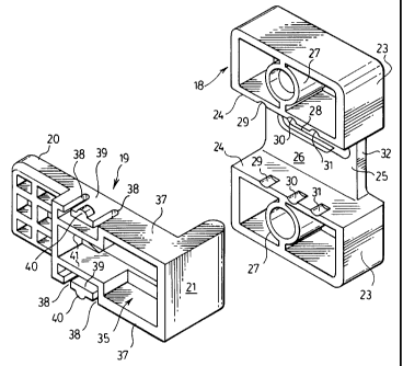
The lock 4 comprises two parts, a housing 18 for mounting the lock
on the sash jamb 10 and a locking member 19 slideable in the housing and
having an end in the form of a bolt 20 and a finger grip 21.
l0 The locking member 19 has three operating positions illustrated in
Figures 6, 7 and 8. Figure 6 shows the position in which the bolt 20 is fully
extended projecting into the trackway 15 and through the notch 16 to lock
the sash from sliding movement in the window frame. It will be understood
that the location of the trackway opening or notch 16 will register with the
bolt 20 with the lower sash fully closed to lock the sash in the closed
position.
Other notches may be provided in the trackway 15 to enable the window to
be locked against sliding movement in various raised positions as desired.
Figure 7 shows the bolt 20 retracted from the opening 16 in the
2 0 track bottom wall 17 but contained within the trackway enabling the sash
to
be slid vertically with the bolt riding in the trackway but preventing inward
tilting or falling of the sash.
Figure 8 shows the bolt 20 fully retracted from the trackway 15 to
2 5 allow tilting of the sash about its pivotal connection with the bottom
shoes as
will be understood.
Figures 9, 10 and 11 show the three positions of the locking member
corresponding to Figures 6, 7 and 8, that is, with the bolt fully extended to
the
3 o sash locking position in Figure 9, the bolt partially retracted to the
sash sliding
position in Figure 10 and the bolt fully retracted to the sash tilting
position in
Figure 11.
CA 02236497 1998-OS-O1
_ g _
Figures 12 to 20 show the details of the lock housing 18 and
slideable locking member 19 which are formed as injection molded parts of
nylon or nylon reinforced with glass or other suitable material which will
give
equivalent strength and durability it being understood that such parts can be
produced in large volume at relatively low cost.
The housing 18 which is of channel shape comprises a face plate 22
carrying two spaced generally rectangular box sections 23 projecting laterally
therefrom with the opposing walls 24 of the sections 23 being parallel and
to defining with the portion 25 of the face plate 8 spanning therebetween a
slideway 26 to slideably receive the locking member 19. It will be understood
that with the channel shaped housing mounted on the sash jamb as illustrated
the jamb will close the open side of the housing providing a closed slideway
for containing the locking member 19.
The box sections 23 of the housing have centrally thereof a hollow
fastener receiving column 27 opening at 27a through the face plate 22.
Suitable fasteners 28b projected through the openings 27a and columns 27
enable the housing 18 to be easily and quickly fastened at an appropriate
2 0 position on the sash with the slideway extending perpendicular to the sash
jamb.
As shown, eg. in Figures 14 and 15, the portion 25 of the face plate
22 between the box sections 23 has an longitudinal slot 28 therein extending
2 5 longitudinally of the slideway 26 and exposed centrally thereof.
As shown particularly in Figure 12, the opposing walls 24 of the
box sections 23 are provided with registering locating notches 29, 30 and 31
corresponding to the sash locking, sash sliding and sash tilting positions of
the
3 0 locking member respectively.
One side the face plate portion 25 is notched as at 32 to enable the
end of the locking member 19 provided with the finger grip 21 to lie flush
with
CA 02236497 1998-OS-O1
g _
the respective sides of the box sections 23 with the locking member moved to
sash locking position.
As shown in Figure 14 and more particularly in Figures 18 to 20, the
wall of the slot 28 is reduced in thickness over a length indicated at 33
corresponding to the distance of the movement of the locking bolt from the
sash locking to the sash sliding position and forms a stop shoulder 34
rearwardly of the bolt sash sliding position, that is, between the sash
sliding
position and the sash tilting position. This stop shoulder 34 is provided to
prevent accidental movement of the locking member to the sash tilting
position thus providing an important safety feature as hereinafter more fully
explained.
With reference to Figures 12 and 14 in particular, the locking
member 19 has a box section 35 adapted to snugly slide in the housing
slideway 26 as shown in Figure 13.
The side of the box section 35 facing the housing section 25 is
closed by a planar slide portion or plate 36 which extends outwardly to form
2 0 part of the thickened generally planar bolt end 20 as shown in Figure 14.
The opposing walls 37 of the box section 35 of the locking member
which slide along the opposing walls 24 of the slideway 26 are slotted as at
38 to provide short cantilever sections 39 which have a measure of resiliency.
These cantilever sections 39 carry outwardly projecting rounded detentes 40
at their free ends for engagement in the respective notches or grooves 29, 30
and 31 in the slideway walls 24 for accurately locating the locking member in
the fully extended sash locking bolt position, the partially retracted sash
sliding bolt position, and the fully retracted sash tilting bolt position.
For strengthening of the box section 35 of the locking member, the
cantilevers 39 are bridged by spaced walls 41 located interiorly of the box
section.
CA 02236497 1998-OS-O1
- 10 -
As illustrated particularly in Figure 14, the sliding or plate portion 36
closing one side of the box section 35 is provided with an elongated U-slot 42
defining an elongated cantilever arm 43 extending lengthwise of the locking
member and centrally thereof. A button 44 is mounted at the free end of the
cantilever 43 through a shoulder abutment 45.
With the locking member assembled with the housing as shown, for
instance, in Figure 15, the button 44 is projected through the housing slot 28
with the shoulder abutment 45 contacting the surface of the housing face
portion 25 along the thinned portion 33 of the slot 28.
Figure 16 shows the locking member 19 in the sash locking position
with the bolt end 20 fully extended and with the detentes 40 carried on the
short cantilevers 39 of the locking member seated in the grooves or notches
29 of the housing slideway walls 24 to provide an overcomable resistance to
the retraction of the locking member from the sash locking position.
Figure 17 shows the commencement of the retraction of the locking
member towards the sash sliding position which will be obtained when the
detentes 40 register with the grooves 30.
During this retraction movement of the locking member, the button
44 will remain exposed and move in the housing slot 28 with the abutment
shoulder 45 moving freely in the section 33 of the slot having a reduced
2 5 thickness until the bolt is retracted to the sash sliding position.
Thereafter
interference between the abutment shoulder 45 and the stop shoulder 34 will
prevent any further retraction of the. locking member so that accidental
movement of the bolt from a partially retracted sash sliding position to the
sash tilting position is precluded. This arrangement prevents any unwanted
3 0 inward tilting of the sash that might cause injury or breakage of the
glass.
When however it is desired to fully retract the bolt to the sash tilting
position, the elongated cantilever 43 provides sufficient resilience that by
depressing the button 44 as shown in Figure 20 the abutment shoulder 45 can
CA 02236497 1998-OS-O1
- 11 -
be moved clear of the stop shoulder 34 allowing the complete retraction of the
bolt 20 for the sash tilting operation.
In the illustrations the locks 4 are shown mounted on the sash jambs
10 adjoining the tops thereof. It will be appreciated that they may also be
mounted on the ends of the sash header 5 or any position relative to the sash
3 and window frame 1 such that the bolt 20 engages in a guiding and
retaining slot in the intermediate sash sliding position, enters a notch in
the
bottom of the slot in the sash locking position and is retracted clear of the
slot
in the sash tilting position.
While the operation of the lock has been described in connection
with a vertically slideable and tiltable sash, it can equally as well be used
on
horizontally slideable sashes which can be swung out (usually referred to as
tiltable) for cleaning and glazing.
It will be understood that the use of the lock of the present
invention whether on a vertically slideable or a horizontally slideable
"tiltable"
sash, will provide for maximum area of egress opening with minimum sash area
2 o for a given window frame area.
It will also be understood that with the lock of the present
invention a simple lock mounted at each side of the sash performs all of the
window functions required eliminating the need for the relatively expensive
and additional hardware presently required to achieve these functions.
Further, the lock of the present invention provides an important
safety feature avoiding accidental or unwanted sash tilting or swinging which
can occur with conventional lock arrangements.
It will also be understood that variations in details of the lock
components may be made without departing from the scope of the appended
claims.