Note: Descriptions are shown in the official language in which they were submitted.
CA 02236731 2001-O1-10
HAND OPERATED CHAIN BLOCK
The present invention relates to a hand operated chain block and,
more particularly, to a hand operated chain block wherein a load sheave
is rotationally driven by pulling a hand chain passing over a hand wheel,
so as to wind up and down a load chain passing over the load sheave.
In general, a hand operated chain block of this type includes a
load sheave supported between a pair of side plates via bearings, and a
hand wheel for driving the load sheave through a drive shaft. The hand
wheel is rotationally driven by pulling a hand chain passing over the
hand wheel, to cause the load sheave to be rotationally driven, so as to
wind up and down the load chain wound over the load sheave.
The load chain of an unloading side, opposite to the loading side of
the load chain suspending a load, is fixed at the end by a fixing pin
between the pair of side plates. Further, in order to allow the load
chain to smoothly pass over the load sheave to ensure smooth winding
up and down operation, a generally semi-circular chain guide for guiding
the load chain to be wound over the load sheave is provided around the
load sheave between the pair of side plates, so as to lay over the load
sheave. A chain split for guiding the load chain to be moved to and
from the load sheave is provided under the load sheave.
For enabling the fixing pin for fixing the end of the load chain of
1
CA 02236731 2001-O1-10
an unloading side to be easily assembled in between the pair of side plates,
the fixing pin should be preferably inserted from the outside of any one
of the two side plates at the last stage of assembly. On the other hand,
at the last stage of assembly, the hand wheel, the gear cover and other
components are already assembled in the chain block body, so the
position for the fixing pin to be assembled is limited to a marginal portion
around the each side plate.
If the fixing pin is located at an excessively inner position in the
marginal portion around the each side plate, there is a fear that when
the load chain of a loading side is wound up, a chain link of the load chain
of
an unloading side fixed to the fixing pin and a chain link of the load chain
moving to the unloading side may contact with each other and become
tangled, to hinder smooth winding operation.
On the other hand, if the fixing pin is located at an excessively
outer position, then the side plates must be increased in width, and
accordingly the chain block cannot be reduced in size. In addition to
this, when a full length of the load chain of loading side is wound down,
the load chain of an unloading side is tensed between the fixing pin and the
load
sheave, to cause a problem that the load chain of an unloading side tensed
pushes up the chain guide to cause deformation of the chain guide.
It is the object of the invention to provide a hand operated chain block
capable of fixing an end of the load chain of an unloading side and also
ensuring
smooth wind up and down operation of the load chain, while reducing the size
of chain block.
2
CA 02236731 2001-O1-10
According to one aspect of the present invention, there is provided a
novel hand operated chain block comprising: a load sheave which is supported
between a pair of side plates via bearing means and over which a load chain is
wound; a fixing means, provided between the pair of side plates, for rotatably
supporting an end of the load chain of an unloading side opposite to the
load chain of a loading side; a chain guide, provided over and extending
along the load sheave, for guiding the load chain to be wound over the
load sheaves and a chain split, provided under the load sheave, for
guiding the load chain to run into and from the load sheave, wherein the
fixing means is located at a position in a marginal portion around each
side plate such that a space between the chain split and a rotation
trail of a tip of an end portion on the loading side of a first link of the
load
chain rotatably supported by the fixing means can be made larger than a
width of a link of the load chain, and also that when a full length of the
load chain of a loading side is wound down, an end portion on the loading
side of a second link next to the first link can abut with the end portion
on the unloading side of the chain guide.
With this arrangement, the fixing means for rotatably supporting
the load chain of an unloading side is located at a position in a marginal
portion around each side plate, so that the fixing means is easily
assembled at the last stage of assembly of the chain block. Also, a
space between the chain split and a rotation trail of the tip of the end
portion on the loading side of the first link of the load chain rotatably
3
CA 02236731 2001-O1-10
supported by the fixing means is set to be larger than a width of a link of
the load chain, so that when the load chain of a loading side is wound up,
the first link and a link of the load chain wound down to the unloading
side are prevented from being brought into contact and tangle with each
other to ensure a smooth winding up operation. In addition, when the
full length of the load chain of a loading side is wound down, an end
portion on the loading side of the second link next to the first link is
brought into abutment with the end portion on the unloading side of the
chain guide, to allow the third link next to the second link to run into
between the load sheave and the chain guide at an angle at which the
load chain extends along the chain guide. This enables the load chain
to be avoided pushing up the chain guide to prevent deformation of the
chain guide. Besides, the high rigidity end of the second link is brought
into contact with an end portion of an unloading side of the chain guide, so
that fatigue failure of the second link can be minimized to enhance
durability of the load chain. Consequently, a smooth wind up and down
operation of the load chain can be ensured, while reducing the size of
chain block.
According to the present invention, it is preferable that the fixing
means includes a supporting shaft for supporting thereon the first link,
and the supporting shaft is provided with a stepped portion for restricting
an axial movement of the'first link. The stepped portion of the
supporting shaft, by which the axial movement of the first link is
restricted, enables the transverse movement of the load chain between
the pair of side plates to be restricted, so as to smoothly guide the load
4
CA 02236731 2001-O1-10
chain into between the load sheave and the chain guide. Hence, the
load chain can be smoothly wound up and down.
According to the present invention, it is preferable that the
supporting shaft has a shaft supporting portion for supporting thereon
the first link, and the shaft supporting portion is formed into an
elliptical shaped section. Forming the shaft supporting portion directly
supporting thereon the first link with an elliptical shaped section enables
strength of the supporting shaft to be improved. Consequently,
strength of the fixing means can be enhanced to contribute to
improvement in durability of the chain block.
BRIEF DESCRIPTION OF THE DRAWINGS
The present invention will now be described with reference to the
accompanying drawings wherein:
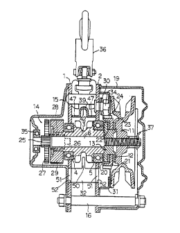
Fig. 1 is a vertical section of the hand operated chain block of an
embodied form of the present invention;
FIG. 2 is a sectional view, sectioned vertically along a center
between a pair of side plates, showing the state of the load chain 9
being wound over the load sheave 3;
FIG. 3 is a sectional view, corresponding to FIG. 2, showing the
state of a full length of the load chain 9 of loading side being wound
down;
FIG. 4 is an illustration showing the state of the chain guide 39
being fitted to the left side plate 1;
FIG. 5 is a sectional view taken along line A-A of FIG. 3;
FIG. 6 is a showing of the main part of the outer wall of the right
5
CA 02236731 1998-OS-OS
side plai:e 2, illustrating the fitting of the fixing pin 40;
FIG. 7 is a front view of the fixing pin 40; and
FIG. 8 is a side elevation view of the fixing pin 40.
DET~41LED DESCRIPTION OF THE PREFERRED EMBODIMENT
Referring now to the accompanying drawing figures, an example
of the preferred embodiment of the invention is described below. It is
to be understood, however, that the scope of the invention is by no
means limited to the illustrated embodiments.
FIG. 1 is a vertical section of the hand operated chain block of an
embodif:d form of the present invention. In this hand operated chain
block, a load sheave 3, over which a load chain 9 (shown in FIGS. 2, 3
and 5 only) passes, is rotatably supported between a pair of spaced
apart, opposing, right and left side plates 1, 2 via a pair of bearings 4, 5,
and a derive shaft 6 is supported with inserted in a shaft bore of the load
sheave 3 so as to be rotatable relative to the load sheave. A hand
wheel 11 over which a hand chain (not shown) is wound is threadedly
engaged with the drive shaft 6 at one axial end thereof at the outer side
of the right side plate 2. A set pin 37 is inserted in the axial end portion
of the drive shaft 6. A transmission mechanism 13 including a
mechanical brake 12 is provided between the hand wheel 11 and the
load sheave 3.
The transmission mechanism 13 comprises: a driven hub 20 which
is so connected to the drive shaft 6 as to be non-rotatable relative
thereto (connected in a threasded relation thereto in FIG. 1 ); a reverse
rotation stop gear 21 interposed between a flange portion of the driven
6
CA 02236731 1998-OS-OS
hub 20 and the hand wheel 11 and rotatably supported by the driven hub
20; and lining plates 22, 23 interposed between the driven hub 20 and
the reverse rotation stop gear 21 and between the reverse rotation stop
gear 21 and the hand wheel 11, respectively. The right side plate 2 is
provided with a pawl shaft 34, to which a reverse rotation stop pawl 24
engageable with the reverse rotation stop gear 21 is swingably attached.
Between the reverse rotation stop gear 24 and the right side plate 2 is
interposed a pawl spring 30 biasing the reverse rotation stop pawl 24
toward t:he reverse rotation stop gear 21. The mechanical brake 12 is
composed of the reverse rotation stop pawl 24, the reverse rotation stop
gear 21, the driven hub 20, and the lining plates 22, 23.
On the other hand, the drive shaft 6 is supported by a bearing 35
at the other axial end, and a geared reduction mechanism 14 including a
plurality of reduction gears is provided between the bearing 35 and load
sheave 3 at the outer side of the left side plate 1. The geared
reduction mechanism 14 comprises: a first gear 25 formed integrally
with an axial end portion of the drive shaft 6; a pair of second gears 27
engaged with the first gear 25 and supported by a pair of intermediate
shafts c'6; a pair of third gears 28 engaged with the second gears 27 and
supported by the pair of intermediate shafts 26 (only each one of the
pairs of intermediate shafts 26, second gears 27 and third gears 28 is
represented in FIG. 1 ); and a fourth gear 29 connected to an extension
of the load sheave 3 and engaged with the third gears 28.
A. gear cover 15 for covering the geared reduction mechanism 14
and a v~rheel cover 19, opening at one side thereof, for covering the hand
7
CA 02236731 1998-OS-OS
wheel 11 are detachably mounted on the outer sides of the pair of left
and right side plates 1, 2, respectively, by three stay bolts 16, 17 and 18
connecting the pair of side plates 1, 2 (only one stay bolt 16 is
represented in FIG. 1 ). Interposed between the right side plate 2 and
the hand wheel 11 is a brake cover 31 for covering the periphery of the
reverse rotation stop gear 21. 36 denotes a hanging hook for hanging
a chain block.
When the hand wheel 11 is driven in the normal rotation direction
by pulling the hand chain 9, the drive shaft 6 is driven through the
transmission mechanism 13. The drive of the drive shaft is transmitted
to the load sheave 3 through the geared reduction mechanism 14, to
rotationally drive the load sheave 3, so that the load chain 9, passing
over thE~ load sheave 3, of loading side, in other words, the side of load
chain having at the foremost end thereof a hook and suspending a load,
is wound up to hoist up the load. The hoisted load is maintained in
suspension through the action of the mechanical brake 12.
Vl~~hen the hoisted load is lowered, the hand wheel 11 is driven in
reverse by pulling the hand chain. The hand wheel 11 driven in reverse
is screwed backwards along the drive shaft, to drive the load sheave 3 in
reverse, while the mechanical brake 12 is alternately actuated and
deactuated, so as to lower the load gradually.
FIG. 2 is a sectional view, sectioned vertically along a center
between a pair of side plates, showing the state of the load chain 9
being wound over the load sheave 3; FIG. 3 is a sectional view,
corresF~onding to F1G. 2, showing the state of a full length of the load
8
CA 02236731 1998-OS-OS
chain 9 of loading side being wound down; FIG. 4 is an illustration
showing the state of the chain guide 39 being fitted to the left side plate
1; FIG. 5 is a sectional view taken along line A-A of FIG. 3; FIG. 6 is a
showing, of the main part of the outer wall of the right side plate 2,
illustrating the fitting of the fixing pin 40; FIG. 7 is a front view of the
fixing pin 40; and FIG. 8 is a side elevation view of the fixing pin 40.
The fixing means for supporting the load chain 9 of unloading side
through it will be described with reference to FIGS. 1 to 8.
In FIG. 2, the load chain 9 is wound over the load sheave 3, and
an end portion of the load chain 9 of unloading side which is opposite to
the loading side of the load chain 9 across the load sheave 3, i.e., the
first IinN; 41 at the foremost end of the load chain of unloading side, is
supported by a fixing pin 40 forming the fixing means.
A generally semi-circular chain guide 39 for guiding the load chain
9 to be wound over the load sheave 3 is arranged over and extends
along the load sheave 3 with spaced apart therefrom at a given interval,
so as t~o lay over the load sheave 3. The chain guide 39 has a thin-
plate fc>rm in section having a width substantially equal to the interval
between the pair of side plates 1 and 2, as shown in FIG. 1. The chain
guide 39 has a convexed groove 42, of generally semi-circular in section,
for accommodating an upper portion of each vertical link 45 of the load
chain 9 to guide the vertical links 45; and a flat portion 47, formed flat at
both sides of the convexed groove to extend continuously therefrom in
the longitudinal direction, for guiding each horizontal link 46 of the load
chain 9. As shown in F1G. 2, the chain guide 39 is provided, at an end
9
CA 02236731 1998-OS-OS
portion thereof on the loading side, with a loading-side guide portion 43,
having an end directing upward for guiding the load chain 9 to be
smoothly run into between the load sheave 3 and the chain guide 39.
Also, the chain guide 39 is provided, at an end portion thereof on the
unloading side, with a similar, unloading-side guide portion 44, having
an end directing upward for guiding the load chain 9 to be smoothly run
into between the load sheave 3 and the chain guide 39.
As. shown in FIG. 4, for example, the chain guide 39 is provided
with a plurality of projections 48 extending continuously outwardly from
the flat portion 47, while on the other hand, the each side plate 1, 2 (FIG.
4 illustrates the left side plate 1 only) is provided with a plurality of
fitting
holes 49 for fitting the projections 48 therein. After the projections 48
are fitted into the fitting holes 49, three stay bolts 16, 17, 18 are
tightened to hold the chain guide 39 in sandwich relation between the
both side plates 1, 2 to thereby support the chain guide 39
therebetween.
As shown in FIG. 2, a chain split 32 for guiding the load chain 9 to
be movE~d to and from the load sheave 3 is provided under or generally
right under the load sheave 3. As shown in FIG. 1, the chain split 32
has a generally rectangular plate-like form, and includes a plate-like
portion 'via which the chain links of the load chain 9 of loading side and
those of unloading side are guided to be smoothly moved to and from
the load sheave 3; and a convexed projection 50 extending continuously
to a generally top center part of the plate-like portion. The convexed
projection 50 acts to kick back the chain links of loading side and of
CA 02236731 1998-OS-OS
unloading side wound down from the load sheave 3, to smoothly
disengage the chain links from the load sheave 3, so as to prevent the
load chain 9 from being jammed into the load sheave 3. Also, as
shown in F1G. 1, the chain split 32 is provided, at each side thereof, with
an outward projection 51, while on the other hand, each of the side
plates 1, 2 is provided with a fitting hole 52 fittable with the projection
51.
After the projections 51 are fitted into the fitting holes 52, the three stay
bolts 16, 17, 18 are tightened to hold the chain split 32 in sandwich
relation between the both side plates 1, 2 to support the chain split 32
therebetween.
In this arrangement of the embodied form, the fixing pin 40 is
located at a position in a marginal portion around each side plate 1, 2
such that an interval 73 between the chain split 32 and a rotation trail 54
of the tip of an end portion 53 on the loading side of the first link 41 of
the
load chain 9 rotatably supported by the fixing pin 40 can be made larger
than a width of a link of the loading chain 9, as shown in FIG. 2, and also
that when the full length of the load chain 9 of loading side is wound
down, an end portion 56 of the second link 55 next to the first link 41 can
abut with the end portion on the unloading side of the chain guide 39, as
shown in FIG. 3.
A,s shown in FIGS. 2 and 3, the fixing pin 40 is provided between
the pair of the side plates 1, 2 at the marginal portion therearound. For
enabling the fixing pin 40 to be easily assembled in between the pair of
side plates 1 and 2, the fixing pin 40 should be preferably inserted from
the outside of any one of the two side plates 1, 2 at the last stage of
11
CA 02236731 1998-OS-OS
assembly of the chain block. This is because, since the hand wheel 11,
the gear cover 15 and others are already assembled in the chain block
at the last stage of assembly, the position for the fixing pin 40 to be
inserted without being hindered by the assembled components is limited
to a marginal portion around the each side plate 1, 2.
If the fixing pin 40 is located at an excessively inner position in the
marginal portion around the each side plate 1, 2, there is a fear that
when the load chain 9 of loading side is wound up, the first link 41
rotatably supported by the fixing pin 40 and chain links of the load chain
9 being wound down to the unloading side may contact with each other
and become tangled, so as to hinder smooth winding up operation. For
this reason, as shown in FIG. 2, the fixing pin 40 is placed at a position,
spaced positional relation with the chain split 32, such that an interval
(indicated by an arrow at 73) between a rotation trail 54 of the tip of the
end portion 53 on the unloading side of the first link 41 and a plate-like,
unloading-side, wall surface 57 of the chain split 32 can be made larger
than a width of a link (e.g. a link 58 indicated by a phantom line in FIG.
2) of the load chain 9. The fixing pin 40 located at this specific position
can produce the result that when the load chain 9 of loading side is
wound up, a link of the load chain 9 wound down to the unloading side
(the state of a third link 60 being wound down in the direction indicated
by an arrow 59 is illustrated by the link 58 depicted by a phantom line in
FIG. 2) and the first link 41 can be prevented from being brought into
contact and tangle with each other to ensure a smooth winding
operation.
12
CA 02236731 2001-O1-10
On the other hand, if the fixing pin 40 is located at an excessively
outer position in the marginal portion around each side plate 1, 2, then
the side plates 1, 2 must be increased in width, and accordingly the
chain block cannot be reduced in size. In addition to this, when a full
length of the load chain 9 of a loading side is wound down, the load chain
9 of an unloading side is tensed between the fixing pin 40 and the load
sheave 3, to cause a possible problem that the load chain 9 of an unloading
side tensed pushes up the chain guide 39 to cause deformation of the
chain guide 39. For this reason, as shown in FIGS. 3 and 5, the fixing
pin 40 is located at a position such that when the full length of the load
chain 9 of a loading side is wound down, an end portion 56 on the loading
side of the second link 55 next to the first link 41 can abut with the flat
portion 47 in the unloading-side guide portion 44 at the end on the
unloading side of the chain guide 39. The fixing pin 40 located at this
specific position brings the end 56 on the loading side of the second link
55 into contact with the flat portion 47 of the unloading-side guide
portion 44 when the full length of the load chain 9 of loading side is
wound down, and as such can allow the third link 60 next to the second
link 55 to run into between the load sheave 3 and the chain guide 39 at
an angle at which the load chain extends along the chain guide 39 via
the unloading-side guide portion 44. This enables the load chain 9 to
avoid pushing up the chain guide 39 to prevent deformation of the
chain guide 39. Besides, as shown in FIG. 5, the end 56 on the loading
side of the second link 55, which is a high rigidity part, is brought into
contact with each side of the flat portion 47 of the chain guide 39, so that
13
CA 02236731 2001-O1-10
fatigue failure of the second link 55 due to the contact is minimized to
enhance durability of the load chain 9. In addition, since the chain
guide 39 enables a force applied from the second link 55 to be
dispersed over the each side of the flat portion 47, the force exerted on
the chain guide from the contact can be reduced to enhance durability of
the chain guide 39.
Accordingly, the arrangement of the fixing pin 40 at this specific
position can produce the advantageous effects of facilitating the
assembly of the fixing pin at the last stage of assembly and also
ensuring smooth wind up and down operation of the load chain, while
reducing the size of chain block.
Next, the assembly of the fixing pin 40 in between the pair of side
plates 1 and 2 will be described. As shown in FIG. 5, insertion bores
61, 62, 63 for inserting the fixing pin 40 therein are respectively bored in
marginal portions around the gear cover 15 and two side plates 1 and 2
at the positions corresponding to the fixing fin 40 located at the position
described above. On the other hand, as shown in FIGS. 7 and 8, the
fixing pin 40 includes a supporting shaft 66 for supporting thereon the
first link 41; a head 67 having a larger diameter than the supporting
shaft 66 and formed into a circular shape at one end of the supporting
shaft 66; and a pin hole 64, formed at the other end, for inserting a set
pin 65 therethough. As shown in FIG. 5, the fixing pin 40 is inserted
into the insertion bores 61, 62 of the gear cover 15 and the left side
plate 1 from the outside of the gear cover 15, to allow the supporting
shaft 66 to pass through the first link 41 between the both side plates 1
14
CA 02236731 1998-OS-OS
and 2 and then inserted in the insertion bore 63 of the right side plate 2,
and thereafter, the set pin 65 is fitted into the pin hole 64, as shown in
FIG. 6. Thus, the fixing pin 40 is rotatably assembled between the both
side plates 1 and 2.
It is noted that the fixing pin 40 may be adapted to be inserted
from the outside of the right side plate 2 for the assembly, and a known
means, such as a snap ring, may be used for fixture, instead of the set
pin 65.
In addition, as shown in FIGS. 7 and 8, the supporting shaft 66 of
the fixing pin 40 is provided with a stepped portion 68 for restricting an
axial movement of the first link 41. The stepped portion 68, by which
the axial movement of the first link 41 is restricted, enables the
transverse movement (in the direction indicated by an arrow 69 in F1G.
5) of the load chain between the pair of side plates 1 and 2 to be
restricted, as shown in FIG. 5, so as to smoothly guide the load chain 9
into between the load sheave 3 and the chain guide 39. Hence, the
load chain 9 can be smoothly wound up and down. In addition to the
stepped portion 68 acting to restrict the transverse movement of the first
link 41 between the both side plates 1 and 2 from one lateral side only, a
cylindrical member 70 indicated by a phantom line in FIG. 5 may be
used in some cases. When the fixing pin 40 is assembled, the first link
41 is first fitted onto the supporting shaft 66 and then the cylindrical
member 70 is fitted onto the supporting shaft and secured thereto.
With this arrangement, the transverse movement of the first link 41
between the both side plates 1 and 2 can be restricted from both sides
CA 02236731 2001-O1-10
by the stepped portion 68 and the cylindrical member 70, to support the
first link at a more proper position.
As shown in FIGS. 7 and 8, the supporting shaft 66 of the fixing
pin 40 is composed of a shaft supporting portion 71 of an elliptical shaped
section on which the first link 41 is supported and a large diameter
portion 72 slightly larger than a major axis of the shaft supporting portion
71 of the elliptical shaped section. Forming the shaft supporting
portion 71 directly supporting thereon the first link 41 into ellipse-like
shape in section enables the strength of the supporting shaft 66 to be
improved without increasing the diameter of the supporting shaft 66, in
other words, within the range of the supporting shaft being insertable in
an aperture of a link of standardized size. Thus, the shaft supporting
portion 71 and the large diameter portion 72 having a larger diameter
enables the entire strength of the fixing pin 40 to be improved, to
contribute to improvement in durability of the chain block.
Also, the illustrated embodiment takes the arrangement in which the
hand wheel 11 is directly screwed with the drive shaft 6, but may take a
modified arrangement in which a hub is threadedly engaged with the
drive shaft 6; the hand wheel 11 is rotatably supported on the hub; and
an overload prevention mechanism for applying resistance to rotation of
the hand wheel 11 is provided between the hub and the hand wheel 11.
16