Note: Descriptions are shown in the official language in which they were submitted.
CA 02237010 l99X-0~-07
W O 97/17483 PCTrUS96/17867
Catalytic Structures and Method of Manufacture
R-~k~round of the Invention
The present invention relates to catalytic structures and their
method of manufacture particularly as a part of or in association with heat
5 exchangers, such as automotive radiators and air conditionin g condensers.
The catalytically active material may comprise the fins of the heat
exchanger or be incorporated into a separate catalytic structure.
A significant air pollution problem is created by motor vehicles from
the production and emission of substances such as carbon monoxide and
10 ozone. It has been proposed that motor vehicles be equipped with
catalytic reactors which would catalytically convert the pollutants contained
in the air through which the vehicles are traveling. Specifically, it has been
proposer~ that the heat exchange surface in a motor vehicle, such as the
radiator and air conditioning condenser, be coated with the catalytic
15 material which would then provide a large surface area of heated catalyst
material traveling along the roadways at the situs where large quantities
of these particular pollutants are produced.
The prior discloser~ processes for forming a catalyst coating on a
heat exchanger relate to the ~pplic~tion of the catalyst material to a
20 ,~rt:fGr")ed heat exchange structure by applying the catalyst material,
usually platinum, such as by a wash-coat that is sprayed or painted onto
the formed heat exchanger. Applying such coating into the already formed
small interstices of such a device presents a significant problem. Also, the
catalyst materials are usually applied as salts which then require the
25 additional step of calcining to covert the salts to the catalyst metal. On the
other hand, applying the catalyst coating to the components of a heat
exchanger, such as the stock material for the heat exchanger fins, prior to
fabrication presents its own problem since most such coatings cannot
withstand the fabrication processes such as cutting, bending, punching,
30 etc. They are inherently brittle and sp~ hle or they can delaminate.
_
,
CA 02237010 1998-0~-07
W O 97/17483 PCTnUS96/17867
Summary of the Invention
The present invention relates to catalytic structures and the method
of forming the same. In particular, the extended heat exchange surface
ffins) of a heat exchanger are constructed of a fin stock which has already
5 been prepared to include a firmly anchored catalyst material. Specifically,
one embodiment of the invention involves a heat exchanger and the
method of forming the heat exchanger wherein the stock material for the
fins comprises a substrate with a porous anodic oxide coating and metallic
nodules which include a catalytic metal anchored in the pores and
10 extending above the surface of the coating. The nodules may be formed
entirely of the catalyst metal or may initially be formed of a different, first
metal which is then coated with the catalyst metal. The nodules are
formed by electrodeposition of the metal. As an alternative, the deposit of
the catalyst metal on the nodules may be continued so that the catalyst
15 metal bridges over from one nodule to another to cover essentially the
entire surface. The stock material for the fins with the catalyst formed
thereon is then fabricated into heat exchanger fins and assembled with the
heat exchanger tubes to form the heat exchanger. In the alternative, the
catalytic stock material may be formed into a separate catalytic structure
20 mounted for the flow of air therethrough and preferably in air-flow
relationship to a heat exchanger.
Brief D_scri~tlon of the n,"~ I~.gs
Figure 1 is an enlarged cross-sectional view depicting a metal
nodule formed in a pore of an anodic oxide layer on a metal substrate and
25 extending above the surface thereof with a catalyst metal coating thereon;
Figure 2 is a diagrammatic representation of one possible process
for continuously anodizing an aluminum or other metal web and plating
metal nodules thereon according to the present invention;
Figures 3 and 4 are enlarged cross-sectional views depicting
30 variations in the ~leposition of the catalyst metal;
CA 02237010 1998-0~-07
W O 97/17483 PCTrUS96/17867
Figure 5 illustrates a heat exchanger formed with the catalyst-
containing fin stock of the present invention;
Figure 6 illustrates an alternate embodiment of the present invention
wherein the catalyst fin material is formed as a separate structure adjacent
, 5 to the heat exchanger.
Descrlption of the r~ef~r~ Embodiment
According to the first step of the present invention, a porous anodic
oxide coating is formed on the surface of a substrate metal plate or web
preferably made of aluminum. The substrate could also be other
anor~ hlQ metals such as titanium or aluminum bonded to another
material such as steel. The substrate metal may be generally smooth or
it may be roughened to form a grained or pitted surface. Conventional
graining techniques such as brush graining with an abrasive can be
employed or more severe roughening such as scratching, etching or roll
forming a uniform pattern can be used to obtain greater asperity. The
formation of porous anodic oxide coatings in the anodizing process is well
known in the art and is accomplished by using the known electrolytes
which result naturally in porosity such as sulfuric acid, phosphoric acid and
chromic acid to name a few. Nodules ranging in size from several microns
to sub-micron size are then formed, by electrodepositing a platable metal
into the pores. The metal nodules are discrete, individual islands of metal
anchored in the pores and projecting above the anodic oxide coating. The
metal nodules may be formed entirely of a catalyst metal or they may be
formed of a first base metal and then coated with catalyst metal.
The pore size of an unsealed anodic oxide coating on an aluminum
substrate can be made to vary in diameter and depth by varying the
~ anodizing conditions as is known in the art. For purposes of the present
invention, it is preferred to form an anodic oxide layer having pores with
a diameter in the range of about 50 to 300 Angstroms. Since there are
10,000 Angstroms in a micron, sub-micron metal nodllles can easily be
formed according to the present invention. A desired nodule size range
CA 02237010 1998-0~-07
W O 97tl7483 PCTAUS96/17867
and density can be attained by control of the anodizing and
electrodeposition processes.
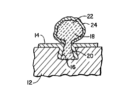
Figure 1 shows a cross-section of a portion of a heat exchanger fin
which has been prepared according to one embodiment of the present
invention. An anodizable metal substrate 12 such as aluminum or titanium
has an unse~le~, porous anodic oxide layer 14 formed therein with a pore
being shown at 16. Electrolytically deposited base metal, such as copper
or chromium, is deposited in the pore 16 to form the nodule designated 18
having a root portion 20 in the pore 16 and a head portion 22 extending
above the pore 16 and above the anodic oxide layer 14. Deposited onto
the head portion 22 is a coating of the catalyst metal 24 such as platinum.
Other examples of catalyst metals which could be used include palladium,
ruthenium, rhodium and other noble metals as well as rare earth metals.
The process of the present invention can be carried out batchwise
on plate material or alternatively carried out continuously using a metal
web of a suitable thickness which is continuously anodized, plated with the
first metal if desired, and plated with the catalyst metal. The formation of
the anodic oxide coating and the deposition of the metal into the pores of
the anodic oxide coating can be accomplished using the known techniques
as described in the previously mentioned U.S. Patents 3,929,594 and
4,021,~i92. As taught by that prior art, various combinations and
arrangements of anodizing cells, contact cells and plating cells can be
employed. Figure 2 illustrates one of these possible arrangements merely
as an example. In the following description, an aluminum web, copper
base metal nodules and platinum catalyst metal coating will be used as an
example, but it is to be recognized that other materials such as those
previously mentioned can be employed.
The aluminum web substrate 12 is first fed into the anodizing cell
26 having a cathode 28 connected to a source of direct current 30 and
containing a standard anodizing electrolyte bath. The anodizing direct
current from the source 30 is p~sed into the aluminum web through the
anode 32 in the contact and plating cell 34. Alternately, the anodizing
CA 02237010 1998-0~-07
W O 97/17483 PCTrUS96/17867
current can be passed into the web by means of a contact rolier such as
illustrated in the prior patents 3,929,594 and 4,014,756.
Once the anodic oxide layer has been formed on the web in the cell
26, the anodized web is passed to the contact and plating cell 34. In this
cell 34 the anode 32 is the platable metal selected for the base of the
nodule to be formed, such as copper or chromium. The cell contains an
appropriate electrolyte and the anode 32 is connected to the source 30 of
direct current power as stated above.
In the plating cell 34, the platable metal from the anode is deposited
in the pores of the anodic oxide layer which first forms the root 20 of the
nodule as illustrated in Figure 1. The plating operation is continued for the
length of time required to deposit the amount of base metal necessary to
form the nodule 18 including the head portion 22 of the desired size. At
this point, the web is removed from the plating cell 34 and introduced into
the next plating cell 36.
Plating cell 36 contains an appropriate electrolyte and the anode 38
which is a pl~t~hl~ catalytic metal such as platinum or one of the other
catalyst metals previously mentioned. The anode 38 is connected to the
direct current power source 40 which is also connected to the cathode 42
in the contact cell 44. The metal from the anode 38 is now deposited on
the surface of the nodules that had been formed in piating cell 34 to form
the catalyst metal coating 24 illustrated in Figure 1. After the desired
thickness of catalyst metal has been deposited, the web is removed from
the cell 44 after which it may be washed or otherwise treated as
appropriate. The resultant product is a web of aluminum with an anodic
oxide coating and the attached nodules of the first metal coated with a thin
layer of catalytic metal extending above the anodic oxide coating. This
web is then cut and shaped as required for forming the catalytic fins for
the heat exchanger of the present invention.
The present invention permits the control of the population density
of the catalyst nodules on the anodized substrate. Although the anodic
oxide coating on a roughened metal substrate is of uniform thickness, the
CA 02237010 1998-0~-07
WO 97/17483 PCTAUS96/17867
electrodeposition of a metal into the pores of the oxide will be initiated
prçferentially at the high points of the surface. At lower voltages, the
plating process is more selective and the tendency is that only the pores
at the high points will preferentially participate in the plating process with
less plating in the pores in the valleys. As this voltage is increased, the
plating process becomes less selective and the number of pores acting as
seeding sites increases. Therefore, the population of seeding sites and
nodules formed can be controlled by the voltage. Also, since the plating
begins first on the peaks, the degree of asperity or vertical height
difference between the valleys where there is little catalyst and the peaks
where there is more catalyst can be controlled. The more asperity
desired, the more the substrate is roughened and the lower the voltage
used.
As previously indicated, the nodules may be formed with a first
metal, such as copper, and then coated with the catalyst metal as has
been described thus far, or the nodules can be formed entirely of the
catalyst metal. Figure 3 is an enlarged cross-sectional view, similar to
Figure 1, which illustrates such a nodule. Shown in this Figure 3 is the
metal substrate 12, the porous anodic oxide layer 14, pore 16 and the
nodule 18 with the root portion 20 and the head portion 22. In this case,
the entire nodule 18 is formed of the catalyst metal, such as platinum, and
there is no nodule coating 24 as in Figure 1. With respect to the process
as shown in Figure 2, there would be only one plating cell instead of two.
Figure 4 illustrates a further variation of the present invention
~5 wherein the entire surface of the web or plate is coated with catalyst. In
this variation, the nodules can be initially formed from a first metal, such
as copper, or the entire electrodeposition can be with the catalyst metal as
shown in this Figure 4. In either case, the deposition of the metal begins
in the pores and tends to create the discrete nodules. However, the
electrodeposition is continued such that the metal builds-up and eventually
bridges over from one nodule to another generally as illustrated.
,
CA 022370l0 l998-0~-07
W O 97/17483 PCTrUS96/17867
Figure 5 illustrates an example of a portion of a heat exchanger
which has been constructed according to the present invention in which
the heat exchanger fins contain the catalyst material as has been
described. Illustrated is an automotive radiator 52 comprising upper and
lower chambers or headers 54 and 56, fluid flow tubes 58 connected
between the headers 54 and 56 and the parallel spaced fins 60. The
tubes 58 extend through apertures formed in the fins 60 with the fins being
connected to the tubes by conventional methods to provide good heat
transfer as well as a rigid mechanical structure. This Figure 5 iS merely
one example of a heat exchanger constructed according to the present
invention and it is to be recognized that the invention can be applied to
any finned tube heat exchange structure. Also by way of example,
reference is made to prior U.S. Patents 3,693,710; 4,327,800 and
4,601,089 illustrating various ways in which heat exchanger tubes and fins
can be assembled into a heat exchanger. Any of these or other assembly
techniques could be used in the present invention to assemble the catalytic
fin material to heat exchanger tubes.
The present invention lends itself to the formation of heat
exchangers with a mixture of different catalytic materials. A variety of fin
stocks can be prepared each containing a different catalyst. For example,
a platinum catalyst fin stock and a rhodium catalyst fin stock could be
formed into fins and then alternately assembled into the heat exchange
tubes or assembled in any desired order and proportion.
In an alternate embodiment of the present invention, the metal
surface containing the catalyst material is not formed as the integral heat
exchanger fins assembled onto the heat exchanger fluid flow tubes. This
embodiment would be particularly useful for situations where it would not
be practical or possibl~ to attach the catalytic fins to the heat exchanger
tubes to form a good heat transfer contact due to the high temperature
' 30 required for certain such operations. Instead, a separate structure is
formed which is constructed of catalytic material formed according to the
present invention. The structure may take any desired configuration such
-
CA 02237010 l99X-0~-07
W O 97/17483 PCT~US96/17867
as a grid structure formed of flat fin-like elements or a screen or wire mesh
structure. .For example, an aluminum wire may be treated in accordance
with the present invention to form the catalytic nodules thereon and then
the wire can be woven into a catalytic screen. In the alternative, the wire
5 could be woven into an aluminum screen first and then the catalyst formed
on a web of the screen material just as previously described for the solid
aluminum web. A further alternative would be to use fine catalytic wire
which is formed in a random arrangement into a mesh much like steel
wool. In any case, the catalytic structure is constructed and located such
10 that the air to be treated flows through the structure. The structure is
preferably located directly adjacent to and downstream from the heat
exchanger with respect to the direction of air flow so that the air flowing
over and through the catalytic structure is air that first comes through and
is heated by the heat exchanger. Also, the separate catalytic structure
16 could be employed even when the heat exchanger does contain catalyst
in order to increase the catalyst surface area.
Figure 6 shows such an arrangement wherein a separate catalytic
structure 62 is formed as a grid and mounted adjacent to the automotive
radiator 52 by the mounting straps 64. In this case, the automotive
20 radiator 52 need not contain catalytic fins although it may. The grid 62
comprises an outside frame 66 in which are mounted the catalytic fins 68
in an "egg-crate" configuration although the fins could be arranged within
the frame 66 in any desired configuration. As with the heat exchanger, fin
stock with different catalytic materials can be mixed in any desired
25 combination. The arrow 70 indicates the direction of air flow showing that
the air p~-sses through the radiator 52 first and is heated prior to passing
through the catalytic grid 62. This heating of the air enhances the desired
catalytic reactions. Also, the juxtaposition of the grid and radiator means
that the automotive fan which draws air through the radiator will also draw
30 that same air through the grid. The spacing of the fins in the grid as
iltustrated in this Figure 6, as well as the spacing in the radiator in Figure
5, is merely for illustrative purposes. The actual spacing would be much
CA 02237010 1998-0~-07
W O 97/17483 PCT~US96/17867
closer as in a conventional radiator or air conditioning condenser. One of
the advantages of this separate catalytic structure is that it can be easily
manipulated. For example, it can easily be detached from the heat
exchanger for cleaning or replacement. In addition, the separate catalytic
5 structure can be located in an air stream other than at the outlet of the
heat exchanger (radiator or air conditioning condenser). This might be
desired if it were not required that a heated environment be provided.
The catalytic stock produced according to the present invention
lends itself to the fabrication techniques required to form fins, wires or
10 other structural forms. It is resistant to mechanical shock and does not
result in a brittle coating which could be damaged during fabrication. This
invention is also suited to the use of titanium or aluminum bonded to steel
where structural strength is a prerequisite. It may be further desirable to
treat the aluminum bonded to steel such that the aluminum oxide is
15 converted to the more catalytically active gamma form. This treatment can
be accomplished, for example, by calcination at temperatures above
300~C. In this way, a multifunctional catalyst is obtained containing both
the metal catalyst nodules (or their oxide) and the gamma alumina.