Note: Descriptions are shown in the official language in which they were submitted.
CA 02237227 1998-06-11
APPARATUS 1?01~ STORAGE AND USE OF RO~,T,F,T)
TOBACCO PRODUCTS
Inventor: Kenneth L. Cigler
Field of the Invention
This disclosure concerns an invention relating generally to apparata for storageand use of rolled tobacco products such as cigarettes and cigars, and more specifically
to apparata for storing rolled tobacco products, providing means for lighting the rolled
tobacco products, and also providing means for clipping rolled tobacco products along
S their lengths.
Background of the Invention
A number of prior apparata exist for cutting rolled tobacco products (such as
cigarettes and cigars) along their lengths for the purpose of providing neatly trimmed
ends to serve as mouthpieces for smoking purposes, or to recondition previously ignited
ends for later re-lighting. Other apparata have been provided for storing rolled tobacco
products in combination with implements for lighting the products. However, all known
apparata suffer from disadvantages in terms of their ease of use, and they are also not
well suited for storage and transportation in one's pocket or purse to allow portable use.
Summary of the Invention
The invention, which is defined by the claims set out at the end of this
disclosure, may be embodied in a variety of different structures. A particularlypreferred embodiment of the apparatus has a housing including walls definin~ a clipping
apellure. The clipping aperture is at least partially bounded by a sharp edge, and a
cutting door is movably attached to the housing so as to move over the clipping
aperture, thereby opening and closing the clipping aperture and forcing any rolled
tobacco products inserted within the clipping aperture against the sharp edge to cut the
products along their lengths. A lighter is integrally or removably incorporated within
CA 02237227 1998-06-11
the housing so that the base of the lighter is situated adjacent the clipping aperture. The
cutting door is preferably spring-biased to maintain it in a normally closed state, and if
desired, the sharp edge which cuts the rolled tobacco products may be Cit~l~tY~ on the
cutting door. The cutting door is preferably constrained by the housing to slide along
S a path situated along at least a portion of the length of the lighter.
The preferred embodiment of the apparatus also includes walls within the
housing which define an elongated rolled tobacco products cavity so that a rolled
tobacco products receptacle is provided. A cap may be provided to close the rolled
tobacco products cavity, and the cap is preferably movably affixed to the housing and
is spring-biased to keep the rolled tobacco products cavity in a normally closed state.
The same spring used to bias the cutting door into a closed position over the clipping
aperture may be used to bias the cap over the rolled tobacco products cavity.
The preferred embodiment of the apparatus also includes walls defining a refuse
cavity adjacent the clipping aperture, thereby providing a refuse receptacle wherein
cuttings from rolled tobacco products cut by the cutting door may be received and
stored. The housing may also include an access door opening onto the refuse cavity to
allow cleaning and emptying of the refuse cavity, though a user may instead clean and
empty the refuse cavity by accessing it via the cutting door.
In the ~lefelled embodiment of the apparatus, the refuse cavity is preferably
sihl~ted adjacent the base of the lighter and along a lengthwise axis of the lighter cavity.
The rolled tobacco products cavity is preferably adjacent the lighter cavity and is
preferably aligned generally parallel to the lighter cavity. The cutting door may be
situated between the walls defining the lighter cavity and the walls defining the rolled
tobacco products cavity so that it slides therebetween, and also over the clipping
aperture.
The most preferred embodiment of the apparatus is compact and easily stored in
a pocket or purse; it combines two or more of a lighter receptacle, a rolled tobacco
products receptacle, and a rolled tobacco products cutter in a highly space-efficient
manner for convenient use; it retains rolled tobacco products in a substantially air and
water-tight receptacle to prevent damage or soiling of the products, or the escape of
-2 -
CA 02237227 1998-06-11
odors from the products; it automatically closes the tobacco products receptacle to
prevent accidental release of (and damage to) the tobacco products; it retains cuttings
for later emptying to prevent littering; it autom~tic~lly closes the cutting door to
prevent emptying of cuttings into a user's pocket; it provides a cutting door which acts
S in a direction parallel to the walls of the lighter receptacle, thereby allowing much of
the cutting door mechanism to reside within the walls of the apparatus to save space;
it retains the cuttings in a substantially air-tight receptacle to prevent the release of
odors; it provides an access door to the cuttings receptacle with a unique ~çt~l~ting
mechanism requiring both linear and rotational motion to open the access door, thereby
reducing the possibility that cuttings may accidentally empty into one's pocket or purse;
and it allows the storage and transport of only so many rolled tobacco products as the
user desires, rather than packages of products in bulk amounts.
Further advantages, features, and objects of the invention will be apparent fromthe following detailed description of the invention in conjunction with the associated
drawings.
Brief Description of the Drawings
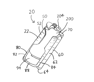
~IG. 1 is a front perspective view of an apparatus embodying a particularly
preferred form of the invention.
FIG. 2 is a front perspective view of the apparatus of ~IG. 1, but wherein the
lighter (200) is shown removed, and further wherein the access door (94) of the refuse
section (80) and the cap (70) of the rolled tobacco products section (60) are shown in
an open state.
~fG. 3 is a rear perspective view of the apparatus of FIGS. 1-2 wherein the
cutting door (92) and the cap (70) of the rolled tobacco products section (60) are shown
in an open state.
~IG. 4 is a rear perspective view of the apparatus of ~IGS. 1-3 wherein the
cutting door (92) and the cap (70) of the rolled tobacco products section (60) are shown
in a closed state.
CA 02237227 1998-06-11
FIG. 5 is a partial top plan view of the apparatus of FIGS. 1-4.
FIG. 6 is a partial front elevation view of the apparatus of FIGS. 1-5.
~G. 7 is an exploded partial rear elevation view of the apparatus of ~IGS. 1-6.
FIG. 8 is an exploded partial side elevation view of the apparatus of ~IGS. 1-7.S ~IG. 9 is a top plan view of the access door (94) of FIGS. 1, 2, and 8.
FIG. 10 is a rear elevation view of the access door (94) of FIGS. 1, 2, 8, and
9.
~IG. 11 is a side elevation view of the finger actuator (104) of F~GS. 3 and 4.
FIG. 12 is a bottom plan view of the finger actuator (104) of FIGS. 3, 4, and
11.
FIG. 13 is a side elevation view of the f1nger actuator (104) of ~IGS. 3, 4, 11,and 12.
FIG. 14 is a side elevation view of the cutting blade (96) of the cutting door (92)
of FIGS. 3 and 4.
~IG. 15 is a side elevation view of the wedge (100) of the cutting door (92) of
FIGS. 3, 4, 6, and 7.
Detailed Description of Preferred Embodiments of the Invention
In the drawings, wherein the same or similar fealults of the invention are
designated in all Figures with the same reference numerals, ~IGS. 1~ illustrate the
entirety of a particularly preferred embodiment of the apparatus at the reference numeral
20. The apparatus 20 includes a housing n which preferably includes three sections:
a lighter section 50 including walls 52 and 54 defining an elongated lighter cavity 56
wherein a lighter 200 may be removably inserted (see particularly ~IG. 2); a rolled
tobacco products section 60, which includes walls 62 and 64 defining an elongated
rolled tobacco products cavity 66 (see particularly FIG. 3); and a refuse section 80
which includes walls 82, 84, 86 and 88 defining a clipping aperture 90 (see particularly
FIGS. 2-4), and a cutting door 92 constrained to move over the clipping aperture 90 to
open and close the clipping aperture 90 and cut rolled tobacco products inserted therein.
CA 02237227 1998-06-11
Each of the lighter section 50, the rolled tobacco products section 60, and the refuse
section 80 will now be discussed in tu~
Within the housing 22, the lighter section 50 is intended to accommodate a well-known lighter 200, which has a lighter base 202 at one end of its longitudin~l axis and
a lighter tip 204 at the opposite end from which the lighting flame is emitted. The
lighter section 50 is most clearly illustrated in FIG. 2, wherein the lighter 200 is shown
removed from the lighter cavity 56. Surrounding the lighter cavity 56, lighter section
side walls 52 extend about the longitudinal circumference of the lighter 200 in
complimentary fashion so that the lighter 200 can be tightly received therein with a
sufficiently close fit that the lighter 200 is restrained from slipping out of the lighter
cavity 56, but the lighter 200 may nevertheless be easily removed and replaced when
desired. The lighter section side walls 52 provide sufficient clearance about the lighter
tip 204 that no significant amount of heat is transmitted from the lighter tip 204 to the
lighter section side walls 52, and additionally any flame actuators or other lighter
controls at the lighter tip 204 are exposed for easy use. Removal of the lighter 200 can
be eased somewhat by partially cutting away the lighter section side walls 52, as FIGS.
1-2 illustrate, but the side walls 52 may continuously extend about some or all of the
longitude and circumference of the lighter 200 as desired. A base wall 54 (see
particularly ~IG. 2) bounds one end of the length of the lighter cavity 56 to provide a
surface which the lighter base 202 may abut when the lighter 200 is inserted within the
lighter cavity 56. Adjacent the base wall 54 is an openable access door 94 (see
particularly FIGS. 1 and 2) -- which will be discussed at greater below -- which allows
access to the interior of the refuse section 80 and which also abuts a portion of the
lighter base 202 when the lighter 200 is inserted within the lighter cavity 56. Thus, as
~IG. 2 illustrates, a portion of the lighter base 202 is exposed when the access door 94
is opened, and is available for the user to push if the user experiences difficulty in
removing the lighter 200 from the lighter cavity 56.
The rolled tobacco products section 60 is best viewed with initial reference to
FIGS. 1-4. The rolled tobacco products section 60 includes products section side walls
_5
CA 02237227 1998-06-11
62 and a products section bottom wall 64 defining a rolled tobacco products cavity 66
(see FIGS. 3 and 5-8) having a opening 68, and a cap 70 which may be disposed over
the opening 68 to close the products cavity 66. In the embodiment of the apparatus 20
illustrated in the Figures, the rolled tobacco products cavity 66 is sized to contain a
single rolled tobacco product, e.g., a cigarette, and is aligned generally parallel to the
lighter cavity 56/lighter 200 in order to conserve space. As is best seen from FIG. 5,
the products cavity is also slightly offset from a plane which bisects the lighter cavity
56/lighter 200 and which is also coincident with the major axis of the lighter cavity
56/lighter 200. Conveniently, the lighter section 50 and rolled tobacco products section
60 are aligned so that the user may grasp the apparatus 20 in one hand, open the cap
70 by use of the thumb, lift the apparatus 20 to the lips to receive the rolled tobacco
product, and then actuate the lighter 200 using the same hand.
While a removable cap or simple hingedly actuable cap could be used to allow
selective access to the products cavity 66, the most preferred embodiment of theapparatus 20 has a hingedly actuable cap which is spring-biased to m~int~in the products
cavity opening 68 closed until the cap 70 is pushed away from the opening 68, and
which then closes the opening 68 when the pushing force is removed. With reference
to ~IGS. 5-8, a passage 24 is defined in the housing 22 adjacent the lighter section side
walls 52 surrounding the lighter cavity 56. A spring 26 (shown in FIG. 7) may bedisposed in the passage 24 and a first spring end 28 distant from the opening 68 may
be anchored against rotational movement by use of an anchoring means. In the
preferred embodiment of the apparatus 20, this anchoring means takes the form of an
anchoring member 30 which inserts within the coils of the spring 26 and which provides
a corrugated surface 32 at the first spring end 28 which mates with a cutting blade 96
in the cutting door 92 in complimentary fashion (as will be discussed at greater length
below). This restrains the spring 26 from rotational movement once the anchoringmember 30 is affixed to the spring 26 by brazing or other forms of affixment. A pivot
rod 34 is similarly affixed to a second end 36 of the spring 26 closest to the opening 68,
and the pivot rod 34 similarly provides a corrugated surface 38 at the second end 36 of
the spring 26.
-6-
CA 02237227 1998-06-11
The cap 70 is then provided with first and second collet members 72 and 74 at
its side, the first collet member 72 non-fixably receiving the pivot rod 34 therein and
the second collet member 74 having a corrugated interior surface 76 complim~ntary to
the corrugated surface 38 at the end of the pivot rod 34 to fixably receive the end of the
s pivot rod 34. As is best seen with reference to ~GS. 3, 4, 6, and 7, portions of the
housing 22 along the passage 24 are cut away to provide a first aperture 40 for receiving
the first collet member 72 and a second aperture 42 for receiving the second collet
member 74. Thus, the spring 26 (and its associated anchor member 30 and pivot rod
34) may be inserted within the passage 24 and the spring 26 may be coln~lessed so that
the corrugated surface 38 of the pivot rod 34 clears the first aperture 40. The first and
second collet members 72 and 74 may then be inserted within their respective first and
second apertures 40 and 42, and decompression of the spring 26 then causes the pivot
rod 34 to move upwardly into the collet members 72 and 74 until its corrugated surface
38 engages and locks within the corrugated interior surface 76 of the second collet
member 74. The cap 70 is thus restrained atop the products cavity 66 with the spring
26 serving as a torsion spring to maintain the cap 70 in a closed position over the
products cavity 66 (as illustrated in ~IGS. 1 and 4). By pushing the cap 70 sideways,
it may be pivoted open about the pivot rod 34 as illustrated in F~GS. 2 and 3.
The refuse section 80 of the housing 22 is best visu~li7ed with reference to
FIGS. 1, 2, and 6-8. The refuse section side walls 82 and 84 and refuse section top
and bottom walls 86 and 88 define the clipping aperture 90 adjacent the base wall S4
of the lighter cavity 56. Ideally, the sizing of the walls 82 and 84 of the clipping
aperture causes the refuse section 80 and lighter section 50 combined to occupy roughly
the length of a standard rolled tobacco product (e.g., cigarette). For a highly space-
efficient arrangement, it is also preferable that the refuse section side walls 82 and 84
be generally contiguous with the lighter section side walls 52 so that the refuse section
80 in general rests at least substantially within the boundaries of the extended lighter
section side walls 52 (i.e., so that the refuse section 80 rests wholly or in substantial
part within the boundaries of said lighter section side walls 52 if they were extended
CA 02237227 1998-06-11
longitudinally along the axis of lighter 200). In this manner, the refuse section 80
appears to exist as an extension of the lighter section 50 and it does not have the "look
and feel" of occupying significant additional space. Preferably, at least one side of the
clipping aperture 90 is bounded by a sharp edge 98, and in the appalat~ls 20 illustrated
in the Figures this is done by inserting a sharpened metal wedge 100 into a slot 102 in
the housing 22 (best seen in FIG. 5) so that the wedge 100 partially closes the clipping
aperture 90, with its sharp edge 98 exposed. The cutting door 92 incll1des the sharp
cutting blade 96 and additionally includes a finger actuator 104. The cutting blade 96
of the cutting door 92 may thus be moved by use of the finger achl~tor to close the
clipping aperture 90 so that the sharpened edge of the cutting blade 96 abuts the wedge
100 to shear and cut any rolled tobacco products inserted within the clipping aperture
90 (see particularly FIGS. 3 and 4). As is best seen from ~G. 14, the cutting blade
96 is configured to slidably fit within the slot 102 (again refer to ~IG. 5) so that the
cutting blade 96 is movably attached to the housing 22 and is constrained to slidably
move over the clipping aperture 90 and thereby open and close the clipping apelLul~ 90.
The cutting blade 96 also includes a receiving surface 106 upon which the anchoring
member 30 is received when the spring 26/pivot rod 34/anchoring member 30
combination is inserted within the passage 24 in the housing 22, as ~ clJssed above.
Thus, when the first and second collet members 72 and 74 of the cap 70 are inserted
within the a~~ r~s 40 and 42 in the housing 22 to restrain the longihl-lin~l motion of
the spring 26 and to bias the cap 70 closed, the spring 26 also biases the cutting blade
96 to maintain the clipping aperture 90 in a normally closed state.
The finger actuator 104 is then illustrated in FIGS. 11-13 at various angles. The
finger actuator 104 is preferably affixed to the cutting blade 96 by e~t~-n~in~ screws
through a~el~ur~s 108 in the cutting blade 96 (see FIG. 14) and into the finger actuator
104, though other means of affixment may be used instead. As noted above, and asshown particularly in FIG. 5, the walls 62/64 of the rolled tobacco products section 60
are slightly offset from the width-wise axis of the lighter section 50 so that a slight
concavity is formed between the rolled tobacco products section 60 and the lighter
CA 02237227 1998-06-11
section 50. As is best shown by FIGS. 3 and 4, the cutting door 92 (i.e., the finger
actuator 104 and cutting blade 96) slides within this concavity. This helps to save space
and also helps deter inadvertent actuation of the cutting door 92 within a purse or pocket
owing to contact of a protruding finger actuator 104 with other objects. Si~nifit~nt
space savings is also achieved by constraining the cutting door 92 to move generally
parallel to the housing 22, and additionally by movably attaching the cutting door 92
within the housing 22 with its path of travel extending outside of the refuse section 80
and adjacent the rolled tobacco products section 60 and the lighter section 50 because
no significant additional space beyond that which is already occupied by the product
section, lighter section 50, and refuse section 80is utilized to accommodate the cutting
mechanism.
Adjacent the clipping aperture 90, the refuse section side walls 82 and 84 and
top and bottom walls 86 and 88 are preferably closed so as to define a refuse cavity 110
within the refuse section 80 wherein cut portions of rolled tobacco products may be
lS stored. An immobile wall may be used to close the refuse cavity 110, but as will be
discussed below and as is illustrated in FIG. 2, the refuse cavity 110 is preferably
closed by the openable access door 94 in the refuse section 80 to allow easier access to
the refuse cavity 110. In either case, refuse may be emptied from the refuse cavity 110
by actuating the finger actuator 104 to open the clipping aperture 90, and then simply
emptying the refuse through the clipping aperture 90. The spring-biasing of the cuffing
door 92 to maintain the clipping aperture 90 in a normally closed state is advantageous
because it will prevent the inadvertent emptying of refuse into the user's pocket or
purse.
However, emptying of the refuse cavity 110 is significantly eased if the
aforementioned access door 94 is used to close the refuse cavity 110 rather than an
immobile wall. As illustrated in FIG. 2, it is preferable to have the aforementioned
access door 94 comprise an entire wall of the refuse cavity 110 so that access to the
entirety of the refuse cavity 110 is provided, thereby allowing more thorough emptying
and cleaning of the refuse cavity 110. The access door 94 preferably includes a land
112 which fits within the perimeter of the refuse cavity 110 in complimentary fashion,
CA 02237227 1998-06-11
and a door pin 114 extending into a pin passage 44 in the housing 22 adjacent the refuse
cavity 110 and extending from the opposite side of the housing 22 (see particularly
FIGS. 5-8). Thus, when the access door 94 is closed as illustrated in ~IG. 1, the door
pin 114 extends slightly from the opposite side of the housing 22 as illustrated in FIGS.
3 and 4. The door pin 114 fits so closely within the pin passage 44 that it is resistant
to longitudinal or rotational motion within the pin passage 44. This tight fit may either
be provided by use of a close friction fit, or as illustrated particularly in FIGS. 6 and
8, a rubber insert 46 may be inserted within an insert passage 48 adjacent the pin
passage 44 so that the insert bears against the door pin 114 to inhibit its motion. By
pushing on the end of the door pin 114 illustrated in ~GS. 3 and 4, the access door 94
will be moved slightly out of engagement with refuse section side walls 82/84 and top
and bottom walls 86/88 just so much as to form a crack between the access door 94 and
the refuse section walls, but not so much as to move the land 112 out of the refuse
cavity 110. With this crack formed, the user may grasp access door 94 to pull itoutwardly from the refuse cavity 110 in the direction of the longitu-lin~l axis of the door
pin 114 until the land 112 clears the refuse section walls 82184l86l88. The access door
94 may then be swung about the axis of the door pin 114 into the position ilhl$tr~ted in
~IG. 2 to allow access to the refuse cavity liO. Since the refuse cavity 110 will
contain tobacco particles and burnt and odiferous matter such as ashes and semi-burnt
tobacco (and perhaps even butts of smoked tobacco products if the refuse section 80 is
also used as an ashtray), it is desirable to make the refuse cavity 110 as resistant as
possible to inadvertent opening within one's pocket or purse. The access door 94 of
FIG. 1 is resistant to inadvertent opening in that the use of the land 112 and pin 114
requires motion in two degrees of freedom to gain access to the refuse cavity 110.
The apparatus 20 is preferably made of plastic, though it may instead be made
of cast or machined metal or ceramic material. It has a particularly attractive
appearance when made of cast gunmetal or machined stainless steel, and has the
appearance of a precision instrument, as well as impressive heft in the hand. If made
of metal, it is also an attractive option to integrally form a refillable lighter in place of
the lighter cavity 56 of the apparatus, though this may be done when the a~al~tus 20
-10-
- - -
CA 02237227 1998-06-11
is made of other materials as well. The use of metal also makes the apparatus 20attractive for monogram engraving, jewelled insets, and other types of decoration
popular in the jewelry arts.
It is notable that the cutting door 92 of the refuse section 80, when provided in
the same or similar form as that shown and described above, is believed to operate in
a far superior manner to any prior devices when used to cut off the burning portion of
a rolled tobacco product to recondition the product for later relighting and smoking. It
is known to smokers that relighting of a stubbed-out rolled tobacco product typically
renders the product foul-tasting and generally unsuitable for smoking when it is later
relit. The same effect occurs when rolled tobacco products are extinguished by inserting
them into elongated cavities so that their burning portions consume their surrounding
air supply, or by inserting them within such elongated cavities having cutting devices
therein. In contrast, the cutting door 92 and refuse section 80 described above has been
found to recondition rolled tobacco products with substantially reduced deterioration in
taste and smell. While the precise reason for this improved performance is not known,
it is believed to arise because prior to and during cutting, the apparatus 20 provides lit
rolled tobacco products with an adequate oxygen supply at all times. The reconditioned
portions of the rolled tobacco products are never placed in proximity to m~tPri~ls
burning in an atmosphere with an incomplete oxygen supply. It is believed that in the
prior art devices, the rolled tobacco products are extinguished in an atmosphere having
depleted oxygen, thereby leading to incomplete combustion and the release of foul-
tasting and foul-smelling particles which may be absorbed by the reconditioned portion
of the rolled tobacco products. Referring particularly to FIGS. 3 and 4, it is evident
that when rolled tobacco products have their burning portions inserted within the
clipping aperture 90 for removal by shutting the cutting door 92, the rolled tobacco
products will at all times be in a substantially open-air environment, and thus the portion
to be reconditioned will never be situated nearby materials undergoing incomplete
combustiom The burning particles are then retained and rapidly suffocated within the
closed refuse cavity 110, which is resistant to the release of odors, and the reconditioned
portion of the rolled tobacco product may be retained within the rolled tobacco products
CA 02237227 1998-06-11
section 60. Because the reconditioned rolled tobacco product has no significant
deterioration in taste and odor, it is no longer objecticnable to relight reconditioned
products.
The apparatus 20 is also useful when a user is attempting to quit smoking. The
user can smoke just so much of a cigarette to satisfy a nicotine craving, then cut off the
burnt end using the cutting door 92 and place the remainder of the cigarette in the rolled
tobacco products cavity 66. The remainder of the cigarette can then later be removed
and relit for use, and again only so much can be smoked as is necess~ry to satisfy a
craving. In this manner, use of a single cigarette can be extended to take the place of
several, and one's total cigarette consumption will overall be decreased.
While the apparatus 20 is illustrated and described above as being particularly
suited for use with rolled tobacco products such as cigarettes, it is easily adaptable by
one of ordinary skill for use with cigars. It is understood that the various preferred
embodiments are shown and described above to illustrate different possible features of
the invention and the varying ways in which these features may be combined. Apart
from combining the different features of the above embodiments in varying ways, other
modifications are also considered to be within the scope of the invention. Following is
an exemplary list of such modifications.
First, if desired, the cutting blade 96 and finger actuator 104 may be omitted
from the clipping aperture 90 and replaced with a wall, and the access door 94 can be
used to serve as the cutting door. This can be done by providing the clipping aperture
90 with a sharp edge provided on the refuse section side walls 82/84 and/or top or
bottom wall 86/88 of the refuse cavity 110, and/or on the edge(s) of the access door 94
adjacent the clipping aperture 90, so that closing of the access door 94 on a rolled
tobacco product will cut it.
Second, the means for allowing the cap 70 to pivot away from the rolled tobacco
products cavity 66 may not be provided in the exact form shown, and for example the
pivot rod 34/anchor member 30 could be deleted if the spring 26 is attached directly to
the cap 70, cutting blade 96, and/or housing 22. Different torsion and compression
members apart from a helical spring may be used. Further, separate torsion and
-12-
CA 02237227 1998-06-11
compression members could be provided to separately actuate the cap 70 and the cutting
blade 96.
Third, as noted above, both the cutting blade 96 and the wedge _ are described
as including sharp edges. It is understood that only one of the cutting blade 96 and the
wedge 100 need bear a sharp edge since closure of the cutting blade 96 will in any case
force the rolled tobacco product against a sharp edge to sever the rolled tobacco
product. However, the use of a sharp edge on both the cutting blade 96 and the wedge
100 helps to insure that an especially clean cut is created. Further, while the preferred
apparatus 20 causes the cutting blade 96 and the wedge 100 to travel alongside each
other to cut the rolled tobacco product, direct edge-to-edge meeting of the cutting blade
96 and wedge 100 is also possible. It is also possible to elimin~te the wedge 100
entirely and to simply have the sharp edge of the cutting blade 96 bear down on the
rolled tobacco product with the bottom wall 88 of the refuse section 80 restraining the
rolled tobacco product from movement.
Fourth, the aforementioned arrangement and ~limen~ioning of the lighter section
50, rolled tobacco products section 60, and refuse section 80 (including the cutting door
92/104) are believed to provide a particularly convenient and space-efficient
arrangement of elements which is well suited for'one-handed use of the various sections
and easy storage. However, the various elements of the apparatus 20 can in some cases
be differently dimensioned and/or rearranged in various fashions without significant
adverse effects on the advantages of the preferred embodiment of the invention. As an
example, if desired, the rolled tobacco products section 60 may be made slightly longer
so that its cap 70 is roughly flush with (or extends slightly beyond) the tip of the lighter.
This may be desirable if carrying the apparatus 20 within a pocket or purse and contact
with the lighter tip 204 is undesirable owing to the possibility of inadvertent actuation
or potential catching of the lighter tip 204 on the interior of the purse or pocket. As
another example, the refuse section 80 could have a larger size and could rest
intermediate the lighter section 50 and rolled tobacco products section 60. The refuse
cavity 110 may then be sized so that when the access door 94 is open, the refuse cavity
-13-
- - -
CA 02237227 1998-06-11
110 may be used as an ashtray if desired so that ashes or leftover smoking m~eri~l~ can
be retained for later disposal without escape of odors.
Fifth, it is possible to have the rolled tobacco products cavity 66 be sized to
contain more than a single rolled tobacco product. As an example, the products cavity
66 may be sized large enough to contain up to 5 cigarettes. The user can then carry the
apparatus 20, rather than an entire pack of cigarettes, to limit the amount of cigarettes
available for smoking.
The invention is not intended to be limited to the plefelled embodiments
described above, but rather is intended to be limited only by the claims set out below.
Thus, the invention encompasses all alternate embodiments that fall literally orequivalently within the scope of these claims. It is understood that in the claims, means
plus function clauses are intended to encompass the structures described above as
performing their recited function, and also both structural equivalents and equivalent
structures. As an example, though a nail and a screw may not be structural equivalents
insofar as a nail employs a cylindrical surface to secure parts together whereas a screw
employs a helical surface, in the context of fastening parts, a nail and a screw are
equivalent structures.
-14-