Note: Descriptions are shown in the official language in which they were submitted.
CA 022372~0 1998-0~-08
Description
RECIPROCATING SLAT CONVEYORS
Technical Field
This invention relates to reciprocating slat conveyors. More particularly, it relates to
the provision of conveyor slats with a pressure seal system between adjoining slats formed
by the conveyor slats, that seals against passage of particulate material from a region above
the conveyor slats to a region below the conveyor slats.
Back~;round of the Invention
A typical conveyor slat, bearing, support beam and seal system is disclosed by my U.
S. Patent No. 5,303,816, granted April 19, 1994, and entitled Seal Strip for Reciprocating
Floor Conveyors. In this system, plastic bearings are snap-fitted onto longitudinal support
beams. The conveyor slats are snap-fitted onto the bearings. Each conveyor slat carries an
elastomeric seal member on one side that makes sealing contact with an adjacent side of an
adjoining conveyor slat. U. S. Patent No. 5,560,472, granted October 1, 1996, to Richard T.
Gist, discloses a conveyor slat, bearing, support beam, and seal system which elimin~tçs the
elastomeric seal members. In their place, longitudinal support beams are positioned laterally
between the conveyor slats. Upper portions of these support beams provide upwardly
directed, hard plastic, bearing/seal surfaces. The conveyor slats have upper side portions that
overhang the bearing/seal surfaces. These upper side portions of the conveyor slats include
depending, longitudinal beads that contact and ride on the bearing/seal surfaces. The weight
of the conveyor slats, and the weight of any load on the conveyor slats, is transmitted from
the conveyor slats to the longitudinal support beams. This weight transfer occurs where the
longitudinal slat beads contact and ride on the bearing/seal surfaces. The contact is a narrow
line contact. Because the contact occurs along a relatively narrow line, a substantial force is
generated which urges the longitudinal beads into a tight sealing contact with the bearing/seal
surfaces. However, also because contact occurs along a relatively narrow line the area of
contact is small resulting in the forces necessary to reciprocate the conveyor slats back and
forth along the support beams being smaller. At the same time, the contact is a tight contact
that effectively seals against passage of particulate material from a region above the conveyor
slats to a region below the conveyor slats.
APPS\Foster-CE ~ 1 ~
CA 022372~0 1998-0~-08
An object of the present invention is to provide a pressure seal system in which the
pressure seal is provided by contacting adjacent portions of adjoining conveyor slats. The
conveyor slats that transmit the load are guided by guide beams and are held in position
relative to the guide beams but without any weight transfer from these conveyor slats to the
guide beams. An advantage of making the bearing/seal surfaces a part of the conveyor slats
is that their construction and placement can be controlled at the factory as a part of the
manufacture of the conveyor slats. The installer need only install the longitudinal guide
beams, snap-fit bearings on some of the beams and install hold down members on the others.
It may also reduce costs because it reduces the amount of plastic material that is needed. In
the system disclosed by U. S. Patent No. 5,560,472, the members 30 and 56 are made from
a plastic material that has a low friction surface characteristic. These members are continuous
and are relatively large in cross-section in comparison with the bearing/seal rnembers, the
snap-on bearings and the hold down members that are utilized in at least some embodiments
of the present invention.
Disclosure of the Invention
The present invention is basically characterized by a first conveyor slat having a first
upper side portion and a second conveyor slat adjoining the first conveyor slat and also having
a first upper side portion. The first upper side portion of the first conveyor slat includes a
longitudinally extending bearing/seal member having an upwardly directed, hard plastic
bearing/seal surface. The first upper side portion of the second conveyor slat extends laterally
over the bearing/seal surface of the bearing/seal member. It includes a depending,
longitudinal support and seal bead. This bead has a lower edge that contacts and slides along
the bearing/seal surface of the bearing/seal member. This contact of the lower edge of the
bead with the bearing/seal surface seals against passage of particulate material from a region
above the conveyor slats to a region below the conveyor slats. The weight of the second
conveyor slat and the weight of the load on the second conveyor slat are transmitted
downwardly from the second conveyor slat to the first conveyor slat via contact of the bead
with the bearing/seal member.
In preferred form, the first conveyor slat has a second upper side portion that is like its
first upper side portion and the second conveyor slat has a second upper side portion that is
like its first upper side portion. Thus, the conveyor has two types of slats. The odd number
APPS\Foster-CE -2 -
CA 022372~0 1998-0~-08
slats are of a first type. The even number slats are of a second type. Herein, the odd number
slats are sometimes referred to as the alternate slats. The even number slats are sometimes
referred to as the intermediate slats.
In an embodiment of the invention, the second conveyor slat includes a top panelportion that is positioned laterally between its upper side portions. The upper side portions
of the second conveyor slat extend upwardly and outwardly from the top panel and then
laterally outwardly into a position over and covering the bearing/seal surfaces of the
bearing/seal members carried by the adjoining first conveyor slats. In this embodiment, the
first conveyor slat has a top panel portion that is positioned laterally between its first and
second upper side portions and such top panel portion is at a level below the level of the upper
side portions of the second conveyor slat.
In accordance with an aspect of the invention, longitudinal guide beams are provided
for the first and second conveyor slats. Bearings are provided on the longitudinal guide beam
for the first conveyor slat. The first conveyor slat is supported on these bearings. The weight
of the first conveyor slat and the weight of any load on the first conveyor slat are transmitted
downwardly from the first conveyor slat onto the bearings and from the bearings to the
longitudinal guide beam of the first conveyor slat. Hold down members are provided on the
longitudinal guide beam for the second conveyor slat. The hold down members each has a
portion that engages the longitudinal guide beam and a portion that engages the second
conveyor slat. There is no transfer of the weight of the second conveyor slat, or the weight
of a load on the second conveyor slat, from the second conveyor slat to the hold down
members. The weight of the second conveyor slat and the weight of the load on the second
conveyor slat are instead transmitted downwardly from the second conveyor slat to the first
conveyor slat via the contact of the depending bead on the second conveyor slat with the
bearing/seal member that is carried by the first conveyor slat. The hold down members
function to resist upward movement of the second conveyor slat up from its longitudinal guide
beam.
In a second embodiment, the first conveyor slat has a second upper side portion that is
like its first upper side portion and the second conveyor slat has a second upper side portion
that is like its first upper side portion. The first conveyor slat has a top panel portion that is
positioned laterally between its upper side portions. The bearing/seal members are positioned
APPS\Foster-CE -3 -
CA 022372~0 1998-0~-08
.
substantially directly laterally outwardly from this top panel portion. The second conveyor
slat includes a top panel portion that is positioned laterally between its upper side portions.
The top panel portion of the first conveyor slat and the top panel portion of the second
conveyor slat are substantially at the same level. The upper side portions of the second
conveyor slat extend upwardly from the top panel portion of the second conveyor slat and then
laterally outwardly into a position over and covering the bearing/seal surfaces of the
bearing/seal members. The upper side portions of the second conveyor slat have top surfaces
that are above the top panel portions of the first and second conveyor slats. They also have
outer edge surfaces that extend downwardly from such top surfaces towards outer side
boundaries of the top panel portion of the first conveyor slat.
Preferably, the first upper side portion of the first conveyor slat has a downwardly and
outwardly sloping edge surface that is laterally outwardly of where the lower edge of the
depending, longitudinal bead contacts the bearing/seal surface of the bearing/seal member.
This sloping edge surface facilitates movement of fines laterally outwardly from the region
of the bead. This feature minimi7~s the accumulation of fines on the bearing/seal surface.
In a further embodiment of the invention, the first conveyor slat has a second upper side
portion that is like its first upper side portion and the second conveyor slat has a second upper
side portion that is like its first upper side portion. The first conveyor slat has a top panel
portion that is positioned laterally between its first and second upper side portions. The
bearing/seal members are positioned below the level of the top panel portion of the first
conveyor slat. The second conveyor slat includes a top panel portion that is positioned
laterally between its upper side portions. The first and second upper side portions of the
second conveyor slat are substantially laterally outwardly extending continuations of the top
panel portions of the second conveyor slat. The lower edges of the depending, longitudinal
beams on the upper side portions of the second conveyor slat contact and ride the bearing/seal
surfaces on the upper side portions of the first conveyor slat. The top panel portion of the first
conveyor slat and the top panel and upper side portions of the second conveyor slat are all
substantially coplanar.
In another embodiment of the invention, the first conveyor slat has a second upper side
portion that is like the first upper side portion of the second conveyor slat. The second
conveyor slat has a second upper side portion that is like the first upper side portion of the first
APPS\Foster-CE -4 -
CA 022372~0 1998-0~-08
conveyor slat. In this embodiment, a plurality of pairs of first and second conveyor slats are
placed side-by-side, with the lower edge of the depending, longitudinal bead on one side of
each conveyor slat contacting and sliding along a bearing/seal surface on an adjoining
conveyor slat. An advantage of this embodiment is that it is only necessary to make one style
of conveyor slat.
Additional features, advantages and objects ofthe invention are described in the detailed
description of the best mode and preferred embodiments and/or inherent in the structures that
are illustrated and described. Such detailed descriptions, the drawings, and the claims which
follow are all parts of the description of the invention.
Brief Description of the Draw;n~
In the drawings, like element designations refer to like parts throughout, and:
Fig. 1 is an end view of four adjoining conveyor slats, showing a first embodiment of
the invention;
Fig. 2 is a view like Fig. 1 but showing a second embodiment of the invention;
Fig. 3 is an end view of the alternate conveyor slats shown in Fig. l;
Fig. 4 is an end view of the intermediate conveyor slats shown in Fig. l;
Fig. 5 is an end view of the alternate conveyor slats shown in Fig. 2;
Fig. 6 is an end view of the intermediate conveyor slats shown in Fig. 2;
Fig. 7 is an enlarged scale fragmentary end view of adjacent side portions of adjoining
conveyor slats of a third embodiment of the invention;
Fig. 8 is a view like Fig. 7 but of a fourth embodiment of the invention; and
Fig. 9 is a fragmentary cross-sectional view of one full conveyor slat, its guide beam
and a bearing, and fragmentary portions of the two flanking conveyor slat/guide beam/bearing
assemblies, in a fifth embodiment of the invention.
Best Mode for Carrv;ng Out the Invention
A substantially complete reciprocating slat conveyor system is disclosed by my U. S.
PatentNo.5,165,524, grantedNovember 24,1992 and entitled Reciprocating Floor Conveyor.
Such patent discloses one suitable form of drive unit for reciprocating the conveyor slats.
Other suitable drive units, each having its own particular advantages, are disclosed by my U.
S. Patent No. 5,390,781, granted February 21, 1995, and entitled Mounting Assembly and
Method for Reciprocating Slat Conveyor, by my U. S. Patent No. Re. 35,022, granted August
APPS\Foster-CE - S -
CA 022372S0 1998-0~-08
22, 1995, and entitled Reduced Size Drive/Frame Assembly for a Reciprocating Floor
Conveyor, and by my U. S. Patent No. 5,605,221, granted February 25, 1997, and entitled
Drive Unit With Bearing Mount. The contents of these patents are hereby incorporated herein
by this specific reference.
My aforementioned U. S. Patent No. 5,165,524, with reference to Figs. 2-6 of that
patent, describes the most popular operational sequence of a reciprocating slat conveyor.
Figs. 7 and 8 of that patent show a typical framework that forms the base of the conveyor. It
includes opposite side beams (designated 12 in that patent) interconnected by a plurality of
longitudinally spaced apart transverse beams (designated 18 in that patent). Longitudinal
guide beams (designated 20 in that patent) are mounted on the transverse beams 18. Bearings
(designated 50 in that patent) are secured to the guide beams 20. The conveyor slats
(designated 40 in that patent) sit down on and engage the bearings 52. The present invention
relates to a similar arrangement of longitudinal guide beams, bearings and conveyor slats, but
involves a different construction of the conveyor slats and the bearing and seal structures that
are associated with the conveyor slats.
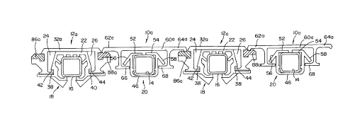
Referring to Figs. 1, 3 and 4, showing a first embodiment of the invention, the conveyor
slats of this embodiment are of two types. Every other slat, here the "odd number" or
"alternate" slats are designated 10. The in between slats, here the "even number" or
intermediate slats, are designated 12. Both types of slats 10, 12 are associated with
longitudinal guide beams 14, 16. Beams 14 are herein referred to as guide beams because
they only perform a guiding function. Beams 16 are herein referred to as guide and support
beams because they carry and transmit weight in addition to guiding the slats. Except for their
lateral spacing, the beams 14, 16 are like the beams that are designated 20 in my
aforementioned U. S. Patent No. 5,165,524. The beams 14, 16 extend longitudinally of the
conveyor and are secured to transverse frame beams, such as beams 18 shown in U. S. Patent
No. 5,165,524, or to some other suitable base structure.
Snap-on bearings 18 are longitudinally spaced along the guide and support beams 16,
where the beams 16 cross over the transverse frame beams. See for example Figs. 11 and 12
of my U. S. PatentNo. 4,785,929, grantedNovember 22, 1988, and entitled Bearing System
for Reciprocating Floor Conveyor. This patent is hereby incorporated herein by this specific
reference. U. S. Patent No. 4,785,929 presents a thorough illustration and description of the
APPS I oster-CE -6-
CA 022372~0 1998-0~-08
bearings 18. For that reason, the description of the bearings will not be repeated in this
document except for an identification of the major parts of the bearings 18. Each bearing 18
includes a top panel 22 that contacts its guide beam 16, opposite side portions 24, 26 that
depend downwardly from the top portion 22, and lower portions 28, 30. Figs. 7- 10 of U. S.
Patent No. 4,785,929 show how the bearings 18 are installed on the beams 16 and how the
conveyor slats 12 are installed on the bearings 18.
The conveyor slats 12 each include a top panel portion 32 and opposite upper side
portions 34, 36. The upper side portions 34, 36 extend downwardly from the top portion 32.
Each slat 12 has a lower side portion 34, 36, each including an inwardly directed flange 38,
40. When the conveyor slats 12 are installed, the top panel portions 32 of the conveyor slats
12 rest on and slide longitudinally along the top portions 22 of the bearings 18. The flanges
38, 40 of the conveyor slats 12 are received in longitudinal slots in the bearings 18 below lock
surfaces 42, 44.
For reasons that will be hereinafter described, the bearings 18 are not positioned on the
guide beams 14. Instead, the guide beams 14 are provided with a plurality of longitudinally
spaced apart hold down members 20 such as illustrated and described in detail in my U. S.
Patent No. 4,749,075, granted June 7, 1988, and entitled Hold Down Member for a
Reciprocating Floor Conveyor. The contents of U. S. Patent No. 4,749,075 is hereby
incorporated herein by this specific reference. Here, it will suffice to say that hold down
members 20 have bottom, side and top portions 46, 48, 50, 52, 54 which engage the guide
beams 14 and are installed onto them from below the guide beams 14. When installed, the
hold down members 20 provide laterally outwardly and dowllw~dly sloping lock flanges 56,
58.
Conveyor slats 10 have upper portions composed of a top panel 60 and a pair of
opposite upper side portions 62, 64. Conveyor slats 10 also have lower side portions that
depend from the regions where the top panel portion 60 meets the upper side portions 62, 64.
The lower side portions include inwardly directed flanges 66, 68. When the hold down
members 20 are installed on the guide beams 14, and when the conveyor slats 10 are installed
on hold down members, the lock flanges 56, 58 are positioned above the slat flanges 66, 68
in a position to block or restrain upward movement of the conveyor slats 10, in response to
APPS\Foster-CI~ 7
CA 022372~0 1998-0~-08
upward forces imposed on the conveyor slats. This is well illustrated and described in my
aforementioned U. S. Patent No. 4,749,075. See Fig. 7 of that patent, for example.
As shown by Fig. 3, the upper side portions 62, 64 of conveyor slat 10 are vertically
offset above the top panel portions 60. Diagonal transition walls 70, 72 extend upwardly and
outwardly from the top panel portion 60 to the upper side portions 62, 64. Transition walls
70, 72 have upper surfaces 74, 76 that slope upwardly and outwardly from the top panel
portions 60 to the upper side portions 62,64. These surfaces 74, 76 are edge surfaces and they
may be referred to as the inner edge surfaces of the upper side portions 62, 64. The upper side
portions 62, 64 also have outer edge surfaces 78, 80 that slope downwardly and outwardly
from the top surfaces 82, 84 of the upper side portions 62, 64. Preferably, the conveyor slats
10, 12 are extruded from an aluminum alloy, or some other metal, or a suitable structural
plastic. Or, they are formed by pultrusion and include longitudinally and laterally directed
fibers within a resin matrix. This construction forms the subject matter of my copending U.
S. Patent Application No. 08/832,370, filed April 12, 1997, and entitled Pultruded Conveyor
Slats. This application is hereby incorporated herein by this specific reference.
Referring to Fig. 4, the conveyor slats 12 are extruded to include longitudinal channels
82, 84 in which a hard plastic bearing/seal member is received and retained. The longitudinal
channels 82, 84, and the bearing/seal members 86, 88, form the upper side portions of the
conveyor slats 12. Bearing/seal members 86, 88 have upwardly directed bearing/seal surfaces
which may be substantially flush with the upper surface of top panel portion 42, or may be
elevated a slight distance above it, as illustrated in Fig. 4.
Each upper side portion 62, 64 is providing with a depending, longitudinally extending,
load carrying bead B, having a lower edge that contacts and rides on the upper surfaces 90,
92 of the bearing/seal members 86, 88. The lower edge may be relatively sharp, blunt or
rounded. Preferably, the beads B are the only portions of conveyor slats 10 that make a load
transmitting contact with the conveyor slats 12. Bearing/seal members 86, 88 may include
beveled outer edge surfaces 94,96 that slope outwardly and downwardly from the top surfaces
90, 92, respectively. The purpose of beveled edge surfaces 94, 96 is described later on in this
document.
As shown by Fig. 1, the upper side portions 62, 64 of the conveyor slats 12 rest on the
upper side portions of the conveyor slats 12. Specifically, the longitudinal beads B
APPS\Foster-CE ~ 8 -
CA 022372~0 1998-0~-08
substantially make a line contact with the bearing/seal surfaces 90, 92. The weight of the slats
10, and the weight of any load on the slats 10, is transmitted from conveyor slats 10 to
conveyor slats 12 by this contact of beads B to bearing/seal members 86, 82. There is always
a vertical space 98 between the top portions 52, 54 of the hold down members 20 and the top
panel portion 60 of the conveyor slats 10. Thus, there is no place other than where the beads
B contact the bearing/seal members 86, 88 for weight to be transmitted to some structure
below the conveyor slats 10. As previously described, the top panel portions 32 of the
conveyor slats 30 sit down on and ride along the top walls 22 of the bearings 18. The bearings
18 rest on the guide and support beams 16. Thus, the weight of conveyor slats 12, and any
load on the conveyor slats 12, including the load imposed by the contact occurring where the
beads B contact the surfaces 90, is transmitted from the conveyor slats 12 to the bearings 18
and from the bearings 18 to the longitudinal guide and support beams 16. Thus, in the manner
just described, the entire weight of the conveyor slats 10, 12, and any load on the conveyor
slats 10, 12, is transmitted to and carried by the longitudinal guide and support beams 16.
In the embodiment of Figs. 1,3 and 4, the top panel portion 60 of conveyor slat 10, the
bearing/seal members 86, 88, and the top panel portion 32 of conveyor slat 12 are all
substantially coplanar. The upper side portions 62, 64 of conveyor slats 10 are offset
vertically above the top panel portions 32, 60. They form what are in effect ridges that cover
the bearing/seal members 86, 88. The beveled edge surfaces 74, 76, 78, 80 provide the ridges
with relatively wide bases and relatively narrow tops. Conveyor slats 12 may include sloping
edge walls 98, 100 immediately laterally outwardly of the top panel portions 20. These edges
98, 100 are in effect continuations of the edge surfaces 78, 80.
The embodiment shown by Figs. 2, 5 and 6 differ from the embodiment disclosed byFigs. 1, 3 and 4 in that the upper side portions 62a, 64a of the conveyor slat lOa are
substantially coplanar with the top panel portion 60a and the top panel portion 32a. For this
to happen, the bearing/seal members 86a, 88a are offset below the top panel portions 32a.
This places the bearing/seal surfaces 90a, 92a at a level that is close to the level of the lower
surfaces of the top panel portions 32a, 60a, as best shown by Fig. 2. In this embodiment, the
beads B' are more in the nature of downwardly turned lips at the outer boundaries of the upper
side portions 62a, 64a. In this embodiment, the bearing/seal members 86a, 88a include
beveled outer edge surfaces 94a, 96a.
~PPS\Foster-CE ~9~
CA 022372~0 1998-0~-08
Fig. 7 illustrates a third embodiment of the invention. This embodiment is much like
the second embodiment. A key difference is that a lateral space or gap wl is provided
between the edge surfaces 80b,102. As illustrated, edge surfaces 80b, 102 slope downwardly
and outwardly from the tops of the conveyor slats lOb, 32b. In other words, the space
between the edge surfaces 80b, 102 converges from top to bottom. The narrow dimension,
designated wl in Fig. 7, is at least about one-fourth of an inch. In this embodiment, the bead
B' is essentially like bead B' in the embodiment of Figs. 2, 5 and 6. It has a laterally rounded
or somewhat blunt lower edge that contacts and rides on the bearing/seal surface 92b of
bearing/seal member 88b. The outwardly and downwardly sloping edge surface 96b on the
bearing/seal member 88b is a short distance laterally away from the contact of the bead B'
with bearing/seal surface 92b. As a result, any fines that migrate into the gap and find their
way between the bead B 1 and the bearing/seal surface 92b will, within a small distance, slide
or fall off of the edge surface 96b into the region below the conveyor slats lOb, 32b.
The embodiment shown by Fig. 8 is very similar to the embodiment shown by Fig. 7.
The difference is in the shape of the load transmitting bead B". In the embodiment of Fig.
7 (and also in the embodiment of Figs. 1, 5 and 6), the bead B' has downwardly converging
side surfaces that meet at a laterally rounded apex. In the Fig. 8 embodiment, the outside
surface of the bead B" is substantially vertical and the inside surface slopes downwardly and
outwardly to the apex. In this embodiment, the apex is shown to be laterally rounded. In
other embodiments, the converging surfaces (Fig. 7) or the vertical and sloping surfaces (Fig.
8) may come to a relatively sharp edge or apex, or may intersect a narrow blunt lower edge
surface. In all of the embo~limentri, the contact between the beads B, B ', B " is substantially
a line contact. The area of contact is relatively small. As a result, the friction forces are
relatively small even though the downward forces that promote sealing are relatively large.
Fig. 9 discloses a fifth embodiment of the invention. In this embodiment there is only
one type of conveyor slat 106. Each conveyor slat has a top panel portion 108 that is laterally
between upper side portions 110, 112. Upper side portions 110 may be like the side portions
on conveyor slats 12, 12a, 12b, 12c. These upper side portions include bearing/seal members
114 having upwardly directed bearing/seal surfaces 116. The opposite upper side portions of
these conveyor slats 106 are like the upper side portions 62, 64, 62a, 64a, 62b, 64b of the first
four embodiments. They each include a depending, longitudinal, load transmitting bead B"'.
APPS\Foster-CE ~ 10-
CA 022372~0 1998-0~-08
In this embodiment the bead B " ' is shown to have a relatively sharp lower edge that is contact
with the bearing/seal surface 116. An advantage of this embodiment is that it requires only
one style of conveyor slat.
The bearings 18 include side wings W which are below lower side edge portions 120,
122 of the conveyor slats 106. As described in my aforementioned U. S. Patent No.
4,785,929, column 7, lines 40-44, the wings W may provide upper surfaces which act as
bearing surfaces for the flanges of the floor members. Preferably, the bearings 18 and the
conveyor slats 106 are dimensioned so that the beads B " ' will be allowed to bear down tightly
on the bearing surfaces 116. However, there will be some contact between the floor slats 106
and the top panels 22 of the bearings 18, and/or the wings W, so that the weight of the
conveyor slats 106, and the weight of any load on the conveyor slats 106, will be transmitted
to the guide and support beams 16.
As is well-known in the art, the bearings 18 and the hold down members 20 are
constructed from a hard plastic material that has low friction surface characteristics. This
same material may be used for forming the bearing/seal members 86, 88, 86a, 88a, 86b, 88b,
86c, 88c and 114. In the aforementioned U. S. Patent No. 5,560,472, this material is referred
to as a high molecular weight resinous material, sometimes referred to in the trade as UHMW
material. This material is available from several manufacturers. It is strong and is easily
formed into the desired shape and has exceptionally low surface abrasion which transcends
into an excellent bearing relationship between it and the beads B, B ', B ", B " ' .
As clearly shown in Figs. 1, 2, and 7-9, when the beads B, B', B", B"' are in a load
transferring relationship with the bearing surfaces, there is no other part of the upper side
portion or portions of the slats 10, lOa, lOb, lOc, 106 that is in contact with any part of any
slat 12, 12a, 12b, 12c, 108. In the first four embodiments, the only weight transfer from slats
10, lOa, lOb, lOc to the slats 12, 12a, 12b, 12c occurs where the beads B, B', B" contact the
bearing surfaces 90, 92, 90a, 92a, 90b, 92b, 90c, 92c. All other portions of the slats 10, 1 Oa
1 Ob, l Oc are spaced vertically above whatever structure is below it. The lower surfaces of the
upper side portions 62, 64, 62a, 64a, 62b, 64b, 62c, 64c are all spaced above whatever
structure is below them. A vertical gap is formed that results in the only contact being
between the beads and the bearing/seal surfaces.
APPS\Foster-CE ~ 1 1 ~
CA 022372~0 1998-0~-08
As explained in U. S. Patent No. 5,560,472, over a period of time, the beads B, B', B",
B"' will wear longitudinal grooves in the bearing/seal surfaces 90, 92, 90a, 92a, 90b, 92b,
90c, 92c. As the bearing/seal members wear, the amount of surface area contact between the
beads B, B', B", B"' and the bearing/seal surfaces 90, 92, 90a, 92a, 90b, 92b, 90c, 92c and
116 increases with a result that, with such greater surface contact the seal becomes further
enhanced as the beads ride in the grooves.
The illustrated embodiments are only examples of the present invention and, therefore,
are non-limitive. It to be understood than many changes in the particular structure, materials
and features of the invention may be made without departing from the spirit and scope of the
invention. Therefore, it is my intention that my patent rights not be limited by the particular
embodiments illustrated and described herein, but rather determined by the following claims,
interpreted according to accepted doctrines of claim interpretation, including use of the
doctrine of equivalents and reversal of parts.
APPS\Foster-CE ~ 12-