Note: Descriptions are shown in the official language in which they were submitted.
CA 02237294 1998-OS-11
WO 97/18685 PCT/SE96/01465
1
A MODULAR OPTICAL CROSS-CONNECT ARCHITECTURE
WITH OPTICAL WAVELENGTH SWITCHING
s FIELD OF THE INVENTION
The present invention relates to optical communications, and more
particularly, to an optical path cross-connect node architecture for optically
switching/routing high speed traff c.
BACKGROUND AND SUMMARY OF THE INVENTIQN
Telecommunications network are providing an ever increasing range of
services which require increased capacity from existing telecommunications
i s networks. Because a transport network is Large and complex and integrates
a number
of different technologies and services, a network model with well-defined
functional
entities is useful for its design and management. Such a layered transport
network
architecture model includes a circuit layer, a path layer, and a physical
transmission
media layer. A layered structure makes it easy for each network layer to
evolve
2o independently of the other layers. Of particular interest to the present
invention are
links between the circuit layer and the transmission layer using path Layer
devices that
are referred to as nodes, e.g., an electronic/digital cross-connect (DXC)
node. The
digital cross-connect node performs such functions as channel demultiplexing
down
to lower transmission hierarchies in addition to switching and routing at
lower data
25 rates. To date, optical technologies are employed mainly at the physical
layer to
transport high speed, time division multiplexed (TDM} digital data streams,
e.g., 2.5
Gbit/s data streams.
Compared to the high speeds at which data can be transported over optical
3o Links, e.g., 2.5 Gbits/s, the electronic path layer nodes operate at much
slower rates,
e.g., 155 Mbit/s. To meet the increased capacity needs of the transport
network,
bottlenecks caused mainly by use of electronic node switching and routing need
to be
eliminated. An object of the present invention therefore is to eliminate such
bottlenecks and add a ''transparent" optical layer to the path layer of
existing
CA 02237294 1998-OS-11
WO 97/18685 PCT/SE96101465
2
telecommunications networks which uses optical cross-connect (OXC) nodes to
perform high speed (e.g., 2.5 Gbits/s) dynamic routing and allocation of
wavelength
channels. Thus, a signal transmitted from a sending device may routed through
several optical cross-connect nodes at the path level without ever passing
through an
electrical cross-connect node.
Significant benefits of this network structure are that optical cross-connect
nodes route very Iarge amounts of data through the transport network at the
path layer
without requiring opto-electronic conversion and the losses associated with
such
1o conversions. In addition, high speed transmission over the optical path
layer is
"transparent" to the network. Not only can traffic be routed through the
optical cross-
connect at rates much faster than through electronic cross-connects but also
the
optical layer transmission rate can be easily increased, e.g., from 2.5
Gbits/s to 10
Gbits/s, without impacting the optical or digital layers that make up the
basic path
layer. In this way, the network can be upgraded to a much higher traffic
transport
rate through the optical cross-connect nodes without modifying the cross-
connect
node structure.
An optical cross-connect node that employs an optical space switch matrix to
perform channel switching suffers from a number of drawbacks. First, optical
space
switches are relatively expensive so the initial cost of implementing an
optical cross-
connect node is high. Second, space switches are complicated devices. In fact,
adding capacity to a node means adding an enormously more complicated space
switch. Third, space switches are inflexible. Fiber optic links cannot be
modularly
added to an existing space switch. Instead, for newly added links, a new space
switch
must be designed and installed at very high cost. A fourth drawback relates to
inflexibility. Because the wavelength channels "mix" in an optical cross-
connect
node, wavelength contentions wilt occur unless different input wavelength
channels
are used thereby limiting wavelength reuse.
It is an object of the present invention to provide an optical cross-connect
node architecture that is economical, simple, and flexible.
It is an object of the present invention to provide an optical cross-connect
node architecture that provides both optical link modularity and wavelength
modularity.
CA 02237294 1998-OS-11
WO 97/18685 PCT/SE96/01465
3
It is a further object to achieve such modularity without significantly
impacting the existing architecture so that individual fiber links and/or
wavelengths
can be added on an as needed basis without having to reconfigure the node.
It is a further object to provide a optical cross-connect architecture that
provides wavelength switching and routing without requiring use of an optical
space
switch.
It is an object of the present invention to employ photonic, wavelength
conversion to avoid wavelength contentions in the node (thereby permitting
wavelength reuse) and to permit multicasting of wavelength channels to any
wavelengths and/or optical fibers used in the network.
Using photonic, wavelength converters and tunable optical filters to switch
and route wavelength channels through an optical cross-connect node, the
present
invention eliminates the need for space switches to effect selective traffic
routing/switching/multicasting functions. Eliminating the need for optical
space
switches from the optical cross-connect considerably reduces the costs of
implementing an optical, cross-connect node. However, the architecture of the
present invention could be used with space switches if desired. In addition,
the
optical cross-connect node architecture of the present invention provides
considerable
design flexibility and even further economy because of its modularity.
Modularity is
particularly desirable because, as optical path layers are added to existing
networks, it
is likely that initial capacity demands will be relatively small, and as a
result, cost will
be a significant factor in upgrading existing networks or establishing new
networks.
Modular costs limited to each link or wavelength added are more acceptable
than the
costs associated with replacing other existing and expensive components in the
node
like a space switch. Using the present invention, the transport network
capacity at the
path/node level can be easily increased by simply adding new links and/or
wavelength
3o channels without having to replace an entire space switch at considerable
effort and
cost.
The modular optical cross-connect node architecture includes plural optical
fiber input links each containing plural wavelength channels. Each fiber link
is
connected to an input port of an optical coupler such as (but not limited to)
a star
coupler. In contrast to an expensive space switch which is an "active"
switching
device, the star coupler is inexpensive and a passive device. Each output port
of the
CA 02237294 1998-OS-11
WO 97/18685 PCT/SE96/01465
4
optical coupler is connected to a tunable optical filter which is tuned to a
wavelength
of the channel to be connected to an output fiber. Accordingly, the tunable
filter, by
being tuned to a particular wavelength, selects or routes a wavelength channel
having
that particular wavelength from an output port of the optical coupler to an
output
optical link. This operation is referred to as wavelength channel routing.
The tunable filter output is connected to a corresponding wavelength converter
which performs what is referred to as wavelength channel switching. In other
words,
the wavelength converter shifts, if desired, the input wavelength to a
different output
1o wavelength. As a result, the information contained on one wavelength
channel may
be "switched" to another wavelength channel. Output signals from each
wavelength
converter are combined at various combiners nodes to multiplex plural
wavelength
channels onto a single optical fiber link, i.e., wavelength division
multiplexing. No
optical space switch is required because the wavelength channels are switched
in the
wavelength domain rather than in the space domain. A digital/electronic cross-
connect may also be coupled to the optical cross-connect at the optical
coupler
through electro-optical transmitters and receivers.
In another embodiment, the highly modular, optical cross-connect node
2o interfaces plural optical fiber input links and plural optical fiber output
links which
each contain plural wavelength channels. Each input link is connected to an
input
wavelength converter for translating an input set of wavelength channels
wavelength
division multiplexed (WDM) onto a single input optical fiber link (referred to
as a
"WDM comb" of wavelength channels) to another set of wavelengths. The output
of
each input wavelength converter is connected to an input port of an optical
coupler.
By properly translating the input WDM combs to different, noninterfering
wavelengths, optical wavelength contentions in the optical coupler are
avoided. Each
output port of the optical coupler is connected to a corresponding pair of a
tunable
optical filter and a wavelength converter for routing a desired wavelength
channel
from the optical coupler to an output link and translating the routed
wavelength to an
original input wavelength. The wavelength channel outputs from various
wavelength
converters are multiplexed onto an optical fiber link via corresponding
optical
combiner.
An advantage of this modular optical cross-connect architecture is that new
fiber links may be easily and inexpensively added in a truly modular fashion.
More
specifically, all that is needed to add a new optical fiber link is to add the
following
CA 02237294 1998-OS-11
WO 97/18685 PCT/SE96/01465
optical components associated with the new link: an input wavelength
converter, an
output tunable filter, an output wavelength converter, and an output combiner.
If the
optical coupler has extra input and output ports, the existing optical coupler
may be
used. Even if all of the optical coupler ports are used, the existing coupler
need only
5 be replaced with a new, larger capacity optical coupler. Because passive
optical
couplers are relatively inexpensive, the addition of the new fiber link which
does
require a new optical coupler nonetheless has very small impact on the
existing
structure of the optical cross-connect node. Similarly, the number of
wavelengths
carried on each fiber can be easily increased in an inexpensive manner. Each
new
to wavelength channel requires only that an additional output tunable
filter/wavelength
converter pair. In other words, for each newly added wavelength channel, there
needs
to be one tunable filterlwavelength converter pair added to an output of the
optical
coupler. The existing pairs of tunable filters/wavelength converters are not
affected.
Again, the only component that may need to be changed is the optical coupler
so that
1 s it includes as many output ports as the total number of wavelength
channels.
Therefore, using the architectures disclosed herein, new wavelengths and/or
links can be modularly added together or separately in simple fashion. Using
as an
example adding new fiber links to one of the disclosed architectures, the
number of
20 links to be added is determined. For each link to be added, the link is
coupled
through an additional input wavelength converter to an available input port of
the
optical coupler. An additional tunable filter and corresponding output
wavelength
converter are coupled to an available output port of the optical coupler. An
output
from the additional wavelength converter is connected to an optical combiner.
Another advantage of the architectures in accordance with the present
invention is the multicasting of a single input wavelength channel to multiple
output
wavelength channels and fiber links. One beneficial application includes
generating
an original signal at a central location and broadcasting that signal from one
optical
cross-connect node over the transport network to other cross-connect nodes
located in
different geographical locations.
These and other objects and advantages of the invention will now be described
further below in conjunction with the drawings.
CA 02237294 1998-OS-11
WO 97!18685 PCT/SE96/01465
6
gR FF DF~C"RIPTION OF THE DRAWINGS
FIGURE 1 is a diagram illustrating an optical communications layer in a local
transport communications network;
FIGURE 2 is a diagram of a wavelength routing network;
FIGURE 3 is a diagram of a broadcast-and-select network with fixed
wavelength lasers and tunable receivers;
FIGURE 4 is a function block diagram of an optical cross-connect that
employs wavelength switching in accordance with one embodiment of the present
invention;
FIGURE 5 is a diagram to illustrate the principles of operation of a
wavelength converter;
FIGURE 6 is a function block diagram illustrating example control of a four
wave mixing semiconductor optical amplifier wavelength converter in accordance
with a preferred embodiment of the invention;
FIGURE 7(a) is a function block diagram of a management system for
controlling an optical cross-connect;
FIGURE 7(b) is a function block diagram showing example control of an
individual optical device; and
FIGURE 8 is a function block diagrams of a highly modular optical cross-
connect architecture using wavelength switching in accordance with another
embodiment of the present invention.
DFTAILED ~F~CRIPTION OF THE DRAWINGS
In the following description, for purposes of explanation and not limitation,
specific details are set forth, such as particular circuits, circuit
components, interfaces,
techniques, etc., in order to provide a thorough understanding of the present
invention. However, it will be apparent to one skilled in the art that the
present
CA 02237294 1998-OS-11
WO 97/18685 PCT/SE96/01465
7
invention may be practiced in other embodiments that depart from the specif c
details.
in other instances, detailed descriptions of well-known methods, devices, and
circuits
_ are omitted sows not to obscure the description of the present invention
with
unnecessary detail.
s
Referring to FIGURE I, a transport network that is readily adaptable to future
evolution in network topologies and transmission protocols includes a
"transparent"
optical layer 10. Transparent means that the optical layer does not affect and
is
otherwise invisible to the data rates and protocols used on the existing
electrical layer
of the network path layer. The optical layer 10 is added to the path layer of
the
transport network through a number of flexible network nodes that interface an
optical Link 11 (optical links are illustrated as thick, bold lines) with
optical cross-
connect nodes 12 (sometimes simply referred to as optical cross-connects
(OXCs)).
In general, the OXCs 12 allow dynamic routing and switching/allocation of
optical
t 5 wavelength communications channels at very fast speeds (each wavelength
carnes a
single traffic channel). The traffc signals, although typically digital in
nature, may
also include analog signals. For purposes of explanation only, however, the
present
description assumes that the traffic consists of high speed digital bit
streams.
Demultiplexing and routing at lower/slower bit rate transmission hierarchies
is
accomplished by switching the signals from the optical layer to
electronic/digital
cross-connects (DXCs) 14 using electro-optical transceivers (not shown) which
rearrange the data. For example, the DXCs perform time division demultiplexing
of
signal channels carried in one traffic channel and perform routing, switching,
and
2s other digital processing functions at considerably slower speeds. A number
of
potential network applications are shown interfaced by OXCs to the optical
network
11 including a user interface to the electronic broadband network 20,
interface with a
- private automatic branch exchange (FABX) 18 via an add/drop multiplexer
(ADM)
16, access to the broadband-ISDN (B-ISDN), homes, and interface to smaller
3o networks like local area network (LAN) 22 .
CA 02237294 1998-OS-11
WO 97/18685 PCT/SE96/01465
8
While photonic switching in the space and wavelength domains may be
advantageously employed to increase capacity in existing and broadband
communication systems, photonics is not particularly well suited to perform
data
processing and data storage functions which can be more optimally performed by
the
electronic layer. With this combined node architecture, the "best"' features
of both (1)
optical and (2) electronic technologies are utilized: (1) relatively simple
optical
routing and switching of general traffic channels at very high speeds and (2)
more
complicated electronic routing, switching, and processing of individual signal
channels at slower speeds. By using photonic and electronic techniques in this
kind
i o of complementary manner, the total traffic throughput of the network is
considerably
increased. Moreover, optical cross-connects transparently route large blocks
of
traffic not only at high speeds but also with high efficiency because opto-
electronic
conversions are not required for straight forward traffic transmission through
the path
node over the transport network.
Wavelength division multiplexing (WDM) is used to establish multiple,
independent optical channels on a single fiber. In contrast to time division
multiplexing (TDM) used to optimize copper wire and radiowave channel
bandwidth,
fiber bandwidth is most easily accessed in the wavelength domain directly. In
2o concept, wavelength division multiplexing couples or multiplexes separate
channel
sources (input links) into a single communications fiber and separates or
demultiplexes the signals out of the single fiber. Fundamentally, wavelength
division
multiplexing is the same as frequency division multiplexing as that term is
used in
electrical (copper) or electromagnetic (radio} transmission systems. Of
course, the
relationship V = F x relates wavelength to frequency.
Two general architectures that may be used in WDM networks are wavelength
routing networks and broadcast-and-select networks axe illustrated in FIGURES
2 and
3. A wavelength routing network shown in FIGURE 2 is composed of one or more
wavelength selective elements such as tunable lasers. The path that a signal
makes
through the network is determined by the wavelength of the signal and the
input port
at which the signal enters the network. The N tunable laser sources (S i - S~)
controlled by appropriate tuning currents are interconnected ~,vith N
wavelength
CA 02237294 1998-OS-11
WO 97/18685 PCT/SE96/01465
9
independent receivers (not shown) through a WDM network. By tuning to a
selected
wavelength, the signal from a given laser can be routed to a selected output.
A
broadcast and select network, shown in FIGURE 3, combines all of the unique
wavelength laser inputs in a star coupler and "broadcasts" them to all
outputs. The
architecture is based on fixed or tunable input lasers and fixed or tunable
output
receivers.
The present invention uses wavelength division multiplexing and
accomplishes optical routing and switching of multiplexed wavelength channels
using
1 o tunable filters, wavelength converters and optical couplers without using
an optical
space switch. Using the optical cross-connect architecture of the present
invention, an
input wavelength channel may be assigned to any other wavelength channel on a
link-
by-link basis. This virtual wavelength path technique is advantageous because
it
minimizes the total number of required wavelengths in the network. In a
wavelength
t 5 path scheme, each optical path is established between two nodes by
allocating one
wavelength for the path. As a result, a different wavelength must be allocated
for
each wavelength path in any link throughout the entire network. In a virtual
wavelength path scheme, the wavelengths are allocated on a Link-by-link basis,
and
therefore, the wavelength of the optical path is converted node-by-node. As a
result, a
2o smaller number of total network wavelengths are required in the virtual
wavelength
path scheme.
Different methods/devices may be used to obtain optical wavelength
conversion. Most optical wavelength conversion devices exploit nonlinear
effects in
25 semiconductor devices. Examples of optical wavelength conversion methods
that
may be employed in the present invention include all-optical and opto-
electronic
wavelength converters. Specific examples include: gain saturation in
semiconductor
optical amplifiers (SOA), refractive index modulation in a semiconductor
optical
amplifier on a branch of a Mach-Zenhdr interferometer, and four wave mixing
30 (FWM) in the semiconductor optical amplifiers. These specific wavelength
conversion methods present a large detuning bandwidth and optical control of
detuning via tunable lasers. Of course, if opto-electronic converters are
employed,
transparency to bit rate and transmission format is lost. For purposes of
simplifying
the explanation of the present invention, only the following description is
based on an
35 example using four wave mixing in a semiconductor traveling wave optical
amplifier
type wavelength converters. In addition, this type of wavelength converter is
advantageous because it permits frequency translation independent of signal
CA 02237294 1998-OS-11
WO 97/18685 PCT/SE96/01465
modulation format, processes very high bit rate signals, (i.e., above 40
Gbit/s), and
can wavelength translate an entire wavelength division multiplexed "comb" or
set of
wavelengths present on an optical fber. Moreover, FWM converters can be used
to
translate analog signals, e.g., CATV signals.
5
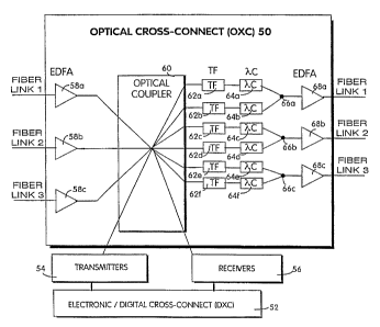
An optical cross-connect architecture for effecting pure wavelength switching
in accordance with one embodiment of the present invention is now be described
in
conjunction with FIGURE 4. In this optical cross-connect architecture,
wavelength
channel routing and switching is entirely performed in the wavelength domain
using
to tunable filters and wavelength converters. For purposes of explanation
only, three
optical fiber input links are connected to the optical cross-connect 50 with
each fiber
link carrying plural wave division multiplexed channels. Of course, more than
three
links could be accommodated. In this embodiment, in order to avoid channel
contentions within the optical cross-connect, the carrier wavelength "combs"
I5 multiplexed onto different optical fiber links must occupy adjacent, non-
overlapping
portions of the optical spectrum. The same configuration of three output
optical f ber
links are shown leaving the optical cross-connect 50. The optical signals on
each
fiber link may be amplified using suitable optical amplifiers 58a, 58b...58n,
such as
erbium-doped fiber amplifiers {EDFAs). Similarly, output EDFA amplifiers 68a,
68b...68n may be provided to amplify the output signals generated by the
optical
cross-connect. Although these amplifiers are not essential to the optical
cross-connect
architecture, they are desirable to boost the signal level because of the
combined
losses of the fiber path and the components in the optical cross-connect node.
2S The wavelength channels coming from the input fiber links 1, 2, and 3, as
well
as optical wavelength channels locally generated by electro-optical
transmitters 54
connected to digital cross-connect (DXC) 52, are combined by an optical
coupler 60,
such as a star coupler, that broadcasts the combined signal to each of the
coupler's
output ports. The star coupler outputs are grouped into 3 groups of N outputs,
( N
being the number of wavelength channels), one group for each output fiber.
This
means that the entire set of wavelength channels entering the node is made
available
on each output port of the optical coupler. As a result, any wavelength
channel may
be routed from any input fiber to any wavelength channel of any output fiber
link.
The outputs of the optical coupler 60 are connected to respective tunable f
lters 62.
Six tunable optical filters 62a-62f are shown to illustrate the nonlimiting,
simplest
example where each input and output fiber link includes two wavelength
channels.
As a result, there are a total of six (3 links x 2 channels) possible
wavelengths to be
CA 02237294 1998-OS-11
WO 97/18685 PCT/SE96/01465
II
selectively routed to any one of the output links. Of course, more than two
wavelength channels may be multiplexed on to a single fiber. Each output port
of the
optical coupler 60 then is connected to one of the tunable optical filters 62a-
62f which
is tuned to one of the six possible wavelength channels. Accordingly, the
tunable
s filter 62, by being tuned to a particular wavelength, selects or routes a
wavelength
channel having that particular wavelength from the optical coupler 60 to its
output
optical fiber link, i.e., wavelength channel routing.
Each tunable filter's output is connected to a corresponding wavelength
l0 converter 64a-64f which performs wavelength channel switching. In other
words, the
wavelength converter shifts, if desired, the input wavelength to a different
output
wavelength. As a result, the information contained on one wavelength channel
is
"switched" to another wavelength channel. Of course, the wavelength converter
need
not switch the wavelength if the channel is already at the desired wavelength.
Output
15 signals from each wavelength converter 64a-64f are combined at
corresponding
combiners 66a-66c to multiplex plural wavelength channels onto a single
optical fiber
link, i.e., wavelength division multiplexing. In this nonlimiting example,
since there
are two wavelength channels per link, each combiner multiplexes two frequency
converter outputs onto a single output link.
No optical space switch is required because the wavelength channels are
switched in the wavelength domain rather than in the space domain. The use of
wavelength converters as switching elements increases network flexibility,
simplifies
management of the network, and reduces the cost of the optical cross-connect.
Any suitable tunable filter could be used for elements 62a-62f such Fabry-
Perot and acousto-optic filters and active filters on Distributed Bragg
Reflector
(DBR). These devices have the advantages of optical gain, narrow filter
linewidth,
and potential for multifunctionality as well as monolithic integration with
other opto-
electronic devices.
An example wavelength converter based on four wave mixing (FWM) in
semiconductor traveling wave amplifiers (SOAs) is now described in accordance
with
FIGURES S and 6. Four wave mixing is a nonlinear effect that takes place when
two
waves at different wavelengths are injected into a semiconductor optical
amplifier.
Referring to FIGURE 5, a frequency converter based on FWM in an SOA is
obtained
by injecting at the SOA input an input signal 5 to be converted (centered at
frequency
CA 02237294 1998-OS-11
WO 97/18685 PCT/SE96/01465
12
f~) and an optical pump ~, (at frequency f2) with the same linear
polarization. Material
optical nonlinearities in the SOA produce a third output field o (which is the
conjugate of the input signal S centered at frequency f3~ shifted in frequency
by = f3 -
fi which is the detuning between pump and input signal. The field at frequency
o has
the same spectrum of S (but with a reverse frequency spectrum} so that the
signal
modulation is preserved, and the carrier wavelength of S is translated by a
conversion
interval = o - 5.
Different physical phenomena can cause four wave mixing in a semiconductor
io optical amplifier including carrier density pulsation induced by pump
signal "beating"
(i.e., referring to beat frequency) inside the active region or by nonlinear
gain and
index saturation due to intraband carrier dynamics. When the input signal is
injected
into a laser at frequency f, which is slightly detuned with respect to the
lacing or
pump frequency f2, a modulation is produced at the beat frequency of the
carrier
density, and consequently, of both the gain and refractive index. The
frequency
(through the refractive index) and the intensity (through the gain)
modulations of the
field generate two sidebands in the spectrum. One of them is the same
frequency as
the injected field, and the other is at a frequency of Zf2 - fi. When the
injected field is
modulated at low frequency with respect to the difference between f~ and fZ,
the
output of the new frequencies are also modulated. The modulation is the
conjugate f3
of the input signal fl if the gain nonlinearity is independent of frequency.
An example frequency conversion scheme is shown in FIGURE 6. Input
optical waves including the signal 5 and the pump p are coupled to a
semiconductor
optical amplifier 71. The pump signal is generated by a tunable pump laser 74
regulated by an appropriate control current. Thus, by changing the control
current and
therefor the pump, the wavelength translation amount is easily changed. The
input
signal and the pump have a frequency difference of and when combined, as
described above with respect to FIGURE 5, induce a modulation of the carrier
density
3o at that frequency difference. The modulation affects the entire gain
spectrum because
of the homogeneity of the gain saturation. The input signal can be translated
to any
other wavelength in the optical spectrum. The optical filter 72 is tuned to
suppress
the pump and original signal from the SOA output to leave only the wavelength
translated output signal.
The FWM SOA wavelength converter can be used to wavelength convert a
single wavelength channel or an entire comb/set of wavelength channels by an
CA 02237294 1998-OS-11
WO 97/18685 PCT/SE96/01465
13
amount . The FWM conversion process is independent of the signal or its
spectrum.
As a result, an intensity modulated. signal, a WDM comb of intensity modulated
signals, and even analog signals can be wavelength converted using this FWM
conversion process.
s
FIGURES 7A and 7B illustrate a management system architecture for
controlling a plurality of optical cross-connects. The management architecture
includes three processor layers including the operating system 100, mediation
devices
102, and device processors 104 connected over a separate "administration
network
l0 106". The operating system 100 allows an operator to reconfigure the
network, set up
protection paths, and supervise status. A man machine interface may be
provided at
the operating system I00 to graphically display the overall network
configuration or
the configuration of individual nodes. Configuration management automatically
establishes channels between the end terminals in the network by allocating
15 appropriate wavelength channels and setting up connections automatically
using a
routing algorithm that calculates and automatically selects free paths and
channels.
One mediation device is located at each cross-connect node and distributes
commands
for the operating system to the device processors. The principle task of the
mediation
device is to maintain the communication link; however, additional
functionality may
20 be allocated to the mediation devices, e.g., control of signal level
equalization across
the node.
One mediation device 102 is located at each cross-connect node and
distributes commands from the operating system 100 to the device processors
104. A
25 principle task of the mediation device 102 is to maintain this
communication link, but
the.mediation devices may also perform other functions such as control signal
equalization across a node. Communication between each mediation device and
device processors is accomplished over an RS-485 bus. Device processors I04 in
each optical cross-connect control and monitor all necessary 'parameters. For
30 example" in the case of optical amplifiers, input and output power, pump
power
currents, and temperature may aII be monitored. Consider the optical amplifier
shown
in FIGURE 7. The input power, output power, pump po~.ver current, and
temperature
- may all be monitored as indicated. The device processor 104 processes both
analog
and digital signals and connects to other device processors using an RS-232
bus.
Another embodiment of a modular optical cross-connect architecture will now
be described in accordance with FIGURE 8 where similar elements from FIGURE 4
CA 02237294 1998-OS-11
WO 97/18685 PCT/SE96/01465
I4
have similar reference numerals in FIGURE 8. One of the drawbacks of the
optical
cross-connect architecture shown in FIGURE 4 is that wavelength contentions
occur
in the star coupler 60 if the input fiber links carry the same wavelengths.
Therefore,
wavelength reuse is prevented in the network because all of the wavelength
channels
must be different to avoid such contention in the node. FIGURE 8 illustrates
wavelength/frequency reuse in the network in that each of the input links 1,
2, and 3
includes similar frequencies (corresponding to wavelengths) f~ and f1. Again,
for
purposes of illustration, only three fiber links and two wavelength channels
per link
are shown.
1 o Four wave mixing in semiconductor optical amplifiers performs two
significant functions in the OXC architecture shown in FIGURE 8: photonic
switching and wavelength contention avoidance. The photonic switching function
performed in the FIGURE 8 architecture was already described above in
conjunction
with the description of the OXC architecture of FIGURE 4. With respect to the
latter
function, the use of wavelength converters avoids wavelength contentions that
would
occur at a node when two channels at the same wavelength are routed to the
same
node output. By shifting the wavelength of one of the channels to a different
wavelength, such contention is avoided thereby achieving a more reliable and
flexible
optical network. In a situation where plural wavelength channels are
multiplexed
onto one link, FWM SOA wavelength converters are used to shift the entire WDM
comb on each fiber link before the channels mix in the optical coupler.
In accordance with this embodiment of the present invention, input
wavelength converters 70a, 70b, and 70c shift the input frequencies of each
optical
wavelength channel to a different set of frequencies. As with the example used
with
respect to FIGURE 4, the example in FIGURE 8 assumes only three fiber Links
with
each link carrying only two wavelength channels. However and in contrast to
FIGURE 4, the two wavelength channels on each input fiber link in FIGURE 8 are
the
same--f0 and fl . Of course, a much Larger number of links and wavelength
channels
could be used. Thus, the comb of input frequencies f0 and fl on each fiber
link may
be shifted by its wavelength converter 70 to another comb or set of
frequencies. In
the example, the input wavelength frequencies fb and f1 on optical link I are
not
translated by wavelength converter 70a (although they could be if desired).
The
wavelength channels ft? and fl on optical link 2 are converted in wavelength
converter
70b to frequencies f3 and f4 respectively. The wavelength channels fl7 and fI
on
optical Link 3 are converted in wavelength converter 70c to corresponding
frequencies
f~ and f6 which. are different from frequencies f3 and f4. As a result,
individual
CA 02237294 1998-OS-11
WO 97/18685 - PCT/SE96/01465
wavelength channels coupled in optical coupler 60 do not collide/contend. To
accomplish wavelength translation of such simplified WDM combs, FWM SOA
wavelength converters are used at the inputs to the optical coupler 60.
5 The pairs of tuning filters 62a-62f and wavelength converters 64a-64f
already
described above with respect to FIGURE 4 perform routing of different channels
to
the output fibers and wavelength switching in the wavelength domain,
respectively.
The wavelength converters 64a-64f may, if desired, translate the f3 and f4
channels as
well as f5 and f6 channels back to the corresponding fb and fi
10 frequencies(wavelengths) which were received by wavelengths converters 70.
This
feature permits the node wavelength switching function to remain transparent
outside
the node. Similarly, the outputs from pairs of wavelength converters are
combined in
respective combiners to reconstitute the WDM channels on each link.
I5 The optical cross-connect architectures disclosed in FIGURES 4 and 8 are
non-blocking, prevent wavelength channel contention, and are both Link and
wavelength modular. As a result, additional input and output fiber links can
be
simply inserted with each new fiber having, for the architecture in FIGURE 4,
an
additional corresponding tunable filter 62 and wavelength converter 64 pair.
For the
2o architecture in FIGURE 8, another wavelength converter 70 is also added.
Such link
and corresponding link component additions do not affect or change the pre-
existing
optical cross-connect node components or the node's basic structure, and as a
result,
the optical cross-connect is link modular.
2s Similarly, new wavelength channels may be individually and modularly added
to the existing comb of wavelength channels on each input fiber. An added
wavelength channel simply requires the addition of a tunable filter/
wavelength
converter pair. The total number of added filter/converter pairs equals the
total
number of added wavelengths without any change to the pre=existing devices.
3o Accordingly, the optical cross-connect is wavelength modular.
In instances where the optical coupler 60 is overdimensioned and has
additional input and output ports, new links and wavelengths can be added
without
any change to the pre-existing OXC. Even if a higher capacity optical coupler
is
3s required to add new links and/or wavelengths, that higher capacity optical
coupler is
substituted for the existing coupler. The only hardware changes would be to
disconnect and reconnect to the input and output coupler ports. The optical
coupler is
CA 02237294 1998-OS-11
WO 97/18685 PC'r/SE96/01465
16
by far the least expensive component in the OXC and is certainly much more
economically replaced than an optical space switch. As a result, the optical
cross-
connect can be upgraded without traffic disruption and with minimum
incremental
costs as the market demands.
Using the OXC architecture of the present invention, the optical cross-connect
nodes are not network bottle-necks. In addition, in future networks such as
broadband-ISDN (B-ISDN) whose initial traffic demands will likely be low,
communication networks can be flexibly and economically upgraded with an
optical
1o path layer while also supporting future growth and incremental investment
as traffic
demands increase. The optical cross-connect architectures of the present
invention
offer high link and wavelength modularity. Additional links may be added to
the
OXC simply by adding a number of components or modules that match the number
of
additional links. Similarly, when adding plural wavelengths, the number of
I5 components corresponds directly to the number of additional wavelengths.
The
upgrading expense is confined to the cost the new link and the associated
components
and possibly a new optical coupler. The node architecture need not be
redesigned, nor
do expensive space switches need to be purchased. As already described,
another
advantage of these architectures is that they minimize the number of total
20 wavelengths used in the network because they employ a virtual path
wavelength
technique that relies on wavelength switching rather than allocating one
wavelength
for every channel in the network.
Both architectures directly support the possible routing of a given wavelength
25 channel to more than one output fiber, i.e., multicasting. Moreover, any
multicasted
signal can travel on any wavelength independent of originating wavelength and
of the
other multicasted signals. This is particularly attractive for applications
that require
transport of signals from a production center to several access nodes in
different
geographic locations, e.g., broadcasting television signals. Because FWM SOA
30 wavelength converters can translate analog signals as well as digital
signals, the
present invention finds particular application to multicasting of television
signals over
transport networks.
While the invention has been described in connection with what is presently
35 considered to be the most practical and preferred embodiment, it is to be
understood
that the invention is not to be limited to the disclosed embodiment, but on
the
CA 02237294 1998-OS-11
WO 97/18685 PCT/SE96/01465
17
contrary, is intended to cover various modifications and equivalent
arrangements
included within the spirit and scope of the appended claims.