Language selection

Search

Patent 2237360 Summary

Third-party information liability

Some of the information on this Web page has been provided by external sources. The Government of Canada is not responsible for the accuracy, reliability or currency of the information supplied by external sources. Users wishing to rely upon this information should consult directly with the source of the information. Content provided by external sources is not subject to official languages, privacy and accessibility requirements.

Claims and Abstract availability

Any discrepancies in the text and image of the Claims and Abstract are due to differing posting times. Text of the Claims and Abstract are posted:

  • At the time the application is open to public inspection;
  • At the time of issue of the patent (grant).
(12) Patent: (11) CA 2237360
(54) English Title: DISPENSING CAP FOR A LIQUID CONTAINER
(54) French Title: CAPUCHON DISTRIBUTEUR POUR UN RECIPIENT CONTENANT UN LIQUIDE
Status: Deemed expired
Bibliographic Data
(51) International Patent Classification (IPC):
  • B05C 17/00 (2006.01)
  • A45D 34/04 (2006.01)
  • B43K 5/18 (2006.01)
  • B43L 19/00 (2006.01)
  • B65D 51/32 (2006.01)
  • B65D 83/00 (2006.01)
(72) Inventors :
  • KELDERS, JOHANNES HUBERTUS JOZEF MARIA (Netherlands (Kingdom of the))
  • BROUWER, MARKUS FRANCISKUS (Netherlands (Kingdom of the))
(73) Owners :
  • HENKEL KOMMANDITGESELLSCHAFT AUF AKTIEN (Germany)
(71) Applicants :
  • HENKEL RAYCAP PRODUKTIE B.V. (Netherlands (Kingdom of the))
(74) Agent: FETHERSTONHAUGH & CO.
(74) Associate agent:
(45) Issued: 2005-07-05
(86) PCT Filing Date: 1996-11-11
(87) Open to Public Inspection: 1997-05-15
Examination requested: 2001-10-24
Availability of licence: N/A
(25) Language of filing: English

Patent Cooperation Treaty (PCT): Yes
(86) PCT Filing Number: PCT/NL1996/000443
(87) International Publication Number: WO1997/017213
(85) National Entry: 1998-05-11

(30) Application Priority Data:
Application No. Country/Territory Date
1001626 Netherlands (Kingdom of the) 1995-11-10

Abstracts

English Abstract


The invention relates to a dispensing cap (1) for a liquid container (5)
provided with an applicator means (6) fixed thereto and for insertion into an
opening of the liquid container, wherein the dispensing cap (1) has a closable
outlet opening (8) in its outer end located opposite the applicator means (6),
which opening is connected along a channel (10) running through the dispensing
cap to a feed aperture arranged in the vicinity of the applicator means, and a
closing member (12) co-acting with the feed aperture. The invention likewise
relates to a liquid container provided with a dispensing cap of the above
described type.


French Abstract

L'invention concerne un capuchon distributeur (1) pour un récipient (5) contenant un liquide et auquel est fixé un applicateur (6). Ce capuchon (1) vient s'insérer dans une ouverture du récipient et il comprend un orifice (8) pouvant se fermer, situé à l'extrémité externe et opposée à celle de l'applicateur (6). Cette ouverture est reliée par un canal (10), traversant le capuchon, à une ouverture d'alimentation se trouvant au voisinage de l'applicateur et un élément de fermeture (12) coopère avec l'ouverture d'alimentation. L'invention concerne également un récipient à liquide pourvu du capuchon distributeur décrit.

Claims

Note: Claims are shown in the official language in which they were submitted.


4

CLAIMS:

1. Dispensing cap (1) for a liquid container (5)
provided with an applicator means (6) fixed thereto and for
insertion into an opening (4) of the liquid container (5),
wherein the dispensing cap (1) has a closable outlet opening
(8) in its outer end located opposite the applicator means
(6), which opening is connected along a channel (10) running
through the dispensing cap to at least one feed aperture
(11) arranged in the vicinity of the applicator means (6),
characterized by a closing member (12) co-acting with the
feed aperture (11).
2. Dispensing cap (1) as claimed in claim 1,
characterized in that the closing member (12) is movable in
the channel (10) between a first position closing the feed
aperture (11) and a second position leaving clear the feed
aperture (11).
3. Dispensing cap (1) as claimed in claim 2,
characterized in that the channel (10) has a first portion
(17) in which the feed aperture (11) is situated and the
dimensions of which correspond substantially with those of
the closing member (12), in addition to a widened portion
(15), the dimensions of which are larger than those of the
closing member (12).
4. Dispensing cap (1) as claimed in claim 3,
characterized in that the closing member (12) is ball-shaped
and the first portion (17) of the channel (10) takes the
form of a spherical segment.
5. Dispensing cap (1) as claimed in claim 3 or 4,
characterized by guide members (16) protruding from side
walls of the widened portion (15) of the channel (10).


5

6. Dispensing cap (1) as claimed in claims 3-5,
characterized by spacer members (19) protruding from an end
wall of the channel (10).
7. Dispensing cap (1) as claimed in any one of claims
1 to 6, characterized by an annular sealing member (14)
arranged round the applicator means (6) and for inserting
close-fittingly into the opening (4) of the liquid container
(5).
8. Dispensing cap (1) as claimed in claim 7,
characterized by a wiping member (14) arranged between the
opening (4) and the sealing member (20).
9. Dispensing cap (1) as claimed in claim 8,
characterized in that the wiping member (14) has a
cylindrical wall part (21) co-acting with the sealing member
(20).
10. Liquid container (5) provided with a dispensing
cap (1) as claimed in any one of claims 1 to 9.

Description

Note: Descriptions are shown in the official language in which they were submitted.


CA 02237360 1998-OS-11
WO 97/17213 PCT/NL96/00443
a Dispeasiag cap for a liquid coataiaer
The invention relates to a dispensing cap for a


liquid container provided with an applicator means fixed


thereto and for insertion into an opening of the liquid


container, wherein the dispensing cap has a closable


outlet opening in its outer end located opposite the


applicator means, which opening is connected along a


channel running through the dispensing cap to at least


one feed aperture arranged in the vicinity of the


applicator means.


Such a dispensing cap is known from EP-A-0 398


936. The known cap is intended for a bottle with


correction fluid and is provided with a brush for placing


in the neck of the bottle with which the correction fluid


can be applied and spread when larger areas have to be


corrected, and a pin tip with which smaller quantities
of


correction fluid can be dispensed.


The known dispensing cap has the drawback that,


after the use of the pin tip, correction fluid can remain


behind in the channel which, when the brush is


subsequently used, can then run out along the handle


thereof whereby an unintentionally large amount of


correction fluid is spread onto the error for correcting.


There is therefore the danger of for instance a part of
a


text round an error also being smeared with correction


fluid. In addition, an excess dose of correction fluid


results in a comparatively long drying time, while in


this manner the content of the bottle is also consumed


too quickly.


~ The invention therefore has for its object to


provide an improved dispensing cap of the above described


. type wherein these drawbacks do not occur. This is


achieved according to the invention by a closing member


co-acting with the feed aperture. Due to such a closing


member unused liquid is retained in the channel between


CA 02237360 1998-OS-11
WO 97/17213 PCT/NL96/00443
2
the feed aperture and the outlet opening and can
therefore not leak out.
Preferred embodiments of the cap according to
the invention are described in the dependent claims_
The invention also relates to a liquid
container provided with a dispensing cap as described
above.
The invention is elucidated with reference to
the annexed drawing, in which:
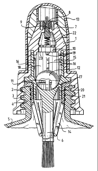
fig. 1 shows a longitudinal section of a
dispensing cap according to the invention arranged on a
liquid container in its rest position,
fig. 2 shows a section corresponding with fig.
1 of the liquid container with dispensing cap during use,
and
fig. 3 is a section corresponding with fig. 1
and 2 of the dispensing cap per se.
A dispensing cap 1 (fig. 1) is provided with an
internal screw thread 2 with which it can be screwed onto
a neck 4 of a container 5 likewise provided with screw
thread 3. An applicator means 6, in the example shown a
brush, is fixed in the dispensing cap 1. With brush 6 a
liquid arranged in container 5, for instance correction
fluid, can be applied in dosed manner to a surface such
as a sheet of paper which has been written on. A
comparatively large amount of liquid is herein dispensed.
In order to also enable dispensing of more
finely spread liquid the dispensing cap 1 is provided on
its outer end 7 located opposite brush 6 with an outlet
opening 8 which is closable by means of a needle valve 9.
This needle valve 9 is movable in the outlet opening 8
and is biased by a pressure spring 22 connected to cap 1
to a rest position closing the opening 8. Valve 9 is
pressed inward counter to the biasing force of spring 22
and thus leaves the opening 8 clear when it is pressed
onto a surface (fig. 2). The outlet opening 8 is
connected via a channel 10 running through dispensing cap
1 to a plurality of radially directed feed apertures 11


CA 02237360 1998-OS-11
WO 97/17213 PCT/NL96/00443
3
which are arranged round the upper part of the brush 6
and which communicate with the interior of liquid
container 5.
In order to prevent liquid which may have


collected in channel 10 from leaking out through


apertures 11 during the use of brush 6, the dispensing


cap 1 according to the invention is provided with a


closing member, in the example shown a ball 12. The ball


12 is movable in a widened portion 15 of channel 10


between a plurality of guide ribs 16 arranged distributed


along the walls of the widened channel portion 15. Formed


between these guide ribs 16 are bypass channels 18


whereby the liquid can pass along the closing ball 12


when dispensing cap 1 is pressed with its outlet opening


8 onto a surface. The end portion 17 of channel 10


directed toward brush 6 in which the feed apertures 11


debouch herein takes a spherical segment-shaped form such


that the ball 12 can be received sealingly therein. On


the top side the channel 10 is provided with a plurality


of spacer members 19 whereby the ball 12 is held clear
of


the edge 23 of the narrowed upper portion of channel 10,


thus ensuring an uninterrupted liquid flow from container


5 through the outlet opening 8 of cap 1.


In addition to the needle valve 9 a closing cap


13 is also arranged over outlet opening 8 so as to


prevent drying and/or leakage. An annular sealing member


or apron 20 is further arranged round brush 6. This


sealing member 20 is received close-fittingly in a


cylindrical part 21 of a wiping member 14 which is in


turn received close-fittingly in the neck 4 of container


5. Leakage round the brush 6 is thus prevented when


dispensing cap 1 a.s pressed with the outlet opening 8


onto a surface while possibly not being screwed


completely into place on container 5.


Representative Drawing
A single figure which represents the drawing illustrating the invention.
Administrative Status

For a clearer understanding of the status of the application/patent presented on this page, the site Disclaimer , as well as the definitions for Patent , Administrative Status , Maintenance Fee  and Payment History  should be consulted.

Administrative Status

Title Date
Forecasted Issue Date 2005-07-05
(86) PCT Filing Date 1996-11-11
(87) PCT Publication Date 1997-05-15
(85) National Entry 1998-05-11
Examination Requested 2001-10-24
(45) Issued 2005-07-05
Deemed Expired 2008-11-12

Abandonment History

There is no abandonment history.

Payment History

Fee Type Anniversary Year Due Date Amount Paid Paid Date
Application Fee $300.00 1998-05-11
Maintenance Fee - Application - New Act 2 1998-11-12 $100.00 1998-11-12
Registration of a document - section 124 $100.00 1999-04-28
Registration of a document - section 124 $100.00 1999-10-04
Maintenance Fee - Application - New Act 3 1999-11-11 $100.00 1999-10-28
Maintenance Fee - Application - New Act 4 2000-11-13 $100.00 2000-10-02
Maintenance Fee - Application - New Act 5 2001-11-12 $150.00 2001-10-02
Request for Examination $400.00 2001-10-24
Maintenance Fee - Application - New Act 6 2002-11-11 $150.00 2002-10-07
Maintenance Fee - Application - New Act 7 2003-11-11 $150.00 2003-10-14
Maintenance Fee - Application - New Act 8 2004-11-11 $200.00 2004-10-08
Final Fee $300.00 2005-04-20
Maintenance Fee - Patent - New Act 9 2005-11-11 $200.00 2005-10-06
Maintenance Fee - Patent - New Act 10 2006-11-13 $250.00 2006-10-06
Owners on Record

Note: Records showing the ownership history in alphabetical order.

Current Owners on Record
HENKEL KOMMANDITGESELLSCHAFT AUF AKTIEN
Past Owners on Record
BROUWER, MARKUS FRANCISKUS
HENKEL RAYCAP PRODUKTIE B.V.
KELDERS, JOHANNES HUBERTUS JOZEF MARIA
Past Owners that do not appear in the "Owners on Record" listing will appear in other documentation within the application.
Documents

To view selected files, please enter reCAPTCHA code :


To view images, click a link in the Document Description column. To download the documents, select one or more checkboxes in the first column and then click the "Download Selected in PDF format (Zip Archive)" or the "Download Selected as Single PDF" button.

List of published and non-published patent-specific documents on the CPD .

If you have any difficulty accessing content, you can call the Client Service Centre at 1-866-997-1936 or send them an e-mail at CIPO Client Service Centre.


Document
Description 
Date
(yyyy-mm-dd) 
Number of pages   Size of Image (KB) 
Cover Page 1998-08-17 1 53
Representative Drawing 1998-08-17 1 14
Abstract 1998-05-11 1 55
Description 1998-05-11 3 137
Claims 2005-02-16 2 67
Claims 1998-05-11 2 59
Drawings 1998-05-11 3 103
Claims 2004-11-15 2 62
Representative Drawing 2005-06-10 1 18
Cover Page 2005-06-10 1 51
Fees 1999-10-28 1 38
Assignment 1998-05-11 2 94
PCT 1998-05-11 8 290
Correspondence 1998-08-04 1 29
Assignment 1999-04-28 2 96
Assignment 1999-06-04 1 48
Assignment 1999-10-04 2 100
Prosecution-Amendment 2001-10-24 1 47
Prosecution-Amendment 2002-03-20 1 34
Prosecution-Amendment 2005-02-16 2 63
Fees 1998-11-12 1 44
Prosecution-Amendment 2004-05-20 2 33
Prosecution-Amendment 2004-11-15 3 95
Prosecution-Amendment 2005-02-09 1 32
Correspondence 2005-04-20 1 30