Note: Descriptions are shown in the official language in which they were submitted.
CA 02237371 2005-10-21
1 28361/DA.D
DEFLECTABLE TIP ELECTRODE CATHETER
FIELD OF THE INVENTION
This invention relates to electrode catheters having a steerable or
deflectable tip and
more particularly to a deflectable tip electrode. catheter having an elongated
single lumen
catheter body containing a compression coil which is resistant to compressive
forces.
BACKGROUND OF THE INVENTION
Steerable or deflectable tip cardiovascular catheters are useful in many
applications,
being a marked improvement over catheters with fixed tip curves. They are
especially useful in
the field of electrophysiology for performing radio frequency ablation of
abnormal electrical
pathways in the heart.
There are presently several useful designs of steerable tip catheters. One
such
steerable tip catheter is described in U.S. Reissue Patent No. 34,502. The
catheter
described has an elongated catheter body and tip portion which can be
deflected into a
semi-circle in one direction. In addition, the catheter body and tip portion
can be rotated.
By tip deflection, catheter rotation and catheter translation, i.e.,
lengthwise movement of
the catheter, contact of the tip portion with most areas of a heart chamber
may be made.
In the catheter described in Reissue Patent No. 34,502, the deflectable tip
section
has two opposing offset lumens, one for electrode lead wires and one for a
pulley wire. The
pulley wire is disposed within a tiny Teflon~ tube or sheath that extends the
entire length
of the catheter tip and body. In the catheter body, the pulley wire within the
Teflon sheath
and the lead wires extend centrally within a nylon stiffener tube. The lumen
of the nylon
' tube is just big enough to pass the pullet wire with its Teflon sheath and
the lead wires,
thereby maintaining the pulley wire in an substantially axial or central
position. This
central pulley wire, when pulled by the control handle at the proximal end of
the body,
deflects the tip and also compresses the catheter body including the nylon
stiffener.
Because the pulley wire is almost exactly on the axis of the catheter body,
there is almost
no bending moment and hence almost no bending of the catheter body. Even so,
compression of the catheter body 'does cause a certain waviness of the body,
which results
in a slight loss of performance.
CA 02237371 1998-OS-12
1 The open lumen catheter described in U.S. Patent No. 5,431,168 has a
compression
coil deployed in one of three off axis lumens in a braided catheter body. In
this catheter,
the compressive forces on the catheter body when the pulley wire is
manipulated to deflect
the tip is transferred to the compression coil. This is done by gluing the
distal and proximal
ends of the compression coil to the ends of the catheter body using a
sufficient amount of
an appropriate glue to effect shear joints that are stronger than the forces
created by the
pulley wire. This design requires a dedicated compression coil lumen. Because
the pulley
wire and compression coil are not located on the axis of the catheter body,
manipulation of
the catheter is compromised somewhat in order to achieve an open lumen for
irrigation.
SUbIMARY OF THE INVENTION
The present invention provides a single lumen deflectable tip electrode
catheter
having a substantially non-compressive catheter body. The catheter comprises
an
elongated catheter body, a control handle at the proximal end of the catheter
body and a
deflectable tip section at the distal end of the catheter body which carries
one or more
electrodes. The catheter body comprises a central, i.e., axial, lumen. The tip
section
comprises at least one, and preferably at least two off axis lumens which are
in
communication with the central lumen of the catheter body.
A pulley wire extends through the central lumen of the catheter body and into
one
off axis lumen of the catheter tip section, the distal end of the pulley wire
being anchored
to the side wall of the tip section, preferably near the distal end of the tip
section. The
pulley wire preferably comprises a lubricious Teflon sheath to increase
slidability of the
pulley wire within the catheter body and tip section.
In the central lumen of the catheter body, there is provided a compression
coil in
surrounding relation to the pulley wire. The compression coil is flexible,
i.e., bendable, but
is substantially non-compressible. The diameter of the compression coil is
sufficiently less
than the diameter of the central lumen of the catheter body to provide a space
or gap
' through which electrode wires may pass. The proximal end of the compression
coil is
fixedly attached to the proximal end of the catheter body by a first glue
joint. The distal
end of the compression coil is fixedly attached to the distal end of the
catheter body or
proximal end of the tip section by a second glue joint. First and second
tunnels preferably
made from short pieces of non-conductive tubing, e.g., polyamide tubing,
extend through
the first and second glue joints. The tunnels are sufficiently large to allow
the passage of
electrode lead wires therethrough. In a preferred embodiment, the outer
surface of the
-2-
CA 02237371 1998-OS-12
1 compression coil between the glue joints is covered-by a non-conductive
sleeve, preferably
polyamide tubing. Preferably the sleeve overlaps the tunnels.
BRIEF DESCRIPTION OF THE DRAWINGS
FIG. 1 is a side view of a preferred electrode catheter constructed in
accordance with
the present invention.
FIG. 2 is a fragmentary longitudinal, cross-sectional side view of the
catheter of FIG.
1 showing the distal end of the catheter body and proximal end of the tip
section in cross-
section except for the compression coil and tunnel.
FIG. 3 is a transverse cross-sectional view of the catheter body shown in FIG.
2
taken along line 3-3.
FIG. 4 is a cross-sectional view of a portion of the catheter tip section
showing a
preferred means for anchoring the puller wire.
FIGS. 5a and 5b are top and side cross-sectional views of a preferred puller
wire
anchor.
FIG. 6 is a cross-sectional view of a portion of the catheter tip section
showing
another preferred means for anchoring the pulley wire.
FIG. 7 is a cross-sectional view of the distal portion of a catheter tip
section
comprising a tip electrode showing yet another preferred means for anchoring
the pulley
wire.
DETAILED DESCRIPTION
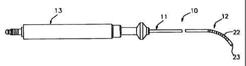
A particularly preferred electrode catheter constructed in accordance with the
present invention is shown in Figs. 1- 5. The electrode catheter 10 comprises
in elongated
catheter body 11 having proximal and distal ends, a catheter tip section 12 at
the distal
end of the catheter body 11 and a control handle 13 at the proximal end of the
catheter body
11.
' The catheter body 11 comprises an elongated tubular construction having a
single,
central or axial, lumen 15. The catheter body 11 is flexible i.e. bendable,
but substantially
non-compressible along its length. The catheter body 11 may be of any suitable
construction and made of any suitable material. A presently preferred
construction
comprises an outer polyurethane wall 17 containing a braided stainless steel
mesh. Lining
the interior of the polyurethane wall 17 is a nylon stiffening tube 18, the
interior of which
forms the central lumen 15. The nylon stiffening tube 18 is fixedly attached
to the outer
polyurethane wall 17, typically at its proximal end by polyurethane glue or
the like.
-3-
CA 02237371 1998-OS-12
1 The length and diameter of the catheter body 11 are not critical and may
vary
according to the application. For the electrode catheter 10 shown in the
accompanying
drawings, a length of about 48 inches, an outer diameter of about 0.09 inch in
an inner
lumen diameter of about 0.035 inch is presently preferred.
The catheter tip section 12 comprises a short section of flexible tubing 16
having a
pair of non-overlapping, side-by-side off axis lumens 19 and 21. The catheter
tip section 12
may be made of any suitable material and is preferably more flexible than the
catheter
body. A preferred material for the catheter tip is polyurethane having a
hardness of Shore
D55. The catheter tip section 12 preferably comprises a braided stainless
steel mesh
similar to that of the catheter body 11.
The diameter of the catheter tip section 12 is not critical, but is preferably
about the
same as, or slightly smaller, than diameter of the catheter body 11. The
length of the
catheter tip section 12 is likewise not critical. In the embodiment shown, the
length of the
catheter tip section 12 is about 3 inches and the diameter is about 0.09 inch.
The catheter tip section 12 carries a plurality of a electrodes 22. The
electrodes 22
are in the form metal rings, the outer diameter of the electrodes 22 being
about the same
as the outer diameter of the flexible tubing 16 of the tip section so that the
electrodes 22
form a smooth, continuous surface with that outer of the surface of the
flexible tubing 16.
Alternatively, the electrodes 22 may have an outer diameter slightly larger
than the
diameter of the flexible tubing 16 so that the electrodes 22 protrude slightly
from the
surface of the flexible tubing 16. A rounded end electrode 23 is positioned at
the distal end
of the catheter tip section 12. The longitudinal length and spacing of the
ring electrodes are
not critical. A longitudinal length of about lmm and a spacing from about 2mm
to about
5mm are presently preferred.
A preferred means for attaching the catheter tip section 12 to the catheter
body 11
is shown in Fig. 2. The proximal end of the catheter tip section 12 comprises
an outer
circumferential notch 27 which receives the inner surface of the outer wall 17
of the
' catheter body. In the arrangement shown, a Teflon~ spacer 20 having about
the same
inner and outer diameters as the nylon stiffening tube 18 lies between the
distal end of the
nylon stiffening tube 18 and the proximal end of the catheter tip section 12..
A puller wire 30, preferably made of stainless steel, Nitinol, Kevlor, carbon
fiber or
the like, extends from the control handle 13 through the central lumen 15 of
the catheter
body and into the first lumen 19 of the catheter tip section 12. The pulley
wire 30 extends
into the first lumen 19 of the catheter tip section 12 to a position near the
distal end of the
catheter tip section 12 and is fixedly attached to the wall of the flexible
tubing 16. The
-4-
CA 02237371 1998-OS-12
1 pulley wire 30 is preferably coated with a Teflon coating or the like for
lubricity. Within the
Teflon~ spacer and the catheter tip section 12, the pulley wire 30 lies within
a Teflon~
sheath 31.
Within the catheter body 11, the pulley wire 30 extends through a compression
coil
32. The compression coil is made of a suitable metal, e.g., stainless steel,
which is tightly
wound on itself to provide flexibility, i.e., bending, but to resist
compression. The
compression coil 32 preferably has a length a little longer than the length of
the nylon
stiffening tube 18 and extends into the Teflon~ spacer 20. The inner diameter
of the
compression coil 32 is slightly larger than the outer diameter of the pulley
wire 30. This
allows the pulley wire 30 to slide easily through the compression coil 32. The
inner
diameter of the central lumen 15 and the outer diameter of the compression
coil 32 are
selected to provide a small gap or space 33 between the compression coil 32
and the inner
surface of the nylon stiffening tube 18 which forms the central lumen 15 for
passage of
electrode lead wires 34.
The outer surface of the compression coil 32 is covered by a flexible, non-
conductive
sheath 36 to prevent contact between the electrode lead wires 34 in the gap 33
and the
compression coil 32. A non-conductive sheath 36 made of polyamide tubing is
presently
preferred.
The compression coil 32 is fixedly attached to the proximal and distal ends of
the
nylon stiffening tube 18 by glue joints 38 preferably made from polyurethane
glue or the
like. At each glue joint 38, the non-conductive sheath 36 surrounding the
compression coil
32 is removed so that the glue contacts the compression coil 32 directly. The
glue may be
applied through a syringe or the like to the outer circumference of the end of
the
compression coil. Glue applied to such a location seeps inwardly between the
compression
coil and the wall forming the lumen. Upon drying, the glue joint is formed.
Alternatively,
the glue may be applied by means of a syringe or the like through a hole
between the outer
surface of the catheter body and the lumen. Such a hole may be formed for
example by a
needle or the like which punctures the catheter body wall and is heated
sufficiently to form
a permanent,hole. The glue is introduced through the hole to the outer surface
of the
compression coil and wicks around the outer circumference to form a glue joint
about the
entire circumference of the compression coil.
If the latter method is used, it is understood that the distal end of the
compression
coil could be located in the proximal portion of the catheter tip section
rather from at the
distal end of the catheter body. Such an embodiment provides added support to
the
juncture of the catheter body and catheter tip section.
-5-
CA 02237371 1998-OS-12
1 A tunnel is formed through each glue joint 38 by means of a small piece of
non-conductive tubing 41 preferably made of polyamide, positioned adjacent the
compression coil 32 within the central lumen 15. The length of the tubing 41
is sufficient
to extend entirely through the glue joint 38 and to overlap the non-conductive
sheath 36
around the compression coil 32. The tubing 41 may be generally circular in
cross section
or may be deformed to have, for example, a generally C-shaped cross-sectional
shape. The
interior cross-sectional area of the tubing 41 is sufficient to allow
electrode lead wires 34
to pass therethrough. The Tubing 41 which forms a tunnel through the distal
glue joint 38
preferably extends a short distance into the Teflon~ spacer 20.
In an exemplary embodiment wherein the outer diameter of the catheter body 11
is
0.09 inch, the outer diameter of the puller wire 30 is about 0.00 r inch to
about 0.010 inch,
the thickness of the Teflon coating 31 around the puller wire 30 is about
0.0001 to about
0.0002 inch, the inner and outer diameter of the compression coil 32 is 0.009
inch and 0.018
inch respectively, the thickness of the sheath 36 surrounding the compression
coil 32 is
about 0.001 inch, the inner diameter of the central lumen 15 is about 0.035,
and the inner
diameter of the tunnels is from about 0.015 to about 0.020 inch. It is
understood that all
of these dimensions may vary as desired.
A preferred means for attaching the puller wire 30 to the tubing 16 of the
catheter
tip section 12 is shown in Figs. 4 and 5. A T-shaped anchor 42 is formed which
comprises
a short piece of tubular stainless steel 43, e.g. hypodermic stock, which is
fitted over the
distal end of the puller wire 30 and crimped to fixedly secure it to the
puller wire 30. The
distal end of the tubular stainless steel 43 is fixedly attached e.g. by
welding, to a stainless
steel cross-piece 44 such as stainless steel ribbon or the like. The cross-
piece 44 sits in a
notch 46 in a wall of the flexible tubing 16 which extends into the lumen 19.
This provides
a small opening through the wall of the flexible tubing 16 into the lumen 19.
The stainless
steel cross-piece 44 is larger than the opening and, therefore, cannot be
pulled through the
opening. The portion of the notch 46 not filled by the cross-piece 44 is
filled with glue 47
or the like, preferably a polyurethane glue, which is harder than the material
of the flexible
tubing 16. Rough edges, if any, of the cross-piece 44 are polished to provide
a smooth,
continuous surface with the outer surface of the flexible tubing 16.
With reference to Fig. 6, there is shown an alternate embodiment wherein the
puller
wire 30 extends to the distal end of the lumen 19 with the cross-piece 44 of
anchor 42 lying
beyond the end of lumen 19. The cross-piece 44 is fixed at this position by a
polyurethane
cap 48 which also seals the distal end of the catheter tip section 12. Because
the cross-piece
44 is larger than the diameter of the lumen 19, the anchor 42 cannot be pulled
back into the
-6-
CA 02237371 2005-12-29
Z lumen 19 when the tip section 12 is deflected. This alh~ernative anchoring
arrangement is
useful when there is no tip electrode. If a tip electrode is present, the
pullet wire 30 stay
be $xedly attached to the tip electrode or anchored through the side wall of
the t1p section
12 as shown in Fig. 4.
With reference to FrG. ?, there is shown yet another embodiment wherein the
tip
section 1'2 carries a tip electrode 28. The distal end of the puher wire 3U
extends into a hole
in the tip electrode 23 is attached thereto, e.g., by soldering. The hole in
the tip electrode
23 may be axial as shown or off axis as desired.
., The electrode Lead wire 3d likewise extends into a hold in the tip
electrode 23 and
is electrically bonded, e.g.. by soldering. thereto. It is to he understood
that any suitable
means ihr ~xedlY stlaching the pullet wire 3~ and electrode lead wire 34 to
the tip electrode
23 may be used as desired.
>~lectrnde lead wires S4 extend fiom the cotthrol handle 13 through the first
tunnel,
i.e., tubing 41, at the proximal end of the catheter body 11, through the
space 33 between
the coiapressina au~192 sad the inner surface of the ay1on stiffening tube 18
forming central
lumen 15, thxough the second tunnel, i.e., tubing dl, at the distal end of the
catheter body
11. and into lu~n 19 iu the Catheter tip section 12. The lead wires 34 are
attached to tht
electrodes 22 by axay conventional technique. In a pn5erred embodiment, you of
a
lead wire 34 to an electrode 22 is accomplished by first ma>cing a small hole
through the .
ED _v~all of the catheter tip section and into the second Iumea 21. Such a
hole may be created,
far example, by inserting a needle through. the tip section wall and heating
the neecL~e~~
sufficiently to form a permanent hole. A lead wire 34 is they drawn through
the hale by .:::,..:
using a micro hook or the like. The end of the lead wire 34 is then stripped
of any coat>,it~ '~"- . .
and soldered or welded to the underside of the electrode 22 which is then slid
into position .
over the hole and fixed is place with polyurethane glue or the like: .
Loagitutdinal movement of the pullet wire 30 relative~to the catheter body li
which
results i:n deRection of the catheter tip section 12 is accomplished by
maaipulatian of a
'suitable control handle 19. A particularly preferred control handle useful in
the present
invention is disclosed in I3:S. Patent Re134,502: ~ . ' . '.
The preceding description has been presented with reference to presently
preferred
embodiments of the invention Workers dolled in the art and technology to which
this
ixlvention pertains will. appreciate that alterations and changes in the
described structure
may be practuced without meaningfully departing from the principal, spirit and
scope of this
' invention.
-7-
I_'~J29/12/2D05 (15:12 I~953-246 i~received
CA 02237371 1998-OS-12
1 Accordingly, the foregoing description should not be read as pertaining only
to the
precise structures described and illustrated in the accompanying drawings, but
rather
should be read consistent with and as support to the following claims which
are to have
their fullest and fair scope.
10
20
30
_g_