Note: Descriptions are shown in the official language in which they were submitted.
CA 02237397 1998-OS-12
1
Our Reference: EIS-145-B PATENT
WATTHOUR METER SOCKET ADAPTER WITH
SNAP-ON JAW CONTACTS
BACKGROUND OF THE INVENTION
Field Of The Invention:
The present invention relates, in general, to
watthour meters and meter sockets and, more specifically,
to watthour meter socket adapters.
Description Of The Art:
In the electric utility industry, plug-in,
socket-type watthour meters are commonly used to measure
electric power consumption at residential or commercial
sites. A socket housing is mounted on a convenient wall
of the residence or commercial building and contains
pairs of line and load terminals which are respectively
connected to electric line and load conductors. The
terminals receive blade contacts on a plug-in watthour
meter to complete an electric circuit through the meter
between the line and load terminals.
Plug-in socket adapters and socket
adapters/extenders, both hereafter referred to simply as
socket adapters, are designed to plug into the meter
socket housing terminals. Such socket adapters are
employed to convert ringless style sockets to ring style
sockets or to extend the mounting position of the jaw
terminals in the socket housing outward from the socket
housing for mounting various electrical equipment, such
as test devices or survey recorders, in the socket
housing.
Such socket adapters employ a generally annular
base having a shell joined thereto and extending outward
from one side of the base. Contacts are mounted in the
shell and base. Each contact has a female jaw portion
disposed interiorly within the shell and a male blade
terminal connected to the female jaw portion and
extending outward from the shell and the base for a plug-
CA 02237397 1998-OS-12
2
in connection to the terminals in the meter socket
housing.
Such socket adapters may be employed in both
ring style and ringless style socket housings. In a ring
style housing, a raised mounting flange is formed on the
front cover of the socket housing to which the peripheral
edge of the base of the socket adapter mates and is
locked thereto by means of a conventional, annular,
lockable sealing ring. In a ringless style socket
housing, the peripheral edge flange of the base of the
socket adapter is disposed interiorly within the socket
housing in close proximity to or engagement with a raised
annular portion of the cover surrounding an aperture
through which the shell portion of the socket adapter
extends. In both ringless and ring style socket
housings, a separate sealing ring is mounted about an end
mounting flange at the outer end of the shell to lockably
mount a watthour meter to the socket adapter.
In previous watthour meter socket adapters, the
jaw contacts were of two different constructions. In one
construction, the jaw contacts have a folded over design
formed of a base wall which is fixedly mounted to the
shell of the socket adapter and two spaced side walls
extending therefrom. The outer ends of the side walls
are folded over inwardly between the side walls and
terminate in parallel end flanges which slidably receive
a blade terminal of a watthour meter.
In the second construction, the jaw contacts
are formed of a generally planar terminal having opposed
first and second ends. An angularly bent spring clip is
riveted at one end to an intermediate portion of the
terminal and extends to a contact edge disposed in
separable engagement with the first end of the terminal
to form a jaw for receiving the blade terminal of a
watthour meter. The spring clip forcibly biases the
watthour meter terminal into secure electrical engagement
with the terminal. The second end of the blade terminal
CA 02237397 2001-12-12
extends exteriorly from the base of the watthour meter socket
adapter for releasab-'~e engagement in a socket. ja~,a co:itac~ .
cotter pin is inserted through an intermediate aperture iz:
the terminal to fixedly mount the terminal. and jaw contact in
position in the watthour mete~w socket adapter.
In both t=ypes of jaw contact constructions, the jaw
contact presents a constant width surface to the insertion of
a watthour meter blade terminal there passed. This requires
a high insertion point to separate the contact edges of the
jaw contact to enable the blade terminal to slide there-
between.
In both bottom connected A to S type adapters as
well as S-type sock.el= extenders/adapters, a surge ground
conductor is mounted on the meter mounting flange of the
socket adapter to engage a ground tab on t:he base of the
watthour meter when. the watthour meter is coupled to the
socket adapter. A separate wire conductor is connected to
the surge ground conductor and pa;~ses through the bay>e of the
socket adapter to a ground connect=ion in the meter socket.
In other types of socket adapt.eYs, a rigid connector strap is
connected to the surge cy-ound conductor mounted on the meter
mounting flange and extends to the base of the socket: adapter
where it is connected to the base of the socket adapter by a
metal fastener. The fastener extc_=nds through the base of the
socket adapter housing and ser~v°es as a mount for a metal tab.
The metal tab is positioned exter:LOrly of the base of. the
socket adapter housing as i:-i an. S-type meter base and engages
a corresponding ground contact or connection in the meter
socket when the socket adapter is mounted in the meter
socket.
In anothE~~r arrangement of the surge ground
conductor, disclosed in U.S. E'ate.~t No. 5,704,804 which is
assigned to the Assignee of true present application, the
surge ground conduct~~r is formed with a first. conductive
portion of
CA 02237397 1998-OS-12
4
generally annular shape which is disposed in registry
with the annular side wall of the socket adapter housing.
At least one and, preferably, a pair of tabs extend
angularly outward from one end of the first conductive
portion and seat in notches formed in the mounting flange
of the socket adapter housing. The top and/or bottom
surfaces of the tabs are exposed to the mounting flange
to enable contact between the tabs and a sealing ring
and/or ground tab on a watthour meter when a watthour
meter and a sealing ring are mounted on the socket
adapter mounting flange. The first conductive portion is
fixedly mounted on the sidewall of the shell by means of
a mechanical fastener, such as a screw, which is also
used to connect a second conductive member or strap to a
ground connection externally of the socket adapter
housing.
While the above described construction of a
watthour meter socket adapter provides an effective
socket adapter which fully meets all of its design and
application requirements, the watthour meter socket
adapter assembly process involves many steps which add to
the overall cost of the socket adapter. For example, the
base and shell are formed of two separate members which
must be joined together by mechanical fasteners.
Further, the jaw contacts in the socket adapter are
mechanically mounted to the socket adapter housing by
means of screws, cotter pins, etc.
Thus, it would be desirable to provide a
watthour meter socket adapter which has a simplified
construction for ease of manufacture with less separate
manufacturing steps or operations. It would also be
desirable to provide a watthour meter socket adapter
which can be assembled with a minimal number of
mechanical fasteners for a reduced cost and ease of
manufacture. It would also be desirable to provide a
watthour meter socket adapter having a mounting flange
adaptable for mounting in ringless style watthour meter
CA 02237397 2001-12-12
c~
socket covers hawing varys_nc~ diameter openings. It. would
also be desirable to provide a ~~~atthour meter socket
adapter having a unique jaw contact construction which
reduces the insertion force required to insert a b7_ade
terminal into the jaw contact; ~~~hile still maintaining
the high pull out force of th.e jaw contact.
SUMMARY OF 'THE INVENTION
The present invent~i.on is a watthour meter
socket adapter having several umi.que features not
previously found i.n conventicnal meter socket adapters.
According to one ~iepe~~t of the invention, there
is provided an el.ectr~.cal watthour meter socket adapter
for interconnecting a watt:hou.r meter socket having a
plurality of jaw c~Jntar_ts to a ~n~atthour. meter having a
plurality of outwardly extending blade terminals, t:he
watthour meter socket adapter' comprlsmg:
a housing adapted for mating with a watthour
meter, the housing having a base, and a sidewall
extending from tr.e base and terminating in a watthour
meter mounting .flange;
an aperture formed in the base;
a terminal h:avina a first contact end for
engagement with a ~:iade terminal. of a watthour meter and
a second blade end for ir~sert.ion through tree aperture in
the base into contact with a watt:hour meter socket jaw
contact;
a spring member having first and second ends,
the first end b.iasingly disposed with respect to the
first contact end of t.=ne germinal to bias a blade
terminal into contact with t=~ue first Enc. of= the terminal,
the second end fixedly joined to the terminal; and
clip means, carried on the spring member and
extending therefr_c>m, for mounting the terminal in the
housing in a snap-on connect~~.on.
CA 02237397 2001-12-12
5a
According t.o another aspect of the invention,
there is provided a jaw contact mountable in a housing of
an electrical' device, the housing having a :base with an
aperture therein .f=or coup:Ling a blade terminal of an
electrical device t.herethrouc~n t.o a jaw ccntact of
another electrica:i device, tha jaw contact comprising:
a termin<~l_ having a fi rst contact end for
receiving a blade term:ina:L of an electrical device and a
second blade end fc>r insertion through, the aperture in
the base into anotluer electr~~,~al device jaw contact;
a spring member having first and second ends,
the first end bias:i.rigly disposed with respect to the
first contact end i~t= the term.ina,1 to bias a blade
terminal into ccn;:act with thc~ first end cf the terminal,
the second end fixedly joined to the terminal; and
c1 ip rnea~-a , carried on the spring member and
extending therefrom, for mountiru~ the terminal in the
housing in a snap--on conrecr_ion.
According to a further aspect of the invention,
there is provided an e:Lecr_rical watthour meter socket
adapter for -inter~c>nnecting a watthour meter socket
having a plurality of jaw contacts to a watthour meter
having a pluralitsr of outwardly extending blade
terminals, the watt hour meter socket <adapter compr;.~sing:
a one piece, unitarvy~ housing adapted for mating
with a watthour m«1=.er;
the housing having :~ >;base central wall and a
radially outward Fextendin<~ f i rst. mount ing f 1 ange ;
an annul<zr wall extending unitarily from the
base central wall a_ud terminating in <~ second mounting
flange extending r<~dially outward from the annular wall;
substantially the entire base central wall
axially offset from the first mounting flange in an axial
direction opposite f_rotn the fir:>t mounting flange;
CA 02237397 2001-12-12
5b
the annular wall having a length to closely
space the first and second ;nount.;~ng flanges;
an aperture formed in the base central wall;
a jaw contact mounted ~_n the base central ~~,~a,~l
for receiving a blade termi_~al c>f a watt hour meter; and
a blade terminal connected to the jaw contact
and extending thr_mugh the ape:rtu:re in the base central
wall for insertion into a watr_hc>ur meter so~~ket j av-r
contact.
Accordirzq to anothe._ a:~pect of the invention,
there is pro~,rided an elect;:rical ~vatthour met=er socket
adapter for intercvorinectirlg a wat=thour meter socket
having a pluralit~,r c:~f jaw cone:act:s to a watt=hour meter
having a pluralit5% of outwardly extending b,~ade
terminals, the wat:t:hour meter socket adapter compri:~i.ng:
a housing adapted fc;r manna with a watthour
meter, the housinct r~.aving a base, and an annular sidewall
extending from the base and t=ermi.na~irg in an annular
flange engagable with a watthour meter, an aperture
formed through at last one of: t:ue sidewall and the base;
a surge ground conduct~_~r mounted in the socket
adapter housing, the surge grounds conductor including:
a conductive member;
first and second c=_lectrically conductive
tabs carried on the conductive member;
apertures formed in t:he mounting flange of
the housing for receiving the first and second conductive
tabs of the conductive member and disposs.ng the fir~;t and
second conductive tabs for contact with a ground tab on a
watthour meter mounted on the mounting flange; and
a mount.inc~ member, unitary with the conductive
member and extendin:~ from the ;~onductive member for
insertion through the aperture in at least one of the
sidewall and the ba~~e of the hou:>ing to mount the
CA 02237397 2001-12-12
5c
conductive member on the lousing.
According to a furthe-= aspect of the invention,
there is provided an electrical watthour meter socket
adapter for interconnecting a watthour meter socket.
having a ringless-t=ype coverw anc~ a plurality of jaw
contacts to a wattlour meter having a plurality of
outwardly extending blade terminals, the watthour deter
socket adapter comprising:
a housing having a bare, an annular sidewall
extending from t:he base, and <n. annular mounting flange
formed on an end of the sidewall mateable with a mounting
flange on a watt.hour meter; and
a frangible portion frangibly carried on the
mounting flange, the frangible ~;ortion extending over at
least a portion of '.he annular extent of the mounting
flange and separable from tile mounting flange for
altering the perip:neral configuration of the mount flange
to enable an opening in a ringless-type watthour meter
socket cover to pa:~s over the mounting flange.
According to anot:~er aspect of the irwention,
there is provided <,~n e:lectric3l apparatus having a
housing with electx-ica:1 connections and receiving a
separate electrical. device=_ in a plug-in electrical
connection to the c=lectrical ~~on:nections in the housing,
the electrical connections comprising:
a jaw coat=act mountable in r_he housing and
formed of first anc~ second jaws for receiving a terminal
of a separate elect:~~ical deviate there-between in a plug-
in connection;
the fir:~t jaw hav.in.~ an end formed of at least
first and second :~~ater<~lly spaced leg:;
the at 'east first :~nc1 second legs respectively
having first and second contawt lines, each respectively
CA 02237397 2001-12-12
5d
adapted to be separately enc~a.ga'r>le with a blade terrr:;~nai
inserted between t:he first: arid second jaws, the first any?
second contact lines spaced lon~~itudinally apart on the
first jaw; and
the second jaw having an end formed of first
and second laterally spaced leg; opposing the first. and
second legs of t:he fir:~t jaw, respectively, contact: 1 ~ne~~
on the first and second legs of the second j aw axi ~~l 1y
offset from the opposs_ng contacl= lines of the first: ja~~a.
According tc> a further aspect. of the invention,
there is provided an electrical watthour meter socket
adapter for interconnecting a wat_thour meter socket.
having a plurality of jaw cc~ntacts to a watthour meter
having a plurality ;~f outwardly extending blade
terminals, the wattl~rour meter socket adapter comprising:
a housin_~ adapted .for mating with a watth.our
meter, the housing having a base, and an annular sidewall
extending from the base and terminating in an annular
flange engagable with a watthou~- meter, an aperture
formed through at least one of the sidewall and the base;
an electrically c_,nductizre surge ground
conductor having opposed fir;~t and second ends;
the first: er.d mcuntabwe on the annular flange
of the housing and disposed for electrical contact with
an electrically co:riductive e:Lement of a watthour meter
when the watthour meter is rr~ount=ed cn the annular flange;
and
a mounting member carried on t:he second end of
the surge ground condu::tor and extending from the second
end to a position extendable r_hnough the aperture in the
at least one of the sidewall and the base of the housing,
for mounting the :~ur_ge ground conductor to the housing.
The watthour meter socket adapter of the
present invention includes a housing formed of a base, an
CA 02237397 2001-12-12
5e
annular side wall. extending froru the base, and a mounting
flange formed on a:n outer edce c~f the annular side ~~~a,~~l.
In this embodiment, the base, side wall and mounting
flange are integrally formed as a one-piece, unitary
member. The annular side wall ~:as a short height .>o as
to provide a low o-~erall profile or height to the ~>ocket
adapter housing.
An opti.cnal breakaway edge portion is formed on
an outer arcuate portion c>f the mounting flange. The
breakaway edge portion may b= remo~.~ed t.o enable the
socket adapter housing to be easily mounted in ringless-
style watthour metE=r socket:; haring varying size cover
openings.
A surge ground conductor is mounted on at: least
one and preferably two oppo~.ed sides of the side wG.ll of
the housing. The :urge ground conductor is formed of an
annular wall porti,~n raving -wo end tabs mountable in
slots formed in the mounting flange of the socket adapter
housing. A foot mountEed on a lower end of the annL.lar
wall portion is ben:~able perpendicular to the annular
wall after the foot has been in:~erted through a slot in
the sidewall adja~~ent the base of the housing. The foot
thus serves to mount the surge ground strap to the
housing without the need foz a separate mechanical
fastener as :in prior adapters. An optional leg may be
CA 02237397 1998-OS-12
6
formed contiguous with the foot so as to extend radially
inward from the sidewall of the housing after the foot is
bent into its mounting position to form a conveniently
located contact for receiving a quick connector attached
to a conductor.
A unique jaw contact is mountable in the socket
adapter housing. In one embodiment, the jaw contact is
formed of a single conductive member which is folded over
onto itself to form two side by side, generally planar
portions defining a blade terminal. The opposite ends of
each folded over portion have an arcuate cross section
with oppositely extending outer ends to define a jaw
contact sized to releasibly receive a blade terminal of a
meter, such as a watthour meter, in a plug-in connection.
A unique jaw contact mounting connector is also
part of the present invention. The connector is formed
of a single piece, spring metal member having a base with
a hook portion engageable with a recess in the base of
the socket adapter housing. At least one and preferably
a pair of outer legs are formed on the connector. The at
least one outer leg has a raised central portion which
generates a biasing force on the jaw contact.
At least one and preferably a pair of spaced
spring tabs extend from the base and are positioned to
securely engage apertures formed in the blade terminal of
the jaw contact as the jaw contact is slidably inserted
through an aperture in the base of the socket adapter
housing. The spring tabs securely mount the jaw contact
in the housing. Further, the spring tabs co-act with the
raised central portion of the connector to bias the jaw
contact into a conductive position.
An optional post may also be formed on the base
of the connector to receive a quick connector attached to
an external conductor to enable the external conductor to
be connected to the jaw contact.
Further, an optional second pair of legs may
also be formed on the base of the connector extending
CA 02237397 1998-OS-12
7
laterally outward opposite from the outer end legs
engageable with the jaw contact. The second pair of legs
are also provided with a raised central portion to
generate a biasing force to maintain the second pair of
legs in secure electrical engagement with conductive
portions of an external member or component mounted in
the watthour meter socket adapter housing so as to
electrically couple the external member to the jaw
contact.
In another embodiment, the jaw contact
comprises a jaw blade contact formed of a generally
planar bus bar having opposed first and second ends. The
first end is angled outward from the general plane of the
bus bar.
A spring clip is riveted to the bus bar and has
at least one and preferably a pair of angled legs
extending toward the first end of the bus bar. A contact
point or edge is formed on each leg and spaced from an
outer tip end of each leg. The outer tip ends angle
outward from the contact point of each leg to form a jaw
opening in cooperation with the angled end of the bus bar
for receiving a blade terminal of a watthour meter
therein.
According to a unique feature, the contact
points of the two legs of the spring clip are linearly
offset along the length of the bus bar so as to reduce
the push in force required to insert a watthour meter
blade terminal between the joined bus bar and spring
clip. Preferably, the contact point on one leg is spaced
closer to the first end of the bus bar than the contact
point of the second leg such that watthour meter blade
terminal inserted between the bus bar and the legs of the
spring clips contacts the first leg before contacting the
second leg. This reduces the total insertion force;
while still retaining the required high pull out force
resistance. The width of the two legs may also be varied
CA 02237397 1998-OS-12
8
to control the step insertion force of a blade terminal
into the jaw blade contact.
The above described jaw blade contact having
longitudinally offset contact edges on at least two legs
may also be employed in any type of electrical watthour
meter socket adapter or any electrical device having jaw
contacts positioned to receive terminals of a mating
electrical device in a plug-in connection. In this type
of application, the blade terminal and spring clip
respectively form first and second jaw members of a
single jaw contact. The steps the insertion force
required to insert a terminal between the first and
second jaws of a jaw contact thereby reducing the maximum
insertion force required while still retaining a high
pull-out force to retain the terminal in the jaw contact.
The offset contact edge arrangement of the at
least two legs of each of at least one jaw of the present
jaw contact may be applied to a conventional jaw blade
terminal in a watthour meter socket adapter or a
conventional watthour meter socket adapter jaw contact
having inward folded contact ends. The axially offset or
separated contact end arrangement of each jaw may be
applied to one jaw or both jaws of a two jaw contact. In
the latter embodiment, the aligned legs of each jaw are
provided in the same shape to align the respective
contact edges. However, the aligned contact edges of
each pair of legs are, in turn, axially spaced from each
other along the length of the jaw contact to provide the
desired stepped insertion force when a blade terminal is
urged into the jaw contact.
According to another embodiment, a pair of
outward angled arms extend from the second ends of the
spring clip. The arms are cantilevered from the second
end of the spring clip and snap outward after the joined
spring clip and bus bar have been inserted through a slot
in the base of the socket adapter housing to forcibly
engage a back surface of the base or a boss on the base
CA 02237397 1998-OS-12
9
to prevent removal of the jaw blade contact from the
housing. Angled flanges are also formed intermediately
on the spring clip and engage an upper surface on the
base and/or the boss on the base of the socket adapter
housing when the arms on the spring clip engage the back
surface of the base and/or boss to fixedly mount the jaw
blade contact in the housing without the need for
separate fasteners.
The watthour meter socket adapter of the
present invention utilizes fewer mechanical fasteners to
assemble the various components thereby simplifying the
manufacturing of the socket adapter as well as reducing
its cost. The breakaway rim feature also enables a
single watthour meter socket adapter to be mounted in
ringless style watthour meter sockets having different
sized cover openings.
Furthermore, the unique spring clip used on the
jaw blade contact in one embodiment of the present
invention significantly reduces the maximum watthour
meter blade terminal insertion or push on force as the
two legs of the spring clip have their contact points
linearly offset along the length of the adjacent bus bar
so as to stagger the insertion force exerted by each leg
on the blade terminal.
BRIEF DESCRIPTION OF THE DRAWING
The various features, advantages and other uses
of the present invention will become more apparent by
referring to the following detailed description and
drawing in which:
Fig. 1 is an exploded, perspective view of a
meter socket adapter constructed in accordance of the
teachings of the present invention;
Fig. 2 is a front elevational view of the meter
socket adapter shown in Fig. 1;
Fig. 3 is a rear elevational view of the meter
socket adapter shown in Fig. 1;
CA 02237397 1998-OS-12
Fig. 4 is a rear perspective view of the meter
socket adapter shown in Fig. 1;
Fig. 5 is an enlarged, perspective view of a
surge ground strap employed in the meter socket adapter
5 shown in Fig. 1;
Fig. 6 is an enlarged, perspective view of a
jaw contact constructed in accordance with the teachings
of the present invention;
Fig. 7 is an enlarged, perspective view of a
10 jaw contact connector according to the present invention;
Fig. 8 is an enlarged, perspective view showing
the interconnection of the jaw contact and connector
shown in Figs. 6 and 7;
Fig. 9 is a cross sectional view generally
taken along line 9-9 in Fig. 8;
Fig. 10 is a perspective view of an alternate
embodiment of the jaw contact connector according to the
present inventions;
Fig. 11 is a perspective view of an assembled
jaw blade contact constructed in accordance with one
embodiment of the present invention;
Fig. 12 is a rear perspective view of the bus
bar used in the jaw blade contact shown in Fig. 11;
Fig. 13 is a cross sectional view showing the
mounting of the jaw blade contact of Figs. 11 and 12 in
the socket adapter housing depicted in Figs. 1-3;
Fig. 14 is a cross sectional view generally
taken along line 14-14 in Fig. 13;
Fig. 15 is a cross sectional view generally
taken along line 15-15 in Fig. 13;
Fig. 16 is a bottom perspective view of the
assembled jaw blade contact and socket adapter housing
shown in Fig. 13;
Fig. 17 is a perspective view of a conventional
jaw contact incorporating a split, bilateral spring clip
to the present invention;
CA 02237397 1998-OS-12
11
Fig. 18 is an enlarged, partial, perspective
view showing a modification to the jaw contact shown in
Fig. 17;
Fig. 19 is a perspective view of a folded over
jaw contact according to the present invention;
Fig. 20 is an end view of the jaw contact shown
in Fig. 19; and
Fig. 21 is a modification of the jaw contact
shown in Fig. 19 according to another embodiment of the
present invention.
DESCRIPTION OF THE PREFERRED EMBODIMENTS
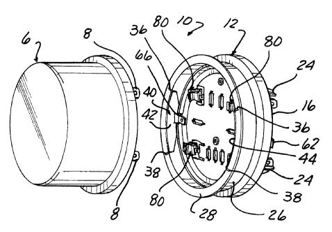
A watthour meter socket adapter 10 having
components constructed in accordance with the teachings
of the present invention is depicted in Figs. 1-10.
As shown in detail in Figs. 1-4, the meter
socket adapter 10, hereafter referred to simply as the
"socket adapter 10" includes a housing 12. Preferably,
the housing 12 is in the form of a one-piece, unitary,
integrally formed component. Preferably, the housing 12
is integrally molded from a suitable electrically
insulating material, such as polycarbonate.
The housing 12 includes a generally planar base
14 having a peripheral edge 16. A plurality of
apertures, each denoted by reference number 18, are
formed in the base 12 at the standard watthour meter
blade terminal connection positions. A three phase
arrangement of apertures 18 is depicted by way of example
only in Figs. 1-4.
Each aperture 18 has the shape shown in Fig. 2
on the front surface of the base 14 with a large outer
portion and two smaller end portions. Each aperture 18
further extends through the base 14 between a front
surface and a rear surface which is depicted in Figs. 3
and 4. On the rear surface of the base 14, each aperture
18 includes a pair of opposed, shallow recesses 20 and 22
formed therein. The recesses 20 and 22 extend from the
rear surface of the base 14 for a prescribed distance
CA 02237397 1998-OS-12
12
through the base 14; but not fully to the front surface
of the base 14.
A plurality of spaced projections or meter feet
24 are formed in the base 14 and extend outward from the
rear surface thereof. The meter feet 24 are provided at
the four outermost aperture 18 positions in a
conventional manner.
An annular side wall 26 integrally extends from
the peripheral edge 16 of the base 14 for a short height
or distance. The annular side wall 26 terminates in a
mounting flange 28 having a radially extending peripheral
edge. The mounting flange 28 mates with a corresponding
mounting flange on a watthour meter and receives a
sealing ring, not shown.
The height or length of the side wall 26 is
substantially shorter than in previously devised socket
adapters to provide a low profile to the socket adapter
10. The height difference between the side wall 26 and a
prior art side wall is 1 15/32 inches. This causes the
meter mounted in the socket adapter 10 to extend outward
from the socket only 1/32 inches not the 2 1/2 inches in
prior adapters.
A unique feature of the present invention is
shown in Fig. 2 wherein a breakaway portion 30 is formed
in the mounting flange or rim 28. Reference number 30
depicts a score line, recess or narrowed thickness
section on the mounting flange 26. As shown in Fig. 2,
the breakaway section 30 extends in approximately a 180°
arc over the periphery of the flange 28. The breakaway
portion 30 can be removed by means of a suitable tool to
enable the meter socket adapter 10 to be used with a
ringless style watthour meter socket cover having a small
diameter opening.
The meter socket adapter 10 of the present
invention also has a unique ground surge means mounted
therein. As shown in Figs. 1 and 2, at least one pair of
slots 36 and 38 are formed in the mounting flange 28.
CA 02237397 1998-OS-12
13
The slots 36 and 38 are spaced apart on the mounting
flange 28 and extend from an inner edge of the mounting
flange 28 at the juncture of the inner surface of the
mounting flange 28 and the side wall 26 to a termination
short of the peripheral edge of the mounting flange 28.
In a preferred embodiment, two pairs of slots 36 and 38
are formed on the mounting flange 28, each pair of slots
generally diametrically opposed from the other pair of
slots as shown in Figs. 1 and 2.
As shown in Figs. 1 and 2, and in greater
detail in Fig. 5, at least one and preferably two
identical surge ground conductors 40 are diametrically
mounted opposite each other on the mounting flange 28.
Each surge ground conductor 40 is removably mounted in
one pair of slots 36 and 38 and includes an arcuate wall
portion 42 which conforms to the inner diameter of the
annular side wall 26 of the housing 12. The arcuate wall
portion 42 has an upper edge 44 and a lower edge 46. A
pair of radially extending tabs 48 and 50 are formed on
opposite side ends of the arcuate wall portion 42
generally adjacent the upper edge 44. Each tab 48 and 50
has a lower edge 52 which seats in a lower portion of the
slots 36 and 38 on the mounting flange 28 of the socket
adapter housing 12. A notch 54 is formed in each tab
contiguous with the lower edge 52 as shown in Fig. 5.
Each tab 48 and 50 has an upper edge 56 extending at an
angle away from the planar lower edge 52 so as to dispose
the top edge 44 of each surge ground conductor 40
slightly above the upper edge of the mounting flange 28.
This places the upper edge of each surge ground conductor
at a position to electrically engage a ground terminal
mounted on the rear surface of a conventional watthour
meter.
Each surge ground conductor 40, shown in Fig.
35 5, has a cutout 60 formed in the lower edge 46. A
movable mounting foot or tab 62 is pivotally connected by
fingers 64 to the lower edge 46 of the arcuate wall
CA 02237397 1998-OS-12
14
portion 42. The mounting foot 62 has a generally planar
shape as shown in Fig. 5. Opposite from the mounting
foot 62 and contiguous therewith is a second planar
portion 66 having an optional aperture 68 formed therein.
As shown in solid in Fig. 5, in an initial,
premounted state, the mounting foot 62 and contiguous
flange 66 are generally in-line with the annular side
wall 42 of each surge ground conductor 40. The mounting
foot 62 is designed to be slidably inserted through an
aperture 70 formed at the juncture of the base 14 and the
annular side wall 26 of the socket adapter housing 12.
Two slots 70 are diametrically formed in the housing 12
as shown in Fig. 3. One mounting foot 62 is inserted
through one slot 70 after being bent generally
perpendicular to the annular side wall 42 as shown in
phantom in Fig. 5 until the foot 62 is disposed in
proximity with the base 14 of the housing 12 to securely
attach each surge ground conductor 40 to the housing 12.
At the same time, the pivotal or bending
movement of the mounting foot 62 also causes a pivotal
movement of the flange 66 to a radially inward extending
position within the housing 12 as also shown in phantom
in Fig. 5. In this position, the flange 66 is located to
provide an easy connection with an electrical conductor
to connect the electrical conductor to the surge ground
conductor 40. Further, the flange 66 is preferably
configured to receive a slide-on, quick connector
attached to one end of an electrical conductor. By
use of the integral mounting foot 62, each surge ground
conductor 40 may be securely attached to the socket
adapter housing 12 without the need for a separate
fastener, rivet, etc., as required in previously devised
surge ground conductors used in meter socket adapters.
The socket adapter 10 also includes a plurality
of jaw contacts each denoted generally by reference
number 80 in one embodiment of the invention.
Preferably, the jaw contacts 80 are identically
CA 02237397 1998-OS-12
constructed as described hereafter. Four jaw contacts 80
are shown in Figs. 1 and 2 for use in a single phase
socket adapter 10. Additional jaw contacts 80 would
obviously be employed for three phase applications.
5 As shown in detail in Fig. 6, each jaw contact
80 is preferably formed of a single, one-piece
electrically conductive member which is folded or bent at
an end 82. The two side by side, planar portions form a
lower blade terminal portion 84 on each jaw contact 80.
10 A first generally rectangular aperture 86 is formed in a
lower end of the blade terminal portion 84. At least
one, and preferably a pair of smaller diameter, second
apertures 88 are also formed in the blade terminal
portion 84 and extend through each contiguous side
15 portion thereof. The second apertures 88 are located at
an opposite end of the blade terminal portion 84 from the
end 82 as shown in Fig. 6.
The generally planar blade terminal portion 84
extends from the lower end 82 to an intermediate juncture
point 90. From the juncture point 90, each side element
of the jaw contact 80 curves radially outward to form an
arcuate end portion 92 which curves radially inward
toward the opposed element before being formed into a
series of generally planar sections 94 which terminate in
an angularly outwardly extending end portion 96. The
flat portions 94 and outer end portions 96 form a jaw end
which is sized to securely, yet releasibly receive a
blade terminal 8 on a meter 6 shown in Fig. 1.
According to the present invention, a unique
jaw contact connector 100, shown in a first embodiment in
Figs. 7-9, is used to securely mount each jaw contact 80
in the housing 12. The connector 100 is formed of
suitable material, such as a metal and, preferably, a
spring metal, such as a spring steel or steel alloy. The
connector 100 is formed with a base or end portion 102.
A centrally located hook 104 extends from one edge of the
base 102. The hook 104 has a generally U-shaped
CA 02237397 1998-OS-12
16
configuration as shown in Fig. 9. An end leg 106 of the
hook 104 is designed to engage the recess 20 formed on
the back surface of the base 14 after the hook 104 has
been inserted through one of the apertures 18 and then
moved laterally sideways in the aperture 18.
At least one and, preferably, a pair of spring
tabs 108 extend angularly from the base 102 on opposite
sides of the central hook 104. When the connector 100 is
mounted in the housing 12, as described above, the spring
tabs 108 extend angularly into the aperture 18 in the
base 14 of the housing 12 and are disposed in a position
to engage the blade terminal portion 84 of the jaw
contact 80 when the jaw contact 80 is slidably inserted
through the aperture 18. The spring tabs 108 snap into a
aperture 88 on the jaw contact 80 to fixedly hold the jaw
contact 80 in the aperture 18.
An optional, but preferred post 110 is also
formed on the connector 100 and extends from one edge of
the base 102 opposite from the hook 104. As shown in
Fig. 7, the post 110 is generally centrally located on
the base 12 and extends perpendicularly from the base
102. The post 110 has an aperture 112 formed therein.
The post 110 is sized to slidably receive a quick
connector, not shown, attached to an external conductor
to enable the external conductor to be easily
electrically connected to a jaw contact 80.
The connector 100 also includes a pair of outer
end legs 114 and 116. Each outer end leg 114 and 116
extends laterally outward from one edge of the base 102.
Each outer end leg 114 is generally spaced from one of
the spring tabs 108 as shown in Fig. 7. Each outer end
leg 114 and 116 has a central notch 118 formed therein.
Each notch 118 is sized to receive one side edge of one
jaw contact 80, as shown in Fig. 8, to position the jaw
contact 80 in the connector 100.
Further, each outer end leg 114 and 116 has a
raised central portion denoted by reference number 120
CA 02237397 1998-OS-12
17
which is contains the notch 118. The raised central
portion 120 is formed by an upper flat formed between two
angular portions, one extending from the base 102 and the
other forming a free end. This causes the raised central
portion 120 to act as a biasing spring to urge the jaw
contact 80 into a good electrically conductive position.
In assembling each jaw contact 80 and its
associated connector 100, the hook 104 of each connector
100 is initially inserted through the aperture 18. The
connector 100 is then moved laterally sideways with
respect to the aperture 18 to bring the end 106 of the
hook 104 into secure registry with the recess 20 formed
in the back surface of the base 14. Next, the blade
terminal portion 84 of a jaw contact 80 is inserted
through the aligned notches 118 in the connector 100 and
into the aperture 18 in the base 14 of the housing 12.
An insertion force is necessary when the juncture point
90 of the jaw contact 80 initially contacts the raised
central portions 120 of the outer end legs 114 and 116 to
overcome the biasing force generated by the raised
central portion 120. Such insertion force is applied to
continue to slidably urge the jaw contact 80 through the
aperture 18 until the spring tabs 108 engage and snap
laterally into the second smaller apertures 88 in the
blade terminal portion 84 of the jaw contact 80 to lock
the jaw contact 80 in the connector 110 and in the
housing 12.
An alternate embodiment of the connector 130 is
shown in Fig. 10. A connector 130 is substantially
identical to the connector 110 described above in that it
includes a base 102, a central hook 104, a pair of spaced
spring tabs 108, and a pair of outer end legs 114 and
116. As in the connector 100, a mounting post 110
extends perpendicularly from the base 102 to provide a
connection for a quick connector attached to one end of
an external electrical conductor.
CA 02237397 1998-OS-12
18
In this alternate embodiment, a second pair of
laterally extending legs 132 and 134 are also formed on
the connector 130, generally integral with the base 102.
The second legs 132 and 134 are generally aligned with
the outer end legs 114 and 116, but extend laterally
outward from an opposite edge of the base 102. Further,
the second end legs 132 and 134 have a raised central
portion 136 which provides a biasing force in the same
manner as the raised central portion 120 on the outer end
legs 114 and 116. The raised central portions 136 of the
second legs 132 and 134 are positioned to electrically
engage external contacts on a member, not shown,
mountable in the socket adapter housing 12, such as a
circuit board having contact pads located at positions
engageable with the raised central portions 136 of the
second legs 132 and 134. The biasing force created by
the raised central portions 136 ensures secure electrical
contact between the external member and the connector 130
and thereby the jaw contact 80.
This unique jaw contact connector mounting
arrangement provides a simple and expedient means for
mounting a jaw contact in a housing of a meter socket
adapter. The use of the separate connector eliminates
the conventional cotter pin and associated labor required
to mount the cotter pin through the blade terminal
portion of each jaw contact while holding the jaw contact
in position through the aperture in the base of the
socket adapter housing. This connector arrangement also
enables the blade terminal portion of each jaw contact to
be made shorter thereby reducing the overall
length/height of the meter socket adapter.
In another embodiment of the present invention
shown in Figs. 11-16, a jaw blade contact 150 is
mountable in the socket adapter 10. The jaw blade
contact 150 includes a bus bar denoted generally by
reference number 152 and a spring clip denoted generally
by reference number 154.
CA 02237397 1998-OS-12
19
The bus bar 152 is formed of a suitable
electrically conductive material, such as copper or
copper plated aluminum. The bus bar 152 has a first or
blade end 156 having a generally planar configuration. A -
plurality of apertures 158, 160 and 162 are axially
spaced along the length of the first end of the bus bar
152. The intermediate aperture 160 is sized and
positioned to receive a dimple or projection described
hereafter on the spring clip 154. The aperture 162 is
positioned to receive a rivet 184 for securely attaching
the spring clip 154 and the bus bar 152.
A pair of opposed flanges 164 and 166 project
angularly, and preferably perpendicularly, from the first
end portion 156 of the bus bar 152. As shown in Figs. 11
and 12, the flanges 164 and 166 are generally
intermediate the opposed ends of the bus bar 152. The
flanges 164 and 166 fill the opening of one slot 18 in
the base 14 of the socket adapter housing 12, as
described hereafter.
The bus bar 152 has a second end 170 which is
angularly offset by an angled portion 172 from the first
end 156. An angled tip 174 extends angularly from the
plane of the second end 170 to form a guide for insertion
of a blade terminal adjacent to the bus bar 152 as also
described hereafter.
The spring clip 154 is shown in detail in Figs.
11, 13 and 16 and is preferably formed of a suitable
spring material, such as spring steel. The spring clip
154 has a center portion 180 with a central aperture 182
formed therein alignable with the aperture 162 in the bus
bar 152 and sized to receive a rivet 184 shown in Fig.
13, to securely and fixedly mount the spring clip 154 to
the bus bar 152.
A first end of the spring clip 154 extends from
the center portion 180. Preferably, the first end is
formed as a spring for exerting a biasing force on a
blade terminal inserted between the first end and the
CA 02237397 1998-OS-12
second end 170 of the bus bar 152. In a preferred
embodiment, the first end of the spring clip 154 is
formed of first and second spaced legs 186 and 188 which
are separated by an intermediate slot 190. Each of the
5 first and second legs 186 and 188 is substantially
identically shaped except for differences in overall
length and width, the purpose of which will be described
hereafter. Thus, the first leg 186 extends from the
center portion 180 of the spring clip 154 in a generally
10 arcuate shaped section 192. The arcuate section 192
curves to a contact edge 194 which normally reparably
engages or is closely spaced from the first end 170 of
the bus bar 152 to receive a blade terminal there-
between. The first leg 186 continues to an outwardly
15 angled portion 196 which extends angularly oppositely
from the end 174 of the bus bar 152 to form a jaw for
guiding a blade terminal between the spring clip 154 and
the bus bar 152. A further angled end 197 is formed on
the end of angled portion 196.
20 The second leg 188 is substantially identically
constructed with an arcuate shaped section 195 extending
from the center portion 180 to a second contact edge 198.
An outer end 200 of the second leg 188 extends angularly
outward from the opposed end 174 of the bus bar 152 at
generally the same angle as the end 196 of the first leg
186.
Both of the first and second legs 186 and 188
are cantilevered from the center portion 180 of the
spring clip 154 to exert a spring or biasing force at the
first and second contact points 194 and 198 against a
blade terminal, not shown, inserted between the contact
points 194 and 198 and the adjacent first end 170 of the
bus bar 152. This biasing force biases the blade
terminal into electrical engagement with the bus bar 152.
The rivet 184 mounted through apertures 162 and
182 acts as a pivot point for the legs 186 and 188. The
distance between the rivet 184 and the first contact edge
CA 02237397 1998-OS-12
21
194 on the first leg 186 is different, and preferably
longer, than the distance between the rivet 184 and the
second contact edge 198 on the second leg 188. This
staggers the push in insertion force required to insert a
single blade terminal on a watthour meter between the
first and second legs 186 and 188 which lowers the
overall insertion force required to fully insert a blade
terminal between the first and second legs 186 and 188
and the adjacent bus bar 152. At the same time, the
combined spring force exerted by the first and second
legs 186 and 188 on the inserted blade terminal still
provides the necessary biasing force.
As the spring force exerted by the first and
second legs 186 and 188 is determined by the distance
between the contact edges 194 and 198 from the rivet 184,
it is clear that the second leg 188 shown in Fig. 11 will
generate a higher spring force against a blade terminal
to due to the shorter distance between its contact edge
198 and the rivet 184. The relative force exerted by the
legs 186 and 188 can be adjusted and even balanced by
varying the width of the legs 186 and 188. As shown in
Fig. 11, the first leg 186 has a larger width between
opposed side edges than the width of the second leg 188.
At the same time, the spring force exerted by
the first and second legs 186 and 188 on the blade
terminal forces the blade terminal against the bus bar
152 with sufficient force to enable the bus bar 152
capable of carrying higher current than jaw contacts in
previously devised watthour meter socket adapters. This
eliminates the need to derate the maximum current
carrying capability of a watthour meter socket adapter as
previously required.
The spring clip 154 has a second end 204 in a
form of a cut out frame extending generally planarly from
the center portion 180. The second end 204 has at least
one and preferably a pair of cut outs 206 and 208 which
respectively form first and second arms 210 and 212. The
CA 02237397 1998-OS-12
22
first and second arms 210 and 212 are bent angularly
outward from the plane of the second end 204 as shown in
Figs. 11, 13 and 16. It will be understood that the
spring clip 154 can also be constructed of a single
cantilevered arm.
The dimple 214 is formed in the second end 204
between the cut outs 206 and 208. The dimple 214 acts as
a locator when it is engaged in with the second aperture
16.0 in the first end 156 of the bus bar 152 to fixedly
locate the spring clip 154 relative to the bus bar 152.
Finally, a pair of flanges 216 and 218 are bent
angularly out of the plane of the center portion 180 as
shown in Figs. 11 and 13. The flanges 216 and 218
preferably extend in the same direction from the center
portion 180 as the first and second arms 210 and 212.
Referring briefly to Fig. 13, as is
conventional, a raised boss 220 extends out of the plane
of the base 14 of the socket adapter housing 12. Boss
220 terminates in a top wall 222 spaced from the base 14
of the housing 12. The aperture 18 is formed through the
top wall 220 as described above and shown in Fig. 2. The
boss 220 and the top wall 222 also form an interior
cavity 224 opening to the rear surface of the base 14 as
shown in Fig. 13.
In mounting the jaw contact 150 in the socket
adapter housing 12, the jaw contact 150 is oriented with
the first end 156 of the bus bar 152 facing the base 14
of the housing 12. The first end 156 of the buss bar 152
is urged through the slot 18 in the top wall 222 of the
boss 220. During such insertion, the first and second
arms 210 and 212 on the spring clip 154 are urged inward
toward the second end 204 of the spring clip 154 to
enable the arms 210 and 212 to pass through the aperture
18 in the top wall 222 of the boss 220. When the tip
ends of the first and second arms 210 and 212 clear the
rear surface of the top wall 222, the arms 210 and 212
spring outward to the position shown in Fig. 13. At the
CA 02237397 1998-OS-12
23
same time, the flanges 216 and 218 on the spring clip 154
have been moved into registry with the outer surface of
the top wall 222 of the boss 220. In this position, the
flanges 216 and 218 cooperate with the arms 210 and 212
to securely and fixedly position the jaw contact 150 in
the boss 220 in the socket adapter housing 12 without the
need for any mechanical fasteners. As shown in Fig. 13,
in the mounted position, the first end 156 of the bus bar
152 projects outward from the rear surface of the base 14
enabling the first end 156 of the bus bar 152 to be
easily inserted into engagement with a jaw contact and a
watthour meter socket.
If it is necessary to remove a jaw contact 150
from the housing 12 for repair or replacement, the arms
210 and 212 need only be urged toward the second end 204
of the spring clip 154 to enable the jaw blade contact
150 to be slid through the aperture 18 in the boss 220.
The jaw blade contact 150 shown in Figs. 11-16
can also be employed, with little or only minor
modifications, as a jaw contact in any electrical
apparatus, such as in any type electrical watthour socket
adapter or socket extender or other electrical device
containing a jaw contact adapted to receive a terminal of
a mating electrical device in a snap-in electrical
connection. In such a general application, the spring
clip 154 functions as a first jaw of the jaw contact 150.
The bus bar 152 will usually be shaped as a mating jaw
member having a planar shape as shown in the bus bar 152
or a cantilevered, arcuate shape similar to that of the
spring clip 154.
Further, both of the jaws of such a jaw contact
may have spaced first and second legs at a second end,
each pair of which are integrally joined to a first end
and secured to the other jaw by means of a suitable
fastener, such a rivet. Mating contact edges or points
of opposed legs of the two jaws would be of equal length
CA 02237397 1998-OS-12
24
and longitudinally off-set or spaced from the contact
edges of the spaced pair of mating legs.
Fig. 17 depicts the use of a modified spring
clip 254, similar to the spring clip 154 described above,
with a conventional planar bus bar 252 employed as part
of a jaw contact in a watthour meter socket adapter or
other electrical apparatus. As shown in Fig. 17, the bus
bar 252 has essentially the same configuration as the bus
bar 152 except that it lacks the flanges 164 and 166.
Specifically, the bus bar 252, which is formed of a
suitable electrically conductive material, has a first
blade end 256 with one or more apertures for receiving
suitable fasteners, such as a rivet or a cotter pin for
connection to the spring clip 254 or mounting the entire
jaw contact 250 in the housing of an electrical
apparatus. An angularly offset, generally planar second
end 258 terminates in an angular end 260.
The spring clip 254 has a first end 264 joined
by a rivet 262 to the bus bar 252. A slot 266 divides
the second end of the spring clip 254 into first and
second legs 268 and 270, each springingly extending from
the first end 264. The first and second legs 268 and 270
have first and second contact edges 272 and 274,
respectively. The first contact edge 272 is spaced
farther from the rivet 262 than the second contact edge
274 to offset the terminal push-on force. The first and
second legs 268 and 270 may have identical or different
widths as in the spring clip 154. In Fig. 18, a slot 280
divides the second end of the bus bar 252 into first and
second legs 282 and 284, each opposed from the legs 268
and 276, respectively, of the spring clip 254.
The bilateral jaw contact structure described
above may also be applied to a conventional folded over
jaw contact typically employed in watthour meter sockets
and bottom connected watthour meter socket adapters. As
Figs. 19 and 20, a folded over jaw contact 300 includes a
base 302 typically having an aperture 304 for receiving a
CA 02237397 1998-OS-12
fastener to connect the jaw contact 300 to an electrical
conductor, not shown. Parallel spaced sidewalls 306 and
308 project from opposite sides of the base 302 to upper
ends 310 and 312. Folder over or inward angled legs
5 project from the upper ends 310 and 312, respectively. A
slot 314 is formed in the first sidewall 306 and a
similar slot 316 is formed in the second sidewall 308.
The first slot 314 divides the first sidewall 306 into
first and second legs 318 and 320. Similarly, the second
10 slot 316 divides the second sidewall 308 into first and
second legs 322 and 324. The first legs 318 and 322 are
arranged as a one jaw pair. Second legs 320 and 324 are
arranged as another jaw pair.
In this embodiment, the bilateral or staggering
15 of the contact edges of the legs 318, 320, 322 and 324 is
attained by forming different angles to the inward angled
or folded over portions of each pair of the facing legs
318, 320, 322 and 324. For example, the first legs 318
and 322 on the first and second sidewalls 306 and 308,
20 respectively, are each formed with a first angularly
inward extending portion 328 and 330, respectively. A
generally planar end portion 332 and 334, which is
approximately parallel to the sidewalls 306 and 308,
extends from the end of the inward extending portion 328
25 and 330, respectively. The end portions 332 and 334 are
spaced apart by a short distance to define a first slot
for receiving a blade terminal 336, shown in phantom Fig.
20, therebetween. A first contact edge 338 is formed on
the first leg 318 between the inward extending portion
328 and the end portion 332. Similarly, a first contact
edge 340 is formed on the first leg 322 between the
inward angled portion 330 and the corresponding end
portion 334. The first contact edges 338 and 340 are
aligned for engaging the end of the blade terminal 336 at
the same time during insertion of the blade terminal
therebetween.
CA 02237397 1998-OS-12
26
Similarly, the second legs 320 and 324 also
have inward angled, extending portions 342 and 344,
respectively. Parallel end portions 346 and 348 project
from the ends of the inward extending portions 342 and
344 to define a second slot for receiving the blade
terminal 336 therebetween, the second slot being aligned
with the first slot.
In order to provide bilateral, staggered
contact edge engagement, the length and angle of the
inward extending portions 342 and 344 of the second legs
320 and 324 is made shorter and at a larger angle with
respect to the corresponding sidewall 306 and 308 than
the angles and lengths of the adjacent inward extending
portions 328 and 330 of the first legs 318 and 322. As
shown in Figs. 19 and 20, the contact edges 350 and 352
on the second legs 320 and 324 are spaced closer to the
outer ends 310 and 312 of the sidewalls 306 and 308 than
the first contact edges 338 and 340 of the first legs 318
and 322. In this manner, insertion of terminal 336 into
the jaw contact 300, as shown in Fig. 20, will cause
engagement of the end of the blade terminal 336 initially
with the second contact edges 350 and 352 of the second
legs 320 and 324. Continued insertion of the blade
terminal 336 between the planar end portions 346 and 348
of the second legs 320 and 324 will bring the end of the
blade terminal 336 into engagement with first contact
edges 338 and 340 of the first legs 318 and 322. This
arrangement staggers the insertion force thereby
significantly reducing the maximum or total insertion
force as compared to previously devised jaw contacts.
Fig. 21 depicts another embodiment of a jaw
contact 300' which achieves the same bilateral or
staggered insertion force feature by pairs of different
length legs. Like reference numerals are used in Fig. 21
to refer to identical portions of the jaw contact 300'
and the jaw contact 300 described above and shown in
Figs. 19 and 20.
CA 02237397 1998-OS-12
27
In this embodiment, the second legs 320 and 324
identically constructed as the legs 320 and 324, shown in
Figs. 19 and 20. The first legs 318' and 322' have a
reduced height as compared to the second legs 320 and 324
caused by beginning the folding over of the inward
extending portions of each of the legs 318' and 322' at a
shorter distance from the base 302 on each of the
sidewalls 306 and 308. The angles and lengths of the
inward extending portions of each of the legs 318', 320',
322' and 324' are identical. The staggered insertion
force is achieved by the shorter height of the first legs
318' an 322' as compared to the greater height of the
second legs 320 and 324. As a result, a blade terminal
upon insertion into the jaw contact 300', will first
engage the contact edges 350 and 352 on the second legs
320 and 324 prior to engaging the contact edges on the
first legs 318' and 322'.
As in the preceding embodiment, the width of
the laterally aligned pairs of legs can be varied to
provide any desired insertion force at each step. For
example, the width of the second and fourth legs 320 and
324 can be wider to more evenly balance the force
provided by the other leg pair.
The unique jaw contact structure of the present
invention provides a staggered, bilateral push-on
insertion force which significantly reduces the maximum
push-on insertion force required to fully insert a blade
terminal into the jaw contact. This bilateral jaw
contact arrangement may be applied to conventional jaw
blade contacts as well as conventional folded over jaw
contacts.
In summary, there has been disclosed a unique
watthour meter socket adapter which contains components
designed for a simple and expedient manufacturing of the
watthour meter socket adapter with fewer fasteners than
used in previously devised socket adapters. This
contributes to a faster and less expensive manufacturing
CA 02237397 1998-OS-12
28
process which reduces the overall cost of the watthour
meter socket adapter.