Language selection

Search

Patent 2237746 Summary

Third-party information liability

Some of the information on this Web page has been provided by external sources. The Government of Canada is not responsible for the accuracy, reliability or currency of the information supplied by external sources. Users wishing to rely upon this information should consult directly with the source of the information. Content provided by external sources is not subject to official languages, privacy and accessibility requirements.

Claims and Abstract availability

Any discrepancies in the text and image of the Claims and Abstract are due to differing posting times. Text of the Claims and Abstract are posted:

  • At the time the application is open to public inspection;
  • At the time of issue of the patent (grant).
(12) Patent: (11) CA 2237746
(54) English Title: DOUBLE-ENDED CANTILEVERED BEAM SPRING CONTACT
(54) French Title: CONNECTEUR ELASTIQUE A DEUX PRISES
Status: Deemed expired
Bibliographic Data
(51) International Patent Classification (IPC):
  • H01R 13/05 (2006.01)
  • H01R 13/17 (2006.01)
  • H01R 13/646 (2011.01)
  • H01R 13/646 (2006.01)
(72) Inventors :
  • KOOIMAN, JOHN (United States of America)
(73) Owners :
  • ANDREW CORPORATION (United States of America)
(71) Applicants :
  • ANDREW CORPORATION (United States of America)
(74) Agent: MARKS & CLERK
(74) Associate agent:
(45) Issued: 2001-02-06
(22) Filed Date: 1998-05-14
(41) Open to Public Inspection: 1998-11-21
Examination requested: 1998-05-14
Availability of licence: N/A
(25) Language of filing: English

Patent Cooperation Treaty (PCT): No

(30) Application Priority Data:
Application No. Country/Territory Date
08/859,755 United States of America 1997-05-21

Abstracts

English Abstract


A one-piece electrical connector 10 for corrugated conductors 20, such as used in
radio frequency high power coaxial transmission lines, is disclosed. The connector 10
has a straight, tubular center section 12 that is supported on both ends 14,16 by
cantilevered beams 18. The connector 10 is comprised of a spring material, such as
beryllium copper or phosphor bronze, for a spring type force fit into the corrugated
conductor 20.


French Abstract

Cette invention concerne un connecteur électrique 10 en une pièce pour conducteurs flexibles 20 comme ceux qui sont utilisés dans les lignes de transmission coaxiales haute fréquence et haute tension. Le connecteur 10 présente une partie centrale tubulaire droite 12 comprise entre deux parties de section diminuant en direction des extrémités 14, 16. Le connecteur 10 est constitué d'un matériau élastique, par exemple du cuprobéryllium ou du bronze phosphoreux, de manière à permettre l'insertion par pression dans un conducteur 20.

Claims

Note: Claims are shown in the official language in which they were submitted.


The embodiments of the invention in which an exclusive
property or privilege is claimed are defined as follows:
1. A connector for making an electrical connection
with an inner surface of a corrugated conductor of a
radio-frequency transmission line, the connector comprising:
a generally straight, hollow, cylindrical center section,
having a uniform outer diameter long enough to span at
least one complete corrugation of said corrugated
conductor, having a front end and a rear end, and having a
plurality of longitudinally-extending slits; and
inwardly-projecting beams, supported at their outer ends,
at each end of said center section for supporting said
center section, said center section and said beams
producing a tapered, gradually increasing spring force
against the inner surface of the conductor as the connector
is inserted into the conductor for a high force spring fit
against the inner surface of the conductor for carrying
radio-frequency signals.
2. The connector of claim 1, wherein said beams are
comprised of a spring material.
3. The connector of claim 2, wherein said beams are
comprised of a beryllium copper material or a phosphor
bronze material.


4. The connector of claim 1, 2 or 3, wherein said
beams are formed in one piece with the center section.
5. The connector of any one of claims 1 to 4,
wherein said center section has a uniform inside diameter.
6. A connector-conductor assembly for carrying
radio-frequency signals comprising:
a conductor for carrying radio-frequency signals, said
conductor having a corrugated portion defining a corrugated
inside surface; and
a connector comprising:
a hollow, straight cylindrical center section, having
a uniform outer diameter long enough to span at least
one complete corrugation of said corrugated conductor,
having a front end and a rear end, and having a
plurality of longitudinally-extending slits; and
inwardly-projecting beams, supported at their outer
ends, at each end of said center section for
supporting said center section;
said connector fitting inside said corrugated inside
surface to produce a tapered, gradually increasing, spring
force as the connector is inserted into the conductor for a
high force spring fit with said corrugated inside surface.


7. The connector-conductor assembly of claim 6,
wherein said center section and said beams are formed in
one piece.
8. The connector-conductor assembly of claim 7,
wherein said connector is comprised of a beryllium copper
material or a phosphor bronze material.
9. The connector-conductor assembly of claim 7, 8 or
9, wherein said center section has a uniform inside
diameter.
10. A connector-conductor assembly for carrying radio
frequency signals, the assembly comprising:
a conductor having a hollow, generally-tubular corrugated
conductor portion, defining a corrugated inside surface;
a connector, having a generally-hollow, cylindrical center
section with a uniform outer diameter long enough to span
at least one complete corrugation of said corrugated
conductor, having a front end and a rear end,.and having a
plurality of longitudinally-extending slits; and
inwardly-projecting beams, supported at their outer ends,
at each end of said center section for supporting said
center section;
said connector fitting said corrugated conductor potion
with a tapered, gradually increasing spring force as the
connector is inserted into the conductor for a high force


spring fit between said connector and said inside surface
of said corrugated conductor portion.
11. The assembly of claim 10, wherein said center
section has a uniform inside diameter.
12. A method for making a radio-frequency connection
to a corrugated conductor for carrying radio-frequency
signals, the conductor having a corrugated inside surface,
the method comprising the following steps:
providing a connector, said connector having a straight,
cylindrical center section with a uniform outer diameter
long enough to span at least one complete corrugation of
said corrugated conductor;
aligning an end part of said connector with an end part of
said conductor; and
inserting said connector into said conductor so that said
connector is engaged with said inside surface with a
tapered, gradually increasing spring force for a high force
spring fit between said connector and said inner surface.


Description

Note: Descriptions are shown in the official language in which they were submitted.


CA 02237746 1998-0~-14


DOUBLE-ENDED CANTILEVERED BEAM SPRING CONTACT

FIELD OF THE INVENTION
This invention relates generally to electrical connectors and more specifically to
contacts for radio frequency high power coaxial transmission lines.
BACKGROUND OF THE INVENTION
S To increase the flexibility of radio frequency (RF) high power coaxial
transmission lines, the electrical conductors for the lines are often corrugated, i.e.,
fabricated with periodic annular or helical deformations. The uneven surface of such
corrugations, however, makes obtaining a uniform electrical contact with connector
components difficult to achieve. Prior art connectors for such corrugated transmission
10 lines have required multiple pieces, invo'ving a screw-in, clamping or expanding-anchor
type design. Such designs, however, are costly to construct and difficult to employ.
SUMMARY OF THE INVENTION
I have discovered an electrical connector or contact that affords a stable, uniform
electrical contact with a corrugated transmission line, like the transmission lines often
15 used for radio frequency high power coaxial transmission lines. The contact is preferably
one-piece, and therefore less expensive to construct, and easier to use, than multi-piece
prior-art connectors.
The contact of this invention has a generally straight, cylindrical or tubular, center
contact section, which is sufficiently long to span or extend across at least one complete
20 corrugation when the connector is inserted into a corrugated conductor. The contact
section is supported on both ends by cantilevered beams, which are preferably tapered or
angled. At least the beams, and preferably the entire connector, are comprised of a spring
material, such as for example, phosphor bronze or beryllium copper, for a spring-type fit
into the corrugated conductor. The dual cantilevered beams enable the connector, and
25 particularly the contact section, to maintain straightness, concentricity and uniform
contact pressure w'nen inserted into a corrugated conductor.


C: 65805(1#1?X01!.DOC)

CA 02237746 1998-0~-14


BRIEF DESCRIPTION OF THE DRAWINGS
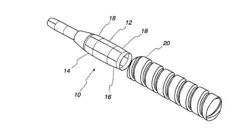
~igure 1 depicts a side view of a spring contact of this invention and a corrugated
conductor assembly.
Figure 2 depicts a cross-section of a spring contact of this invention fitted into the
corrugated conductor assembly of Figure 1.
DETAILED DESCRIPTION OF THE INVENTION
The electrical contact or connector of this invention offers faster and easier
assembly, more uniform contact, and improved performance and stability, when used in
connections for radio frequency high power coaxial transmission lines, than connectors
10 known in the art. The advantages of this invention are obtained by the unique features of
the connector.
Referring to Figure 1, for example, a contact 10 has a center section 12,
comprised of any material with electrical properties suitable for the purposes of the
connector. Usually, non-magnetic materials are preferred to avoid magnetic interference
15 with electrical performance and intermodulation distortion. Section 12 is generally
straight, and tubular or cylindrical in shape, with a hollow interior. Section 12 is
preferably sufficiently long to extend across or span at least one complete corrugation of
the corrugated conductor 20.
The front end 14 and the rear end 16 of connector 10 are supported by
20 cantilevered beams 18 which are tapered or angled. These beams are comprised of any
material with sufficient strength to have spring-like qualities and most preferably are
comprised of the same material as, and in one piece with, center section 12. Phosphor
bronze and beryllium copper are examples of materials particularly suitable for contact
10.
When the contact 10 is inserted or fitted into the corrugated conductor 20, as
shown in Figure 2, the cantilevered beams 18 of connector 10 produce a tapered, or
gradually increasing, spring force for a high force spring fit. Center section 12 spans
across at least one complete corrugation of the corrugated conductor 20 and provides
uniform contact pressure against the conductor 20. The cantilevered beams 18 at both
ends 14 and 16 support the center section 12 so the center section can maintain
straightness and concentricity in the conductor 20. An insulator may be added behind the


C: 65805(1#RX01~.DOC)

CA 02237746 1998-0~-14


beams 18 at end 14 to further support and control the axial position of the contact.
However, the addition of such insulator is not necessary to achieve the full benefits of the
invention.
The principle of the invention and the best mode contemplated for applying that
S principle have been described. It is to be understood that the foregoing is illustrative
only and that other means and techniques can be employed without departing from the
true scope of the invention defined in the following claims.


C: 65805(1~RX01!.DOC~

Representative Drawing
A single figure which represents the drawing illustrating the invention.
Administrative Status

For a clearer understanding of the status of the application/patent presented on this page, the site Disclaimer , as well as the definitions for Patent , Administrative Status , Maintenance Fee  and Payment History  should be consulted.

Administrative Status

Title Date
Forecasted Issue Date 2001-02-06
(22) Filed 1998-05-14
Examination Requested 1998-05-14
(41) Open to Public Inspection 1998-11-21
(45) Issued 2001-02-06
Deemed Expired 2005-05-16

Abandonment History

There is no abandonment history.

Payment History

Fee Type Anniversary Year Due Date Amount Paid Paid Date
Request for Examination $400.00 1998-05-14
Registration of a document - section 124 $100.00 1998-05-14
Application Fee $300.00 1998-05-14
Maintenance Fee - Application - New Act 2 2000-05-15 $100.00 2000-05-02
Expired 2019 - Filing an Amendment after allowance $200.00 2000-10-06
Final Fee $300.00 2000-11-06
Maintenance Fee - Patent - New Act 3 2001-05-14 $100.00 2001-05-03
Maintenance Fee - Patent - New Act 4 2002-05-14 $100.00 2002-05-13
Maintenance Fee - Patent - New Act 5 2003-05-14 $150.00 2003-04-22
Owners on Record

Note: Records showing the ownership history in alphabetical order.

Current Owners on Record
ANDREW CORPORATION
Past Owners on Record
KOOIMAN, JOHN
Past Owners that do not appear in the "Owners on Record" listing will appear in other documentation within the application.
Documents

To view selected files, please enter reCAPTCHA code :


To view images, click a link in the Document Description column. To download the documents, select one or more checkboxes in the first column and then click the "Download Selected in PDF format (Zip Archive)" or the "Download Selected as Single PDF" button.

List of published and non-published patent-specific documents on the CPD .

If you have any difficulty accessing content, you can call the Client Service Centre at 1-866-997-1936 or send them an e-mail at CIPO Client Service Centre.


Document
Description 
Date
(yyyy-mm-dd) 
Number of pages   Size of Image (KB) 
Claims 2000-10-06 4 121
Cover Page 2001-01-08 1 38
Description 1998-05-14 3 109
Claims 1998-05-14 3 121
Drawings 1998-05-14 1 19
Abstract 1998-05-14 1 11
Cover Page 1998-11-25 1 38
Representative Drawing 2001-01-08 1 7
Representative Drawing 1998-11-25 1 7
Correspondence 2000-11-06 1 22
Assignment 1998-05-14 8 262
Prosecution-Amendment 2000-10-26 1 1
Prosecution-Amendment 2000-10-06 7 234