Note: Descriptions are shown in the official language in which they were submitted.
CA 02237793 1998-OS-15
WO 97/18360 PCT/US96/18242 -
INSULATING CONNECTOR RODS USED IN MAKING
HIGHLY INSULATED COMPOSITE WALL STRUCTURES
BACKGROUND OF THE INVENTION
1. FIELD OF THE INVENTION
This invention relates to highly insulative connector rods used to secure
together
multiple layers of insulating and structural material within a composite wall
structure. In
particular, the connector rods secure together an insulating layer and
preferably two
structural layers on either side of the insulating layer. The connector rods
are especially
suited for construction of composite wail structures using the "cast-in-place"
method.
2. THE RELEVANT TECHNOLOGY
As new materials and compositions have been continuously developed, novel
methods for synergistically combining apparently unrelated materials to form
useful
compasites have also been deployed. In the area of building and construction,
high
strength structural walls have been fabricated and then coated or layered with
highly
insulative materials, which generally have relatively low structural strength,
to provide a
composite structure having both high strength and high insulation.
Conventionally, the
structural component, such as a wall, is built first, after which the
insulating layer or sheet
is attached to the structural component. Thereafter a protective cover is
placed over the
insulating material to protect and hide it. The purpose of the insulation
barrier is to
impede the transfer of thermal energy across the structural wall.
One of the least expensive and strongest building materials that has found
extensive use in the construction industry is concrete, which is typically
formed from a
mixture of hydraulic cement, water, and an aggregate, including rocks, pebbles
and sand.
Unfortunately, concrete has the drawback of offering poor insulation compared
to highly
insulating materials such as fiberglass or polymeric foam materials. While an
8 inch slab
of concrete has an R value of 0.64, a 1 inch panel of polystyrene has an R
value of 5Ø
Conversely, highly insulative materials, at least those of reasonable cost,
typically offer
little in terms of structural strength or integrity. Though lightweight
aggregates having
higher insulating ability may be incorporated within concrete to increase the
insulating
effect of the concrete, the use of perlite in an amount that has a dramatic
effect on the
insulation ability of the concrete will usually result in greatly decreased
strength of the
structure.
CA 02237793 1998-OS-15
WO 97/18360 PCT/US96/I8242 -
2
While structural walls made of cement or masonry can be fitted or retrofitted
with
any number of insulating materials, including insulating mats or sheets that
are attached
to the inner wall, or foams that are sprayed between an inner and outer wall,
one strategy
has been to manufacture a composite wall structure having two structural
layers separated
by a core insulating Layer. However, in order for the two-structural-layer
wall to have '
sufficient strength and integrity, and to prevent the two structural walls
from collapsing
together or separating apart during construction and subsequent use of the
building, it is
necessary to structurally bridge the two structural walls together. This has
usually been
accomplished through the use of metal studs, bolts, or beams.
However, because metal is a very good conductive material (and therefore has
very low insulation), such studs, bolts, beams, or other means for
structurally bridging the
two walls together can also create a conduit or conductive thermal bridge
across which
heat can readily flow, notwithstanding their being surrounded by ample amounts
of an
insulating material. As a result, heat can rapidly flow from a relatively warm
inside wall
to a colder outside wall during cold weather, for example. Therefore, though
the
structural walls might be separated by a very efl'rcient insulating material
having a high R
value (which is the measure of the resistance to flow of thermal energy, or
heat, across the
material), the net R value of the overall composite structure will often be
far less when
metal or other noninsulating connectors are used, thus negating or at least
greatly
diminishing the effect of the insulation layer. Of course, one might construct
a building
having no structural supports or connectors between the inner and outer walls;
however,
the result will be a wall having inadequate strength for most building needs.
Examples of composite wall structures using metal tie rods or studs may be
found
in the following U.S. Patents: U.S. Patent No. 4,393,635 to Long, U.S. Patent
No.
4,329,821 to Long et aL, U.S. Patent No. 2,775,018 to McLaughlin, U.S. Patent
No.
2,645,929 to Jones, and U.S. Patent No. 2,412,744 to Nelson. As stated above,
the
composite wall structures disclosed in these references have a substantially
lower R value
than that of the highly insulating layer due to the thermal bridging effect of
the highly
conductive metal studs or connectors that pass through the cross section of
the insulating
layer. '
In order to minimize the problem of thermal bridging, some have employed
connector rods having a metal portion that passes through the concrete layers
and a
thermally insulating portion that passes through the insulating layer {e.g.,
U.S. Patent No.
4,545,163 to Asselin). Others have developed connector rods made entirely from
high R-
value materials. For example, U.S. Patent No. 4,829,733 to Long {hereinafter
the "Long
'733 Patent"} discloses a plastic shear connector used in forming an insulated
wall having
CA 02237793 2003-07-31
*- ' wU 971133601 I'CT/US9G/18242
an inner and an outer concrete structural layer, with a highly insulating
Layer sandwiched
therebetween. Although the plastic shear connector described in the Long '733
Patent has
found some use in the constmction industry, the design of the connector
described therein,
tosether with the method for malting such a connector, create added materials,
manufacturing, and labor costs due to the relatively inefficient method of
forming and then
using the connector set forth in the Long '733 Patent. A summary of the method
used to
manufacture the preferred connector rods disclosed in the Long '733 Patent, as
well as
a summary of the limitations in their use and effectiveness, are set forth
U.S. application Serial No. 08/225,910, filed April 8, 1994 now issued as U.S.
Patent
5,519,973 (hereinafter the Parent Application"). '
One method for manufacturing the composite wall structure described herein is
the so-called "tilt-up" method, whose manufacture is described hereinbelow. An
example
of a preferred connector rod used in the tilt-up method 'is set forth in the
Parent
Application, which connector has a substantially printed tip at one end and an
enlarged
head at the other. Both aid iri the placement of the connector rods compared
to, e.~., the
connector disclosed in the Long '733 Patent. The tilt-up method for
manufacturing
composite wall structures is typically carried out as follows.
First, concrete is poured into a horizontally configured form to form a first
unhardened structural layer. Second, the insulating layer is placed over the
surface of the
still uncured first structural layer. Third, the connector rods arc inserted
through the
exposed horizontal surface of the insulating layer so that a first portion of
the connector
rods extends into the interior of the uncured first structural layer, so that
a second portion
spans the width of the insulating layer, and so that a third portion extends
outwardly from
the insulating layer surface. The connector rods are preferably twisted in
order to
consolidate the uncured concrete into a locking structure or recess within the
first portion
of the connector rod to ensure eventual secure anchoring of the connector rod
within the
first horizontal slab. Fourth, either before or after substantial hardening of
the first
structural layer, a second concrete layer is poured over the surface of the
insulating layer
within a form in order to form the second structural layer. The third portion
of the
connector rods is preferably fully enveloped within the second structural
layer. Fifth, after
the fast and second structural layers have been adequately cured and the forms
removed,
the horizontally positioned composite wall structure is tilted up vertically
by means of a
hoist or crane and positioned into the desired location.
A second method for manufacturing the composite wall structure is the "cast-in-
3 5 place" method, wherein the structural walls are poured within a vertical
form that has been
built in a location at or near where the composite wall structure is to be
finally located.
CA 02237793 1998-OS-15
WO 97/18360 PCT/LTS96/18242
4
A more detailed discussion of this method is set forth more fully hereinbelow.
In the cast-
in-place method, connector rods having a length corresponding to the width of
the entire
composite wall structure are placed substantially orthoginaiIy through the
insulating layer,
with a first portion extending out of one surface of the insulating layer, a
second portion
extending through the width of the insulating layer, and a third portion
extending out the °
other surface of the insulating layer. The insulating layer with the connector
rods
extending out of both surfaces is then placed vertically between the vertical
form. The
extended portions of the connector rods horizontally span the form and
maintain the
insulating layer in a properly spaced arrangement between the two walls of the
form, with
vertical spaces between each side of the insulating layer and the form where
the structural
material is to be poured. Thereafter, concrete or other hardenable structural
material is
poured between the two vertical spaces to form a structural layer on either
side of the
insulating layer. Upon curing and removal ofthe form, the structural layers
and insulating
layer are locked together by means of the connector rods to form the composite
watt
structure.
While the connector rods disclosed in the Long '733 Patent could be used in
the
cast-in-place method, they have the serious drawback of having flat,
substantially
rectangular end surfaces. This design has at least three drawbacks: (1) the
rectangular
end surfaces of the connector rods of the Long '733 Patent together with the
relatively
sharp corners of the rectangular ends can cause fi-iction or hang-ups between
the
rectangular surface and the side walls of the forms when placing the
insulating layer
vertically in the form; (2) upon removal of the form fi-om the composite wall
structure, the
exposed rectangular end surfaces of the connector rods will likely present a
visual
nuisance and the exposure through the composite wall surface can cause the
connector
rods to be exposed to potentially destructive environmental elements, such as
chemical
or solar attack; and {3) the rectangular volume occupied by the connector rods
of the
Long '733 Patent will tend to inhibit good consolidation of the concrete in
the wall
surface at or near the area around the rectangular end surfaces, particularly
just beneath
the flat portion of the connector rod abutting the sidewall surface of the
form.
In light of the foregoing, what are needed are improved insulating connector
rods
and methods for manufacturing highly insulative composite wall structures.
In addition, what are needed are improved designs and methods for molding
improved insulating connector rods in a single step that yet provide adequate
strength and
support in the manufacture of composition wall structures.
Additionally, what are needed are improved connector rods having a design that
eliminates or at least greatly diminishes the tendency of either or both ends
of the
CA 02237793 1998-OS-15
WO 97/18360 PCT/IJS96/18242 -
connector rod to be exposed on the composite wall surface, particularly when
utilized in
the cast-in-place method for manufacturing highly insulating composite wall
structures.
What are further needed are improved connector rods that have a design which
reduces the friction between the ends of the connector rods and the sidewalls
of the forms
5 during placement of the insulating layer within the form.
Finally, it would be an improvement in the art to provide improved connector
rods
having a design which improves the ability to achieve substantially complete
consolidation
of the concrete or other hardenabie structural material in the outer surfaces
of the
structural layers, particularly at or near where the outer ends of the
connector rods are
oriented.
Such improved connector rods having improved design features and methods for
manufacturing such connector rods having the aforesaid design features are set
forth and
claimed herein.
SUMMARY OF THE INVENTION
The present invention relates to improved designs and methods for
manufacturing
connector rods used in the manufacture of composite wall structures. In
particular, such
connector rods can be manufactured, at least substantially, in a single step
and may be
used in the manufacture of highly insulating wall structures having two
concrete structural
layers surrounding a highly insulating material sandwiched therebetween. Such
wall
connectors prevent or greatly reduce the flow of heat between the two concrete
walls
surrounding the insulative material, and also eliminate the tendency of one or
both of the
ends to be exposed within the surface of the final composite wall structure.
In addition,
the connector rods of the present invention reduce friction or potential hang-
up between
the connectors and the form sidewalls during placement of the insulating layer
between
the form sidewalls using the cast-in-lace method. They also promote better
consolidation
of concrete or other hardenable structural material in the outer surfaces of
the structural
layers, particularly at or near where the outer ends of the connector rods are
oriented.
These features have been accomplished by designing and manufacturing a
connector rod having a substantially pointed tip at both ends. Such connectors
rods are
generally symmetrical and/or simple in design and construct, which allows them
to be
molded in a single step, such as by injection molding, resin transfer molding,
or reaction
injection molding, thereby eliminating the need to form the connectors in a
mufti-step
fashion as has been the standard in the art for plastic connectors similar in
design and
construct to those disclosed in the Long '733 Patent.
CA 02237793 1998-OS-15
WO 97/18360 PCT/US96118242
6
In a preferred embodiment, the connector rod is injection molded from a
polycarbonate resin or other high strength resin or moldable plastic material.
Another
preferred material is a polycarbonate "alloy" consisting of polycarbonate and
polybutyiene
teraphthalate. In some cases, where increased tensile and bending strength are
desired,
fibers such as glass fibers, carbon fibers, mineral fibers, boron fibers,
ceramic fibers, and '
the like may be impregnated within the resin to form a connector rod having
increased
strength and stiffness. The use of more flexible fibers, such as cellulosic,
nylon, or other
polymeric fibers would be expected to increase the toughness and decrease the
stiffness
ofthe connector rod. Nevertheless, where fibers are unnecessary it will be
preferable not
to use them due to the generally increased cost of their use.
In a preferred embodiment, the connector rod has a central shaft having at
either
end a substantially pointed tip, which facilitates the entry of the connector
rod through the
insulating layer, and which also ensures that there is only minimal contact
between either
end of the connector rod and the sidewalls of the form when used in
manufacturing
composite wall structures using the cast-in-place method. Of course, the
connector rods
disclosed and claimed herein are not limited to any particular method and may
be used,
for example, in the tilt-up method of manufacturing composite wall structures
(although
the connector rod having an enlarged head at one end, as in the Parent
Application, is
preferred). The combination of pointed tips at both ends of the connector rod
greatly
facilitates the use of the connector rod in the manufacture of composite wall
structures
and leads to a superior final product in which only a minimal amount of the
connector rod
is exposed within the composite wall surface. It also aids in placing the
insulating layer
between the form sidewalk and promotes better consolidation of the concrete or
other
hardenable structural material.
The central shift includes a middle portion, or "mesial segment", which is
intended
to reside within the insulating layer. The mesial segment is preferably
designed to greatly
reduce or prevent the incursion of concrete or other flowable structural
material around
the mesial segment and into the interior of the volume defined by the
insulating layer.
Such an influx of concrete into the insulating layer will create a thermal
bridge through
that portion of the insulating layer, which will reduce the overall insulating
ability, or R-
value, of the composite wall structure.
For purposes of clarity, the segment of the connector rod that includes the
pointed
tip that actually penetrates the insulating layer will hereinafter be referred
to as the
"penetrating segment", while the remaining segment that includes the other
pointed end
that does not penetrate the insulating layer will be referred to as the
"trailing segment".
CA 02237793 1998-OS-15
WO 97/18360 PCT/US96/18242
7
The substantially pointed ends within the penetrating segment of the connector
rods ofthe present invention make it far quicker and easier for the technician
to insert the
connector rods through the insulation layer compared to, e.g., connectors
having a
rectangular cross-section on both ends, which design is commonly used in the
industry.
In addition, the substantially pointed end allows for easy penetration through
an insulating
material that has a greatly reduced hole size drilled therethrough, or even
none at all, since
the substantially pointed end makes the connector rod "self tapping".
Alternatively, the
end could have a pyramidal (3-, 4-, or mufti-faceted) shape rather than a
conical tip and
still fall within the definition of "substantially pointed". The result would
be substantially
I O the same in each case. A wedge-shaped or "chisel" end, which closes up to
a line rather
than a single point, would be less satisfactory, but superior to the
rectangular surface of
the prior art connectors.
The connector rod further includes one or more recessed portions in both the
penetrating segment and the trailing segment into which the uncured concrete
or other
structural material will flow during casting of the structural walls. Upon
hardening, the
concrete or other structural material within the one or more recessed portions
will fcrmly
and reliable anchor the connector rod firmly within the structural layers of
the composite
wall structure. Vibrational forces applied to the form or "poking" with rods
can be
employed to help consolidate the concrete forming the structural walls.
~ On either end of the mesial segment, which is defined as that portion of the
connector rod that resides within the insulating layer, is a flange or other
means for
locking the connector rod in place after being inserted through the insulating
layer. One
of the flanges can be integrally molded into the connector rod, although it
can also
comprise a plastic washer or disk that is slid over the connector shaft either
before or after
the connector rod is placed into the insulating layer. It is far simpler and
cheaper for the
flange at or near the interface between the mesial segment and trailing
segment, which is
opposite to the side of the connector being inserted through the insulating
layer, to simply
be integrally molded within the connector rod. This first, or prefixed, flange
acts as a
means for orienting the connector rod by limiting the depth of penetration
through the
insulating layer.
However, it is preferable that the flange at or near the interface between the
mesial
segment and the penetrating segment that is inserted through the insulating
layer to be
attached after inserting the connector rod through the insulating layer.
Otherwise, this
flange might tear too large of a hole through the insulating layer and create
the possibility
of back flow of uncured concrete or other structural material into the
enlarged hold,
thereby creating a thermal bridge in the vicinity of the incursion. The second
flange
CA 02237793 1998-OS-15
WO 97/18360 PCT/US96/18242 -
8
preferably comprises a plastic washer that is simply snapped onto the
connector rod after
it has been inserted through the insulating layer. It may be locked into place
by any
known means, such as fitting into a small groove or recess within the central
shaft at or -
near the interface between the mesial segment and the penetrating segment. The
hole
within the plastic washer will preferably be slightly smaller than the
circumference of the '
penetrating segment, but because the washer will typically be slightly
flexible, it will be
possible for the hole in the washer to temporarily expand when the washer is
inserted over
the penetrating segment and then contract after it reaches the locking groove
or recess to
become locked in place.
Alternatively, the plastic washer might have, e.g., an elliptical hole that
corresponds to an ellipsoidal proflIe of the connector rod. The locking grove
or recess
at or near the interface between the mesial segment and the penetrating
segment might be
somewhat more circular than elliptical, such that when the plastic washer is
twisted
relative to the connector rod, it becomes locked in place. Rotating the washer
back the
I 5 other way unlocks the washer for easy removal.
The washer might also simply be a self locking washer that is press-fitted
over the
connector rod without a locking groove or recess. The washer is held in place
due to the
pressure of the inner wall against the outer surface of the connector rod. It
is pushed on
until it reaches the insulating layer, thereby causing the connector rod to be
locked in
place. The washer can be adapted with little cuts around the interior wall in
order to
allow the inner wall to flex somewhat when being inserted over the connector
rod.
Finally, although plastic washers are preferred, the washers can be made of
any
material that allows the locking of the connector rod in place after being
inserted through
the insulating layer. Because the washer is located on the outer surface of
the insulating
layer it can be made of, e.g., metal without adversely affecting the
insulating ability of the
insulating layer.
BRIEF DESCRIPTION OF THE DRAWINGS
Figure lA is an exploded perspective view of a preferred insulating connector
rod
having a substantially pointed tip at either end shown being fitted with a
locking device.
Figure 1B is a perspective view of the connector rod of Figure 1 A having been
fitted with the locking device.
Figure 1 C is an exploded perspective view of an alternative insulating
connector
rod having a substantially pointed tip at either end shown being fitted with a
locking
device.
CA 02237793 1998-OS-15
WO 97/18360 PCT/US96118242 -
9
Figure 2 is an exploded perspective view of an alternative embodiment of a
connector rod ofthe present invention being fitted with an orienting device
and a locking
device.
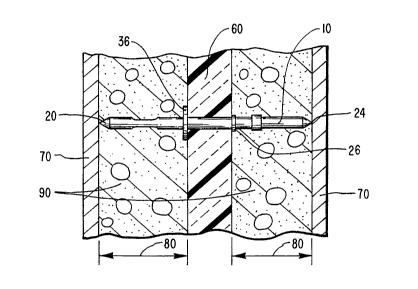
Figure 3A is a cross-section view of composite wall structure formed using the
cast-in-place method and one of the connector rods of Figure 1.
Figure 3B is a breakaway perspective view of the composite wall structure of
Figure 3A showing minimal exposure of one end of the connector rod through the
composite wall surface.
Figure 4A is a breakaway perspective view showing the use of a prior art
connector in a composite wall structure.
Figure 4B is a breakaway perspective view of a side of the structural layer of
a
composite wall structure made by the cast-in-place method using the connector
shown in
Figure 4A and showing the increased exposure of one end of the connector rod
through
the composite wall surface.
DETAILED DESCRIPTION OF THE PREFERRED EMBODIMENTS
The present invention relates to specially designed, highly insulative
connector
rods used in the manufacture of composite wall structures, and methods for the
manufacture and use of such connector rods. Such connector rods can be
manufactured
in a single step to yield connector rods having a wide variety of structural
features and
accessories therein. Such connector rods are designed to secure together two
structural
layers that are separated a predetermined distance by an insulating layer
therebetween
comprising a highly insulating, or high R value, material. Because the
connector rods also
are made from a high R value material, they prevent or greatly reduce the flow
of heat
between the two concrete walls compared to, e.g., metal connectors. The design
of the
connector rods makes them especially useful in the manufacture of composite
wall
structures using the cast-in-place method. However, they are not limited to
any particular
method for manufacturing composite wall structures.
The connector rods of the present invention are preferably injection molded
from
any appropriate resin or other high strength plastic material, although they
may also be
molded by resin transfer molding, reaction injection molding, or any other
single-step or
relatively simple molding process known in the art. An important criterion is
that the
manufacturing costs of the molding process be commensurate with the overall
cost
parameters of the connector rod to be used.
A preferred resinous material is polycarbonate resin because of the ease with
which it may be injection molded. Another similar resinous material is
polycarbonate-
CA 02237793 1998-OS-15
WO 97/18360 PC~'/US96/18242
IO
polybutyIene teraphthalate alloy, which is less expensive than polycarbonate
resins. Other
resins, such as epoxy resins, thermoset plastics, and other high strength,
high R-value
materials, may be used. An important criterion is to select a resinous
material or other
plastic having the desired properties of strength and insulation depending on
the
S performance criteria of the composite wall structure to be fabricated.
Although not necessary in many instances, it may be desirable to incorporate
within the resinous material or other plastic material fibers such as glass
fibers, carbon
fibers, boron fibers, ceramic fibers, and the like in order to increase the
tensile strength,
bending strength, and toughness of the connector rod. Fibers can also increase
the shear
strength of the connector rod if adequately randomly dispersed throughout the
resinous
or other plastic material. Nevertheless, where fibers are not necessary in
order to impart
greater strength or stiffness to the connector rod, it will usually be
preferable to exclude
them due to the generally increased cost of their use.
Because the use of resins or other moldable plastics (whether or not
impregnated
with fibers) allows for an almost endless variety of design co~gurations that
can be
molded into a connector rod in a single step, such connector rods can include
a wide
variety of structural features or accessories without increasing the cost of
manufacture.
Many connector rods presently used in making composite wall structures are
formed by
pull-trading continuous fibers through a resinous material, which thereafter
must be cut,
machined, and then retrofitted with even the most minor additional structural
features due
to the limitations inherent in the pull-trusion method of molding. Pull-
trusion, Like
extrusion, is inherently only capable of yielding rods of uniform cross-
section
corresponding to the die head design.
Referring to Figure lA, in a first preferred design of the connector rod of
the
present invention, the connector rod IO includes an eiongate shaft 12 that is
preferably
cylindrical or ellipsoidal. The elongate shaft 12 includes a penetrating
segment 14, a mesial
segment 16, and a trailing segment 18. The penetrating segment 14 includes a
substantially pointed penetrating tip 20 disposed at a first end of the
connector rod 10 and
at least one recessed portion 22 for receiving flowable concrete or other
hardenable
structural material therein for anchoring the connector rod within the first
structural layer
upon curing or hardening of the structural material.
The trailing segment 18 also includes a substantially pointed tip 24 at the
other end
of the connector rod 10, but is designated as a trailing tip 24 for clarity.
The penetrating
tip 20 and the trailing tip 24 may or may not be identical in size or design
and will often
3 S only be distinguishable in view of the placement, if any, of a fixed ridge
or flange 26
disposed at or near the interface between the mesial segment 16 and the
trailing segment
CA 02237793 1998-OS-15
WO 97/18360 PCT/US96/I8242 -
11
18. In the event that the ridge or flange 26 is not integrally molded Within
the connector
rod I0, but is only later attached later as a plastic washer (Figure 2), the
penetrating tip 20
and trailing tip 24 may very well be indistinguishable before attachment of
the ridge or
flange 26.
The trailing segment 18 also includes means for anchoring the trailing segment
within the second structural layer upon curing or hardening of the structural
material. An
example of structure that would serve this anchoring purpose is a protrusion
28, which
is disposed between the ridge or flange 26 and the trailing tip 24. Hardenable
structural
material can flow into and harden within a recess 30 defined by the portion of
the trailing
segment 18 between the ridge or flange 26 and the protrusion 28.
Alternatively, the
anchoring means could be at least one recessed portion (not shown) similar to
the at least
one recessed portion 22 within the penetrating segment 14.
In a preferred method of use, the ridge or flange 26 will be fixed in place
prior to
placement of the connector rod IO through the insulating layer. This may be
accomplished by integrally molding the ridge or flange 26 within the connector
rod 10, as
shown in Figure lA. Alternatively, the ridge or flange 26 may comprise a
plastic washer
or other appropriate ridge-forming device that is attached onto the connector
rod I O prior
to insertion through the insulating layer (Figure 2). In either scenario, the
ridge or flange
26 provides a definite stopping point, which constitutes means for limiting
the penetration
depth of the connector rod I O through the insulating layer. This helps the
technician place
the connector rod 10 through the insulating layer to the correct depth
quickly, easily, and
accurately virtually every time.
Located at or near the interface between the mesial segment 16 and the
penetrating
segment 14 are means, such as a groove or recess 32, for attaching a locking
device, such
as a plastic washer 34, to form a second ridge or flange 36 at or near the
interface
between the mesial segment 16 and penetrating segment 14, as shown in Figure
iB. This
second ridge or flange 36 provides means for locking the connector rod 10 in
place after
placement within the insulating layer so that it will not pull out or
otherwise shift out of
position once it is properly placed. The means for attaching the plastic
washer 34 at or
near the interface between the mesial segment 16 and penetrating segment 14
comprises
the groove or recess 32 that is configured such that, once the plastic washer
34 is slid over
the penetrating segment 14 and into the groove or recess 32, the plastic
washer 34 will
be reliably secured in place when subject to ordinary loads associated with
placing the
insulating layer within the vertical form and pouring concrete on either side
of the
insulating layer within the form.
CA 02237793 1998-OS-15
WO 97/18360 PCT/CTS96/18242 -
12
Nevertheless, in cases where the technician wishes to remove the connector for
any reason, the locking mechanism provided by the groove or recess 32 and the
plastic
washer 34 can be adapted to allow for such removal. In this scenario, the
groove or
recess 32 and washer 34 may be configured such that they can be locked
together upon
rotating the washer 34 relative to the connector rod 10. This may be done, for
example,
by designing the connector rod 10 to have a generally ellipsoidal profile (not
shown) and
the hole 38 within the washer 34 to be generally elliptical (not shown). The
groove or
recess 32 might be designed to have a more circular profile such that when the
washer 34
is rotated relative to the connector rod 10, the narrower portion of the
elliptical hole 38
will be positioned nearer the widest portion of the surface of the connector
rod 10,
thereby causing the washer 34 to become locked in place (not shown}. Rotating
the
washer 34 in the opposite direction to realign the ellipse of the washer hole
38 and the
elliptical surface of the connector rod 10 would then cause the washer 34 to
be unlocked
from the groove or recess 32 (not shown).
1 S Referring to Figure 1 C, the means for locking the connector rod in place
within
the insulating layer might simply constitute a self-locking washer 42 that is
press-fitted
over a connector rod 40 that is similar to connector rod I O except that it
does not include
the locking groove or recess 32. The washer 42 is held in place due to the
pressure of the
inner wall of the washer 42 against the outer surface of the connector rod 40.
It is pushed
on until it reaches the insulating layer, thereby causing the connector rod to
be locked in
place. The washer may also be adapted with little cuts 44 around the interior
wall in order
to allow the inner wall to flex somewhat when the washer 42 is being inserted
over the
connector rod 40.
Finally, although plastic washers are preferred, the washers 34, 42 can be
made
of any material that allows for reliable locking of the connector rod in place
after being
inserted through the insulating layer. Because the washers 34, 42 are to be
located on the
outer surface of the insulating layer, they can be made of, e.g., metal
without adversely
affecting the insulating ability of the insulating layer and the overall
composite wall
structure.
In an alternative embodiment, the connector rod of the present invention might
be
designed to function equal or similar to the connector rod 50 shown in Figure
2. The
connector rod 50 is similar in design and function to connector rod IO of
Figure lA,
except that the ridge or flange 26 of connector rod 10 has been eliminated and
replaced
with groove or recess 52. In addition, the means for securing the trailing
portion 18 of
connector rod 10 has been modified such that the protrusion 28 has been
eliminated and
CA 02237793 2003-07-31
WU 97/18360 PCT/US9G/18242
13
replaced with at least one recessed portion 54 disposed between the groove or
recess 52
and the trailing tip 24 similar to the at least one recessed portion 22 of
connector rod 10.
Because the connector rod 50 shown in Figure 2 appears to be substantially
symmetrical, the penetrating segment 12 and trailing segment 18 are virtually
indistinguishable until an orienting device, such as one of first and second
washers 56, 58,
is secured to the connector rod 50. In a preferred method of use, the
connector rod 50
is first fitted with the first washer 56, which, when locked in place, will
serve as means for
orienting the connector rod 50 during insertion through the insulating layer.
In particular,
the washer 56 will act as a stop that will limit the degree of penetration of
the connector
rod 50 through the insulating layer. This allows the technician to place each
of the
connector rods 50 through the insulating layer to the same depth every tirrle.
Thereafter,
the second washer 58 is secured in place within the groove or recess 52 at or
near the
intersection of the penetrating segment 14 and mesial segment 16 in order to
provide
means for locking the connector rod 50 in place in the desired orientation
within the
I 5 insulating layer.
Alternatively, the connector rod 50 and washers 56, 58 can be modified to
provide
means for locking and unlocking the washers 56, 58 in place on the connector
rod 50, as
explained above. Similarly, one or both of the grooves or recesses 32, 52 can
be
eliminated and the corresponding washer be adapted to be held in place in a
press-fit
manner. However, it will generally not be preferable to modify the orienting
means in this
manner, since this may make it more difficult to correctly place the orienting
washer 58
in the correct location each time, which might cause varying placement depths
of the
multiple connector rods 50 being placed within the insulating layer.
In general, the connector rods of the present invention, as illustrated above,
are
designed to be especially useful in the manufacture of composite wall
structures using the
cast-in-place method, which is illustrated in Figure 3A using the connector
rod 10
illustrated in Figure 1 A. In this method, an appropriate number of the
connector rods are
inserted through an insulating layer 60 to a depth determined by the location
of the first
ridge or flange 26. Thereafter, formation of the second ridge or flange 36 by
attachment
of washer 34 on the other side of the connector rod I 0 locks the connector
rod 10 in place
in the desired orientation. When the insulating layer 60 is placed between the
sidewalk
70 of a form, the substantially pointed' penetrating tip 20 and trailing tip
24 make
significant abutting contact with the two sidewalls 70, which serve to orient
the insulating
layer 60 at the appropriate distance between the two essentially parallel side
walls 70 in
conjunction with the locking action ofthe first and second ridges or flanges
26 and 36.
In an alternative embodiment, the design of the penetrating tip 20 and
trailing tip 34 can
CA 02237793 1998-OS-15
WO 97/18360 PCT/1JS96/18242 -
14
be changed from a conical shape to a pyramidal shape (not shown) that can be 3-
, 4-, or
mufti-faceted without significantly altering the utility of the connector rods
of the present
invention. However, while a chisel-shaped end (not shown) would likely be
superior to
the rectangular-shaped ends of the prior art connector, they are less
preferred than the
_ conical or pyramide-shaped tips in the preferred connector rods.
Once the insulating layer 60 has been appropriately situated between the form
sidewalls 70, concrete or other hardenable structural material is then poured
within spaces
80 on either side of the insulating layer 60 between the insulating layer 60
and the two
sidewalk 70 to form structural layers 90. In order to avoid unduly stressing
one side of
the insulating layer 60 during formation of the structural layers 90, it is
usually preferable
to pour equal or similar depths of concrete or other structural material
within spaces 80
in order to substantially equalize the pressure being exerted on either side
of the insulating
layer 60 at any particular moment. Once the concrete or other structural
material has
sufficiently cured or hardened, the form sidewalls 70 can be removed from
around the
structural layers 90 of the composite wall structure.
As shown in Figure 3B, an important advantage of using the connector rods of
the
present invention is that little or virtually none of the connector rod tips
(e.g., trailing tip
24) will be exposed within the outer surface 100 of the final hardened
composite wall
structure 110. This is because the connector rods terminate at either end with
~ substantially pointed tips 20, 24 having a cross-section that is essentially
reduced to zero
at the end. This sharply contrasts with the rectangular surface exposure that
will occur
when using the prior art connectors of rectangular cross section, as shown in
Figures 4A
and 4B. This reduced exposure would also be true for chisel-shaped ends, which
would
terminate in a Line rather than a rectangle in the outer surface of the
composite wall
structure (not shown).
The advantage of using the pointed end connector of the present invention is
at
least three-fold: 1) the reduced surface contact between the substantially
pointed tips and
the form sidewalls will greatly reduce the friction vis-a-vis the rectangular-
faced coru~ector
of the prior art, which will facilitate placement of the insulating layer 60
between the
sidewalls 70 ofthe form; 2) upon removal ofthe form sidewall 60 from the
composite wall
stn.icture 110, only the pointed ends 20, 24 of the connector rods will be
exposed within
the composite wall surface 100, which greatly reduces or eliminates potential
visual
nuisance and greatly reduces exposure of the connector rods to potentially
destructive
environmental elements, such as chemical or solar attack; and 3) the reduced
cross section
at the interface between the substantially pointed connector rods of the
present invention
and the sidewalls 70 facilitates more complete consolidation of the concrete
or other
CA 02237793 1998-OS-15
WO 97/18360 PCT/US96/18242 -
structural material of the outer wall surface 100 in or near the area around
the pointed tips
compared to, e.g., a rectangular-faced prior art connector, which would tend
to prevent
complete consolidation of concrete just beneath the flat portion of the
connector abutting
the sidewalls 70.
5 In general, the stntctural material used to form the structural layers 90 of
the
composite wall structures made according to the present invention may comprise
any
suitable material which can flow when initially cast and then harden to form a
generally
rigid, structural layer. In a preferred embodiment, the structural layers
comprise a
concrete material formed from a mixture including hydraulic cement, water, an
aggregate
10 material, and other appropriate admixtures. Concrete is preferred because
of its low cost,
high strength, and ease of casting compared to other materials. Nevertheless,
any
appropriate structural material may be used, such as high strength polymers,
resins or
other materials, which can flow when cast and later be hardened.
The insulating layer 60 may comprise any appropriate insulating material, such
as
15 polystyrene foam, fiberglass, aerogel, xerogel, xonotlite, seageI,
polyisocyanate foam,
polyurethane foam, urea-formaldehyde foam, and low density, highly insulating
cementitious materials. Such insulating materials are given only by way of
example and
not by limitation.
The insulating layer 60 preferably includes a plurality of holes that are
predrilled
or punched therethrough through which the connector rods of the present
invention can
be inserted, as described above. Because of the piercing effect of the
penetrating tip 20,
it is often preferable to drill holes having a smaller diameter compared to
the diameter of
the elongate shaft 12 to ensure a tight fit within the insulating layer. This
helps to prevent
incursion of concrete into the insulating layer, which can cause a thermal
bridge, and
undermine the utility of the present invention. In many cases, no holes will
be required
at all because of the self tapping nature of the substantially pointed
penetrating tip 20.
The various connector rods described herein were used in experimental
composite
wall structures and were found to have more than adequate shear strength to
hold
together the three layers of the composite wall structures that were tested.
In fact, in all
cases when a stress strong enough to cause a failure of the composite wall
structure was
applied, it was the concrete structural layer that failed in each instance.
The connector
rods were left intact.
The present invention may be embodied in other specific forms without
departing
from its spirit or essential characteristics. The described embodiments are to
be
considered in all respects only as illustrative and not restrictive. The scope
of the
invention is, therefore, indicated by the appended claims rather than by the
foregoing
CA 02237793 1998-OS-15
WO 97/18360 PCT/iT896/18242 -
16
description. All changes which come within the meaning and range of
equivalency of the
claims are to embraced within their scope.