Note: Descriptions are shown in the official language in which they were submitted.
CA 02238038 1998-05-19
WO 97/18990 PCTrUS96118578
TITLE
STAGGERED ACTUATION OF ELECTROMAGNETIC TILES
FOR BOUNDARY LAYER CONTROL
CROSS-REFERENCE T0 RELATED APPLICATION
This application claims the benefit of U.S.
Provisional Application No. 60/007,379, filed November
20, 1995.
BACKGROUND OF THE INVENTION
Field of the Invention
The present invention relates to controlling the flow
o~ a ~luid along a wall using multiple electromagnetic
tiles and, more particularly, to an improved actuation
technique and alternate geometry for an array of such
tiles that provides extremely e~icient control o~ the
boundary layer along the wall.
CA 02238038 1998-0~-19
WO 97/18990 PCT~US96/18S78
Descxiption o~ the Related Art
A viscous fluid, and a body completely immersed in the
fluid, form a boundary layer at the body's surface when
the ~luid and the body move relative to each other.
That is, the layer of fluid in contact with the body is
essentially at rest, while in an area spaced from the
body, the fluid moves at its ~ree-stream velocity. The
region between the body and that area is known as a
boundary layer.
The boundary layer is l~m~ n~ ~ at low Reynolds' numbers.
(Re = UL/v, where U is a characteristic velocity, such
as the free-stream velocity, L is a characteristic
~lm~n~ion of the body, such as the length of a wing
chord or boat hull, and v is the kinematic viscosity of
the fluid.~ When the Reynolds' number increases, the
boundary layer becomes unstable and turbulent. In some
cases, it can "separate" ~rom the body.
Figs. l(a) and l(b) illustrate fluid flow over a body
such as an airfoil When the air~oil 10 is operating
at a small angle of attack ~, as shown in Fig. l(a),
the fluid stream 12, with a ~ree-stream velocity U~,
~lows smoothly over the upper surface 14 o~ the
airfoil. As the angle of attack ~ and/or Reynolds'
number increases, the boundary layer may become
turbulent, as indicated by the irregular ~low 17 shown
schematically in Fig. l(b). (For purposes of
illustration, the boundary layer is depicted in Fig. 1
as much thicker than it is in actuality.) At very high
angles of attack the boundary layer may separate from
the air~oil, which then stalls. In addition to the
loss o~ lift caused by boundary layer separation,
eddies and turbulence 18 develop in the boundary layer.
CA 02238038 1998-0~-19
W O 97/18990 PCTAJS96/18578 -- 3
Boundary layer turbulence increases viscous drag, which
may create the need ~or additional propulsive force,
which in turn requires more fuel to be expended to
- maintain the speed of the airplane, submarine,
propeller, etc., to which the air~oil is attached.
Moreover, i~ the ~low separates completely, additional
pressure drag is created. In addition, a turbulent
boundary layer exhibits large velocity and pressure
~luctuations, which induce noise and vibration.
Fig. 2 plots the velocity in a fluid at a wall (y = 0)
o~ a flat plate and in the region of the boundary
layer. At y = 0, the velocity u is generally
considered to be zero. The velocity increases as y
increases, and approaches the free-stream velocity U~.
The velocity u in the mean-flow direction can thus be
expressed as u(y~.
The average wall shear stress ~w in the mean-flow
direction is expressed by the ~ollowing relation:
rw = ~dyl (1)
where ~ is the viscosity o~ the ~luid. (The lines over
the terms indicate that they represent time averages,
so the equation is valid ~or both l~m;n~r and turbulent
flow.)
In turn, the wall shear stress is related to viscous
drag as ~ollows:
Di = J ~ dA (2)
where dA is an elemental area of the wall.
E~uations (1) and (2) show that both ~ and DVjSCOU~
increase as du/dy at the wall increases
CA 02238038 1998-0~-19
W O 97/189gO PCT~US96/18578
-- 4
Fig. 2 illustrates u(y) ~or a l~mln;~r boundary layer,
shown as a solid line, and u(y) ~or a turbulent
boundary layer, shown in a dotted line, ~or the same
external conditions. It will be appreciated that du/dy
at the wall is lower ~or a l~m; n~ ~ boundary than ~or a
turbulent boundary layer at the same location on the
wall. Accordingly, viscous drag can be reduced if the
~low in the boundary layer can be maintained 1Arn; n;~r.
Various approaches have been taken to stabilize
boundary layer ~low and~or delay boundary layer
separation. One such approach consists o~ optimizing
the geometry of the airfoil to achieve a maximum
possible angle o~ attack. However, even an optimum
lS air~oil shape only allows the air~oil to operate at
limited angles o~ attack. Another approach involves
"tripping" a 1~, n~ ~ boundary layer to cause it to
become turbulent prematurely Although that increases
viscous drag, it can delay boundary layer separation.
Conventional approaches for controlling the boundary
layer along a sur~ace of an object have also included
providing suction or injection o~ air through ~ine
slits in the air~oil sur~ace to supply or withdraw
energy ~rom the boundary layer. However, in addition
to the burden of providing ~ine slits over the sur~ace
of the object, such approaches require extensive tubing
networks to supply the ~orce necessary ~or suction or
injection. Accordingly, this approach adds
considerably to the overall weight and complexity of
the ob~ect, which is generally inconsistent with the
design objectives o~ most applications (such as
aircraft or submarines).
As a result, those more conventional arrangements do
not achieve boundary layer control in an e~ficient,
practical and easily implemented ~ashion.
CA 02238038 l998-0~-l9
W O 97/18990 PCTrUS96/18578
-- 5
.
On the other hand, a particularly effective boundary
layer control technique, which relies on
electromagnetic forces to reorganize boundary layer
flow in a wholly novel manner that reduces drag, is
discussed in U.S. Patent 5,437,421. That technique
uses multiple electromagnetic control regions, each of
which is ~ormed by North and South magnetic poles and
electrodes providing an anode and a cathode, as shown
in Fig. 3. Fig. 4 shows a two-~;men~ional array of
control region tiles formed by magnets M and electrodes
E, with the tiles aligned both in a direction generally
along the free-stream flow direction and generally
orthogonal to that direction.
In a preferred embodiment of the invention in U.S.
Patent 5, 537,421, individual tiles in the array are
actuated so that similarly situated tiles in each of
multiple four-tile sub-arrays making up the entire
array are actuated simultaneously. If those "equal-
phase" tiles (~ 2 ~ ~3, ~4) in the sub-arrays are
actuated at the proper frequency, the flow in the
boundary layer is forced by the vector product L of the
applied magnetic field B and electric current J in the
fluid to organize into a plurality of rotational flow
regions R that effect a dramatic reduction in drag.
The critical actuation frequency fcnt is determined
experimentally and results in a boundary layer flow
pro~ile u(y)cnt schematically shown in Fig. 5, the
significance of which is explained in more detail below
in connection with the detailed discussion of preferred
embodiments of the present invention.
The technique described in U.S. Patent 5,437,421
improved greatly over theretofore conventional boundary
layer control techniques. However, it has certain
drawbacks and limitations discussed in more detail
below. The effort to overcome those drawbacks and
CA 02238038 1998-0~-l9
W O 97/18990 PCT~US96/18578
limitations led to the present invention, which is an
improvement over the technique o~ using electromagnetic
~orces to control boundary layer ~low as disclosed in
U.S. Patent 5,437,421 (and related U.S. Patent
5,320,309).
SUMMARY 0~ THE INVENTION
It is an object o~ the present invention to provide
improved control o~ the boundary layer in the ~low over
a body to reduce the viscous drag on the body.
In accordance with an aspect o~ the present invention,
an apparatus ~or controlling a boundary layer in a ~low
o~ an electrically conductive ~luid moving relative to
a sur~ace in.a ~ree-stream direction comprises a
plurality o~ selectively actuatable control region
tiles distributed over the sur~ace in an array
extending in the ~ree-stream direction and a direction
transverse thereto, each tile being bounded by magnetic
~ield generating means ~or generating in the ~luid a
magnetic field 3(x,y,z,t) having ~lux lines with a
predetermined orientation with respect to the ~ree-
stream direction and electric current generating means
~or generating in the ~luid an electric current density
J(x,y,z,t) traversing the magnetic ~lux lines, wherein
the magnetic ~ield generating means and the electric
current generating means are disposed relative to each
other such that actuation o~ a particular tile
generates a magnetic ~ield B and electric current
density J that create in the ~low a ~orce L(x,y,z,t) =
J X B and introduce a resulting vorticity distribution
~ (x,y,z,t), and control means ~or selectively
actuating the tiles to create control regions that
introduce a vorticity distribution into the ~low over
each control region such that over the array the
vorticity at the wall in the direction transverse to
CA 02238038 1998-0~-19
W O 97/1899~ PCTrJS96/18S78
-- 7
the ~ree-stream direction is reduced and creation o~
boundary layer vorticity concentrations in the ~ree-
stream direction is inhibited.
BRIEF DFSCRIPTION OF THE DRAWINGS
The various aspects o~ the present invention can be
best understood by re~erence to the detailed
description o~ pre~erred embodiments set ~orth below
taken with the drawings, in which:
Figs. l(a) and l(b) schematically depict ~luid ~low
around an air~oil and the e~ect o~ ~low conditions on
the boundary layer ~ormed on the air~oil sur~ace.
Fig. 2 depicts a ~luid velocity pro~ile in a typical
boundary layer.
Fig. 3(a) is a plan~orm view of a magnetic boundary
layer control device as disclosed in U.S. Patent
5, 437, 421 with a single control region that illustrates
principles o~ the present invention, and Fig. 3(b) is a
cross-section along line B-B o~ Fig. 3(a).
Fig. 4 is a stylized representation of the ~low
resulting when a two-~;mPnctional array o~ control
region tiles is actuated in accordance with the
technique in U.S. Patent 5,437,421.
Fig. 5 conceptually depicts approximate conventional
l~m~n~ and turbulent boundary layer velocity profiles
and the boundary layer velocity pro~ile u(y) crit in the
- ~low represented in Fig. 4.
Fig. 6, comprising Figs. 6(a) to 6(d), shows an
embodiment o~ a two-~im~n~ional array o~ control region
CA 02238038 1998-0~-19
W O 97/18990 PCT~US96/18S78
-- 8
tiles, and a method o~ actuating the tiles, in
accordance with the present invention.
Fig. 7, comprising Figs. 7(a) to 7(d), is a
mathematically generated depiction o~ various ~orces
and ~ields created in the ~luid.
Fig. 8(a) schematically depicts the velocity and
spanwise vorticity pro~iles in a boundary layer on a
~lat plate without the ~low control of the present
invention; Fig. 8(b) schematically depicts such
pro~iles in ~low controlled according to the present
invention.
Fig. 9, comprising Figs. 9(a) to g(h), shows another
embodiment o~ the present invention.
Fig. 10(a) depicts actual ~low in a test set-up using
an array that i5 not actuated; Fig. 10(b) depicts
actual ~low in the same test set-up using an array
actuated in accordance with U.S. Patent 5,437,421; and
Fig. 10(c) depicts actual ~low in the same test set-up
using an array actuated in accordance with the present
invention.
~ETAILED DESCRIPTION OF PREFERRED EM~30DIMENTS
The present invention organizes the ~low in the
boundary layer in a manner that reduces viscous drag
even more than the techniques in U.S. Patent 5,320,309
and U.S Patent 5,437,421.
Figs. 3(a) and (b) illustrate a single electromagnetic -~
control region that ~orms an element both o~ the
systems disclosed in those patents and of the present
invention. (This control region ~orms a basic building
block o~ the arrays o~ the present invention and U.S.
CA 02238038 1998-0~-19
W O 97/18990 PCTrUS96/18578
Patent 5,437,421, and is disclosed in that patent and
in U.S. Patent 5,320,309, both of which are
incorporated herein by re~erence as i~ set ~orth in
full.)
A wall or plate 100 is provided with a magnet having a
North pole 101 and a South pole 102 ~or generating a
magnetic field B with flux lines 103. The flux lines
103 enter and exit the surface 104 of the wall, thus
being generally oriented parallel to the wall sur~ace
104 and normal to the free-stream fluid flow direction
x, although they have significant y-components
proximate to the magnets. (The coordinate system used
throughout is shown in Figs. 3(a) and 3(b).)
The magnetic poles 101 and 102 shown in Fig. 3(a) can
be provided by any suitable magnet (not shown) beneath
the plate 100 (that is, on the side opposite the
surface 104), and the plate is a non-ferrous material
that allows free passage of magnetic ~lux. An
electromagnet can also be used. The magnetic poles
can, of course, be provided by any suitable structure.
For example, the poles o~ one or more magnets can be
placed flush with the sur~ace 104 so as to form a part
of the sur~ace itself, and can even protrude from the
surface.
A voltage source 105 attached across electrodes lQ6 and
107 generates an electric current density ~,
represented by arrows 109, in the fluid between the two
electrodes. O~ course, if the plate 100 is
electrically conductive, the electrodes 106 and 107 are
insulated ~rom the plate.
~ 35 The fluid is conductive and the ~ree-stream fluid flow
is represented by the large arrow U~. The direction of
the current flow through the conductive fluid is in the
CA 02238038 1998-0~-19
W O 97/18990 PCTAUS96/18S78
- 10
-
direction from an anode electrode 106 to a cathode
electrode 107 such that the current density can be
expressed generally as a vector J parallel to the mean
~low direction x o~ the ~luid medium, although the
lines o~ electric current also have signi~icant y-
components proximate to the electrodes. As depicted in
Fig. 3(b), a Lorentz ~orce L, represented by arrows
131, resulting ~rom the interposition o~ the electric
current and magnetic ~ield, is expressed as J X B, the
vector- or cross-product of J and B acting in the
control region in a direction generally normal to and
toward the wall 100, although near the edges o~ the
control region bounded by the magnetic poles and the
electrodes, L has x- and z-components that are o~ great
siyni~icance to the present invention.
Fig. 6 shows an embodiment of the invention that
demonstrates ~low control using a novel two-~;m~nqiona
array o~ control region tiles actuated in accordance
with the present invention. The array includes a
series o~ spaced-apart permanent magnets 401. The
poles are arranged as alternate North and South poles,
indicated by the designations "N" and l'S" in Fig. 6.
(In addition, linking magnets, as shown in Fig. lO(b)
o~ U.S. Patent 5,437,421, will enhance the magnetic
~lux, in accordance with the discussion in that
patent.) A two-~m~n~ional array o~ control region
tiles 406 is ~ormed by separately actuatable electrodes
407. In Figs. 6(a) to 6(d), the ~lux lines B are
omitted ~or clarity ~rom all but the actuated tiles.
The array shown in Fig. 6 can be made as large as
desired. The electrodes 407 are disposed to provide an
array in which the control region tiles are staggered
in the spanwise or z-direction rather than being
aligned along the mean-~low or x-direction as in U.S.
~atent 5,437,421. That is, the control region tiles,
CA 02238038 1998-0~-19
W O 97/18990 PCT~US96/18578
- 11 -
~ay 406~l, 406~2, 406~3 . . ., in row a are of~set at a
pitch o~ one-half o~ the tile width (in the z-
direction) from the control region tiles in the next
row b. Thus, the tiles in every other row are aligned
in the x-direction.
It is not necessary to the invention that adjacent rows
of tiles be arranged at a pitch o~ one-hal~ of the tile
width. In accordance with the principles o~ the
present embodiment of the invention, the o~fset may be
any fractional part o~ a tile width. For example, the
pitch may be one-third, in which case the tiles in
every third row would be aligned in the x-direction.
Figs. 6(a) to 6(d) illustrate how the adjacent rows are
actuated for flow control by a control circuit provided
for that purpose in accordance with the illustrated
embodiment of the present invention, and each of those
figures shows the actuation condition of the electrodes
407 in one phase of a ~our-phase actuation cycle. For
each row of tiles, the electrodes 407 are selectively
connected to positive and negative voltages as shown in
Figs. 6(a) to 6(d).
The control region tiles are actuated in a four-phase
cycle, with Figs. 6(a), 6(b), 6(c) and 6(d) showing
phases ~ 2 / ~3 and ~4, respectively. The "+" signs in
Figs. 6(a) to 6(d) indicate positive electrodes and the
"-" signs indicate negative electrodes. Each phase has
a 25~ duty cycle, so that the actuation time of a given
phase is 25~ of the total actuation time ~or all four
phases. Those skilled in the art will easily be able
to provide a suitable control circuit for actuating the
array in accordance with the principles discussed
~ 35 herein. For example, a solid-state switching circuit
operated under the in~luence of a suitable clock
CA 02238038 1998-0~-19
W O 97/18990 PCT~US96/18578 - 12 -
circuit can provide the required electrical connections
to selected electrodes 407 at the proper times.
The ~requency o~ actuation is determined according to
the relation:
~ ~ Uc (3)
where ~ is the frequency o~ actuation, Uc is a
characteristic convection velocity o~ a perturbation
introduced by a tile actuation (related to the ~ree-
stream~velocity U~ and the geometry and actuation
conditions o~ the array), and ~x is the separation in
the streamwise (x) direction o~ two tiles having the
same spanwise (z) coordinate. An optimum ~requency o~
actuation can also be det~rm~ned experimentally.
By referring to Figs. 6(a) to 6(c), it will be
appreciated that the actuation pattern ~or a four-phase
cycle is as shown in Table 1 (the entries in Table 1
represent the subscript o~ the tiles in ~ig. 6; for
example, "a2" in Table 1 re~ers to tile 406~ in Fig.
6)
Tab!e 1
Row a RQW b RQW C RQW d
~Fi~.6(a) a2,a6,a10,..... bl,b5,b9,...... c2,c6,c10,..... d1,d5,d9,
-Fi~6(b) a3,a7,......... b2,b6,b10,..... c3,c7,......... d2,d6,d10,
-Fi~.6(c) a4,a8,......... b3,b7,......... c4,c8,......... d3,d7,
~4-Fi~.6(d) a1,a5,a9,...... b4,b8,......... c1,c5,c9,...... d4,d8,
This actuation pattern, at the proper ~requency
determined as discussed above, controls the boundary
layer ~10w in accordance with the ~ollowing principles.
CA 02238038 l998-0~-l9
WO 97/18990 PCT/US96/18578
- 13
U.S. Patent 5, 43 7, 421 ( see Fig. 4 thereof and its
accompanying text) explains that gradients in the
~orentz force L generate vorticity in the near-wall
region o~ the ~low. A similar me~h~n; Rm iS at work
with the embodiment shown in Fig. 6 herein. In this
embodiment, as in the embodiment shown in Fig. 10 o~
U.S. Patent ~,437,421, the gradients in L are created
by components of L in all directions, generated because
the lines o~ magnetic flux and electric current in the
~low at the edges or fringes of each control region
tile actually curve as they enter and leave the surface
o~ the plate, as discussed below in more detail.
U.S. Patent 5, 437, 421 considers the flow from the
15 standpoint oE the velocity pro~ile in the boundary
layer resulting ~rom actuating an array o~ control
region tiles as discussed in that patent. As the patent
notes, drag D can be expressed in terms of the boundary
layer velocity profiie u(y) as follows:
J~ u~ (1 u )dy (4)
where p is the ~luid's mass density.
The term in parentheses in equation 4 can be considered
25 a measure o~ the "lost mom~ntum" caused by the ~luid
velocity going to zero at the sur~ace of the plate.
Increasing that term increases the drag on the plate,
since the "lost m~mentum" is manifested in a force on
the plate in the x-direction. That term represents the
30 area under the curve u(y) in Fig. 5, meaning that at
any given location on the plate, drag is reduced by the
invention disclosed in U.S. Patent 5, 437, 421.
However, as the physics of the ~luid ~low created by
35 that invention are understood, one reason the invention
is effective in reducing drag is because the ~low
CA 02238038 1998-0~-l9
W O 97/18990 PCT~US96/18578 - 14 -
conditions forced by the array and actuation pattern
used therein can be considered to be a resonant
ph~nnm~non. That is, even though each actuation of a
given control tile region generates only an incremental
amount of vorticity in the fluid at a given location of
each control region, actuation at just the right time
o~ other regions over which such ~luid passes
continually reinforces local vorticity until the flow
is forced to organize as explained in the patent.
But subsequent investigations revealed that the drag
reduction is not uniform in the spanwise (z) direction
and that drag reduction would either peak over a fairly
narrow range of Lorentz-force magnitudes (that is, for
a narrow range o~ voltages applied to the electrodes)
or would simply approach an upper limit no matter how
much voltage was applied to the electrodes.
In considering those phenomena, it was realized that
another way of analyzing the flow control described in
U.S. Patent 5,437,421 is by viewing it ~rom the
perspective of the vorticity distribution in the flow
rather than the resulting velocity profile. Only then
can it be appreciated that the manner in which the flow
is forcibly reorganized also causes local longitudinal
vorticity concentrations. The present invention takes
advantage of that insight by inhibiting or, ideally,
eliminating the localized concentrations of
longitudinal vorticity along the array, while still
achieving the drag reduction obtained by generating
vorticity in the flow using the Lorentz force generated
by electro-magnetic control region tiles.
Fig. 7 is a highly schematic representation of the
physical mechanisms underlying the present invention.
It is a computer-generated visualization of notional
values of the parameters shown therein under certain
~ .~
CA 02238038 l998-0~-l9
W O 97/18990 PCT~US96/18578 - 15 -
assumed conditions. Fig. 7(a) illustrates
schematically the path taken by the electric current
density J between two electrodes 407 bounding a single
tile 406 o~ the array shown in Fig. 6. As Fig. 7(a~
shows, the electric current density has components in
the x- and y-directions, particularly near the fringes
of the tile, although the pre~om;~nt component is in
the z-direction from one electrode to the other. Fig.
7(b) shows the same ph~n~m~non for the magnetic field
B. It has components in the y-direction, particularly
near the magnets, although the predomin~nt component is
in the x-direction. ~he magnetic ~ield has no
appreciable z-component since the magnets in the array
shown in Fig. 6 extend continuously in the z-direction;
at the ends of the magnets the ~ield would have z-
components like the current shown in Fig. 7(a).
Accordingly, a resulting Lorentz force ~ield can be
represented as shown in Fig. 7(c), where L = J X B =
[L~Ly~Lz] over the entire control region, and each arrow
notionally represents the Lorentz force at the tip of
the arrow.
As those skilled in the art will appreciate, the
equation ~or the m~mentum at any given point in the
flow will include the Lorentz force L = J X B. Since
the equation for the vorticity is the curl of the
momentum equation, the vorticity equation will include
the term v X (J X B), where v is the known mathematical
"curl" or "del" operator expressed by the relation:
VxA= a a ~
ax ay ~Z
Ax Ay Az
CA 02238038 1998-0~-19
W O 97/18990 PCT~US96/18578 - 16 -
Thus, the Lorentz force L = J X B (strictly speaking,
the curl of the Lorentz force) i5 a source of~ vorticity
in the flow over a two-~;mPn~ional array of tiles,
since actuation o~ different tiles in a pattern results
in a Lorentz force L(x,y,z,t) over the entire array. A
purely notional depiction o~ the vorticity generated by
the presence of the Lorentz force can be visualized as
shown in Fig. 7(d), which plots those points over an
actuated control region for which the magnitude of v X
(J X B) is a constant value. Fig. 7(d) thus enables
visualization in a qualitative manner of the nature o~
the vorticity generated by actuation o~ one control
region tile for the J X B field represented in Fig.
7(c).
As noted above, the insight leading to the present
invention was the realization that the flow should be
considered from the standpoint of vorticity
distribution over the array rather than the resulting
velocity profile in the boundary layer. That approach
led to the present invention, and the signi~icant
additional drag reduction achieved with it, as compared
even with the large drag reductions obtained with the
technique discussed in U.S. Patent 5,437,421.
Vorticity ~ is generally defined in accordance with the
following equation:
~ = v X u (5)
For spanwise vorticity (that is, ~z), equation 5 gives
the following relation:
auy ~UX _ (6)
CA 02238038 1998-0~-19
W O 97118990 PCTfUS96118578
- 17 -
,
where u~ and uy are the ~luid velocity components in the
x and y directions, respectively.
It will be appreciated that ~uy/~x goes to zero at the
wall, so that
_ _~uxl
ZI wall ~YI wall
Comparing e~uation 7 with equations 1 and 2, it is seen
that drag thus depends on the z-component o~ ~ at y = 0
(that is, ~zO). Accordingly, reducing ~z,O (the spanwise
vorticity at the wall) will reduce drag.
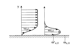
The schematic representations in Figs. 8(a) and 8(b)
illustrate this ph~nnm~non. (The minus signs ~or the
abscissas of the plots o~ ~(y) are omitted for
clarity.)
Fig. 8(a) indicates the velocity and ~z pro~iles (the
z-direction being perpendicular to the plane o~ the
paper). The velocity pro~ile shown in Fig. 8(a)
results in the depicted ~zO in accordance with
equation 7.
A velocity pro~ile like that in Fig. 8(b) results ~rom
actuation o~ the array shown in Fig. 6 as described
above. Since it is qualitatively similar to u(y) cnt in
Fig. 5, it will result in reduced drag according to
equation 4, also. And, since ~u~/~y is smaller, it
likewise results in a reduction o~ ~zO to ~'zO.
The present invention achieves even more dramatic
reductions in drag because it reduces spanwise
vorticity at the wall (~zO), while also introducing
vorticity into the ~low such that the longitudinal
vorticity induced by one control region is largely
CA 02238038 1998-0~-19
W O 97/18990 PCT~US96/18578 - 18 -
cancelled by the longit~ n;31 vorticity induced by
downstream control regions. The prior approach in U.S.
Patent 5,437,421 caused vorticity in the longitudinal
(x) direction to become concentrated in localized
regions. This limited the amount o~ drag reduction in
accordance with the ~ollowing principles.
Those skilled in the art will realize ;mme~;Ately that
actuation o~ a given control region tile does not
change the total vorticity in the ~low. While it
changes the vorticity distribution, it actually
introduces equal amounts o~ positive- and negative-
sense vorticity. Physical principles (namely,
conservation of angular mom~ntum) require that equal
amounts of negative-sense and positive-sense vorticity
be introduced in the spanwise and longitl~i n~ 1
directions because the total induced vorticity must be
zero in the ~low being controlled.
It was realized that with the previous arrangement the
positive and negative longitl~;n~l vorticity introduced
into the ~luid by a given control region was rein~orced
as the ~luid came under the in~luence o~ a later-
actuated downstream control region. In ~act, the goal
o~ that invention actually is to actuate the control
regions in a way that the vorticity introduced by one
control region is rein~orced by a subsequently-
encountered control region.
Although the invention in U.S. Patent 5,437,421
provided startling drag reductions, the present
invention proceeds ~rom the realization that the
reductions in drag achieved with that invention were
actually the result o~ reducing near-wall vorticity in
the spanwise direction (that is, ~z,O, see Fig 8) by the
redistribution o~ the velocity pro~ile in the boundary
layer. When considered ~rom the standpoint o~ the
CA 02238038 1998-0~-19
WO 97/18990 PCTAUS96/18578
- 19
vorticity distribution, it was realized that the
previous approach ~orced the flow into a regime that
rein~orced the longitll~;n~ (that is, streamwise)
vorticity ~, which is known to be a signi~icant cause
5 o~ viscous drag.
Longitudinal vorticity is known to be essential to the
existence o~ a turbulent boundary layer, and there~ore
is a major source o~ viscous drag. See Figs. 2 and 5,
along with equations 1 and 2. In a turbulent boundary
layer counter-rotating longitudinal vortices occur
somewhat regularly in the spanwise (z) direction. It
has been observed experimentally that such vortices
lead to the lift-up of near-wall ~luid, with the
subsequent replenishment of that ~luid with high-speed
~ree-stream ~luid (the so-called "burst-sweep"
phen~m~non~. The prior invention actually rein~orced
that longitudinal vorticity, thus per~orce limiting
drag reduction. The present invention enables
realization o~ even ~urther drag reductions, even
though physical principles make it impossible to avoid
introducing longitll~;n~l vorticity using the control
regions o~ the invention.
It was ~ound that an array according to Fig. 6,
actuated by a suitable control circuit in accordance
with the above description, introduces longitudinal
vorticity in a manner in which downstream control
regions tend to create longitn~;n~l vorticity
distributed such that it attenuates longitudinal
vorticity created by upstream control regions. As a
result, the drag reduction due to the decreased
spanwise vorticity ~z at the wall can be maximized.
Fig. 9 shows an alternate embodiment o~ the invention
in which the control region tiles are aligned in the x-
direction, but are actuated in a manner to provide the
CA 02238038 1998-0~-19
W O 97/1899U PCT~US96/18578
- 20 -
shaded actuated control regions, whereby the
l on git~ n;~1 vorticity concentration created by
individual tiles is counteracted by that created
downstream tiles, in accordance with the present
invention.
For an array like that shown in Fig. 9, the actuation
pattern is shown in Table 2:
Table 2
Row a Row b Row c Row d
~,-Fig,9(a)~a2-a3,alO-all,b6-b7,bl4-~15,c2-c3,clO-cll,d6-d7,dl4-dl5,
-Fi~.9(b) a3-a4,all-al2,.. b7-b8,bl5-bl6,.. c3-c4,cll-c12,.. d7-d8,dl5-d16,
~3-Fi~.9(c) a4-a5,al2-al3,.. b8-b9,bl6-bl7... c4-c5,c12-c13,.. d8-d9,dl6-dl7,
15~,,-Fig.9(d) a5-a6,al3-al4,.. bl-b2,b9-blO,... c5-c6,c13-c14,.. dl-d2,d9-dlO,
~5-Fig.9(e) a6-a7,al4-al5,.. b2-b3,blO-bll,.. c6-c7,c14-c15,.. d2-d3,dlO-dll,
~6-Fig.9~f) a7-a8,al5-al6,.. b3-b4,bll-bl2,.. c7-c8,cl5-cl6,.. d3-d4,dll-dl2,
-Fi~.9(~) a8-a9,al6-al7,.. b4-b5,bl2-bl3,.. c8-c9,c16-c17,.. d4-d5,dl2-dl3,
~8-Fig.9(h) al-a2,a9-alO,... b5-b6,bl3-bl4,.. cl-c2,c9-clO,... d5-d6,dl3-dl4,
The control region tiles, which are aligned in the x-
direction in the embodiment of Fig. 9, are actuated in
the eight-phase cycle depicted summarized in Table 2,
at a 12.5~ duty cycle ~or each phase. The frequency of
actuation is determined as discussed above.
The following working example illustrates the present
invention and veri~ies its theoretical basis as
discussed above.
Example
An array like that shown in Fig. 9 was tested in a flow
channel similar to that shown in U.S. Patent 5,437,421
(see Fig. 7). The ~lm~n~ions of the channel were
slightly modified from those discussed in the patent,
CA 02238038 1998-0~-l9
W O 97/18990 PCT~US96/18578 - 21 -
and the test section was a clo5ed circular cylinder
completely ~illed with the ~lowing fluid. A test array
was used with overall ~lmen~ions o~ about 0.22 meters
(16 control regions) in the x-direction and about 0.072
meters (7 control regions) in the z-direction. The
control regions were actuated in as discussed above in
connection with Fig. 9. The test array included
permanent magnets generating a peak transverse ~lux o~
about 0.4 gauss in the center of each tile. The tiles
were actuated by passing a peak current in an order o~
magnitude o~ about 1.0 ~a/cm2 between the pertinent
electrodes. The frequency o~ actuation was 5Hz, with a
12.5~ duty cycle, so that in 1.6 seconds all eight
phases in a given actuation sequence are actuated. The
~low velocity was about 7.50 cm/sec. The ~luid was
conductive (about 2.55 S/m), and a dye was used ~or
~low visualization as discussed in the above-mentioned
patent.
As a comparison example, equal-phase tiles were
actuated as discussed in connection with Fig. 10 in the
above-identi~ied patent.
Figs. lO(a) to lO(c) represent the results o~ the
tests. The ~low was visualized using a video recorder
facing downstream in the x-direction (as indicated by
the y-z axis at the top le~t o~ Fig. 10), with a thin
sheet of laser energy applied in the boundary layer to
cause the dye to ~luoresce. (See Fig. 7 o~ U.S. Patent
5,437,421 )
Fig. lO(a) shows the ~low conditions with the array de-
activated. The drag D on the plate having the array
was measured. The bright region B represents ~low in
the boundary layer.
CA 02238038 1998-0~-19
W O 97/18990 PCTnJS96/18578
- 22 -
Fig. lO(b) shows the ~low conditions with the array
actuated in accordance with the invention described in
the above-mentioned patent, with the total power
applied to the electrodes being 0.4 watts. The drag
was reduced by 25~ as compared to the drag without any
control regions actuated ~Fig. lO(a)), that is, oD/D =
-0.25. In addition, the regions o~ strong rotational
~low discussed in the patent (see Figs. 11 and 12) can
be clearly seen in Fig. lO(b) as regions Bl, B2, B3 o~
concentrated longitudinal vorticity that raise the
boundary layer ~low away from the surface.
Fig. lO(c) shows the ~low conditions when the array is
actuated according to the discussion above in
connection with Fig. 9. The drag has been reduced 85
as compared to the array with no control regions
actuated and 25~ as compared to the prior art as shown
in Fig. lO(b), with an applied power of only 0.02 watts
(5~ o~ that in Fig. lO(b)). Fig. lO(c) also shows that
~low in the boundary layer has been li~ted up more
uni~ormly in the spanwise (z) direction, evidencing a
decrease in ~z at the wall (see Fig. 8~b)).
The raised-up bright regions Bl, B2, B3 in Fig. lO(b)
indicate regions o~ enhanced longitudinal vorticity,
since Fig. 10 is a view looking in the longitudinal (x)
direction. Fig. lO(c) shows how the longitudinal
vorticity variations have been reduced, indicating the
results o~ reducing the concentrations o~ longitudinal
vorticity by redistributing the vorticity introduced by
the control region tiles to more uni~ormly increase
spanwise vorticity and decrease ~z at the sur~ace (see
Fig. 8(b)) along the spanwise direction Even though
the boundary layers depicted in these ~igures are
l~m; n~r, the ~igures taken together con~irm that the
present invention attenuates the lonyitudinal vorticity
concentrations introduced using the prior approach.
CA 02238038 1998-0~-19
W O 97/18990 PCTrUS96/18578
- 23 -
They also confirm the source of the variations in drag
in the spanwise direction that occur when the ~low is
controlled in accordance with the invention described
in U.S. Patent 5,437,421. Accordingly, these
experiments make it clear that the limits on drag
reduction experienced with that invention are the
result of the counter-productive influence of
rein~orcing rather than trying to cancel longitudinal
vorticity in the boundary layer.
It will be appreciated that magnetic boundary layer
control devices such as discussed above could be
provided on any surface upon which it is desired to
control the boundary layer.
The present invention provides a device that is simple
to manufacture as discrete elements and which could be
easily retrofit to craft presently in operation.
Accordingly, the magnetic boundary layer control
devices could be easily manufactured in large volume
and delivered to a site o~ operation of the craft upon
which it is to be installed. The devices could be
easily fitted on the inside skin of the craft, ~or
example on a submarine sail, with a mlnimnm amount o~
time and effort.
0~ course, it will be appreciated that the invention
may take ~orms other than those specifically described,
and the scope o~ the invention is to be determined
solely by the following claims